UM1018
User Manual
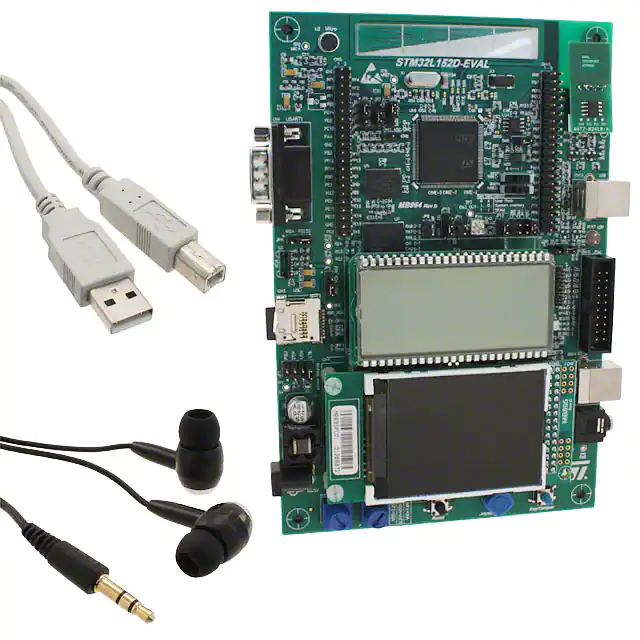
STM32L152-EVAL evaluation board
Introduction
The STM32L152-EVAL evaluation board is a complete demonstration and development
platform for STMicroelectronics’ ARM cortex-M3 core-based STM32L152VBT6
microcontroller supporting two I2C, two SPI and three USART channels, 12-bit ADC, 12-bit
DAC, 16 KB internal SRAM and 128 KB Flash, USB FS, LCD controller, touch sensing and
JTAG debugging support.
The full range of hardware features on the board helps you evaluate all peripherals (USB
FS, USART, Audio DAC, microphone ADC, dot-matrix LCD, LCD glass, IrDA, light
dependant resistor (LDR), MicroSD CardTM and temperature sensor amongst others) and
develop your own applications. Extension headers make it possible to easily connect a
daughter board or wrapping board for your specific application.
An ST-LINK/V2 is integrated on the board as embedded in-circuit debugger and
programmer for the STM32 MCU.
Figure 1.
November 2011
STM32L152-EVAL evaluation board
Doc ID 18141 Rev 2
1/10
www.st.com
�Contents
UM01018
Contents
1
2
3
2/42
Features . . . . . . . . . . . . . . . . . . . . . . . . . . . . . . . . . . . . . . . . . . . . . . . . . . . 4
1.1
Demonstration software . . . . . . . . . . . . . . . . . . . . . . . . . . . . . . . . . . . . . . . 4
1.2
Order code . . . . . . . . . . . . . . . . . . . . . . . . . . . . . . . . . . . . . . . . . . . . . . . . . 4
Hardware and layout . . . . . . . . . . . . . . . . . . . . . . . . . . . . . . . . . . . . . . . . . 5
2.1
Development and debug support . . . . . . . . . . . . . . . . . . . . . . . . . . . . . . . . 7
2.2
Power supply . . . . . . . . . . . . . . . . . . . . . . . . . . . . . . . . . . . . . . . . . . . . . . . 7
2.3
Clock source . . . . . . . . . . . . . . . . . . . . . . . . . . . . . . . . . . . . . . . . . . . . . . . . 9
2.4
Reset source . . . . . . . . . . . . . . . . . . . . . . . . . . . . . . . . . . . . . . . . . . . . . . . 9
2.5
Boot option . . . . . . . . . . . . . . . . . . . . . . . . . . . . . . . . . . . . . . . . . . . . . . . . 10
2.6
LCD glass module . . . . . . . . . . . . . . . . . . . . . . . . . . . . . . . . . . . . . . . . . . 10
2.7
Audio . . . . . . . . . . . . . . . . . . . . . . . . . . . . . . . . . . . . . . . . . . . . . . . . . . . . 11
2.8
USB . . . . . . . . . . . . . . . . . . . . . . . . . . . . . . . . . . . . . . . . . . . . . . . . . . . . . 11
2.9
RS-232 and IrDA . . . . . . . . . . . . . . . . . . . . . . . . . . . . . . . . . . . . . . . . . . . 11
2.10
Touch sensing buttons . . . . . . . . . . . . . . . . . . . . . . . . . . . . . . . . . . . . . . . 12
2.11
MicroSD Card . . . . . . . . . . . . . . . . . . . . . . . . . . . . . . . . . . . . . . . . . . . . . . 12
2.12
Analog input . . . . . . . . . . . . . . . . . . . . . . . . . . . . . . . . . . . . . . . . . . . . . . . 12
2.13
Comparator . . . . . . . . . . . . . . . . . . . . . . . . . . . . . . . . . . . . . . . . . . . . . . . 13
2.14
Temperature sensor . . . . . . . . . . . . . . . . . . . . . . . . . . . . . . . . . . . . . . . . . 14
2.15
Display and input devices . . . . . . . . . . . . . . . . . . . . . . . . . . . . . . . . . . . . . 14
2.16
IDD measurement . . . . . . . . . . . . . . . . . . . . . . . . . . . . . . . . . . . . . . . . . . 15
2.16.1
Run mode . . . . . . . . . . . . . . . . . . . . . . . . . . . . . . . . . . . . . . . . . . . . . . . 15
2.16.2
Low power mode . . . . . . . . . . . . . . . . . . . . . . . . . . . . . . . . . . . . . . . . . . 15
2.16.3
Ibias current measurement procedure . . . . . . . . . . . . . . . . . . . . . . . . . . 17
Connectors . . . . . . . . . . . . . . . . . . . . . . . . . . . . . . . . . . . . . . . . . . . . . . . 18
3.1
RS-232 connectors (CN2, CN5) . . . . . . . . . . . . . . . . . . . . . . . . . . . . . . . . 18
3.2
TFT LCD connector (CN14) . . . . . . . . . . . . . . . . . . . . . . . . . . . . . . . . . . . 18
3.3
Power connector (CN12) . . . . . . . . . . . . . . . . . . . . . . . . . . . . . . . . . . . . . 19
3.4
Daughterboard extension connectors (CN6 and CN7) . . . . . . . . . . . . . . . 19
3.5
ST-LINK/V2 programming connector CN10 . . . . . . . . . . . . . . . . . . . . . . . 22
3.6
ST-LINK/V2 USB type B connector CN11 . . . . . . . . . . . . . . . . . . . . . . . . 23
Doc ID 18141 Rev 2
�UM01018
Contents
3.7
User USB Type B connector CN1 . . . . . . . . . . . . . . . . . . . . . . . . . . . . . . 23
3.8
Audio jack CN3 . . . . . . . . . . . . . . . . . . . . . . . . . . . . . . . . . . . . . . . . . . . . . 23
3.9
JTAG connector CN9 . . . . . . . . . . . . . . . . . . . . . . . . . . . . . . . . . . . . . . . . 24
3.10
Trace debugging connector CN8 . . . . . . . . . . . . . . . . . . . . . . . . . . . . . . . 24
3.11
MicroSD Card connector CN4 . . . . . . . . . . . . . . . . . . . . . . . . . . . . . . . . . 25
3.12
BNC connector CN13 . . . . . . . . . . . . . . . . . . . . . . . . . . . . . . . . . . . . . . . . 25
4
Schematics . . . . . . . . . . . . . . . . . . . . . . . . . . . . . . . . . . . . . . . . . . . . . . . 26
5
Revision history . . . . . . . . . . . . . . . . . . . . . . . . . . . . . . . . . . . . . . . . . . . 41
Doc ID 18141 Rev 2
3/42
�Features
1
UM01018
Features
●
1.1
Four 5 V power supply options:
–
Power jack
–
ST-LINK/V2 USB connector
–
User USB connector
–
Daughterboard
●
Audio speaker and microphone connected to DAC and ADC of STM32L152VBT6
●
2 GByte or more SPI interface MicroSD CardTM
●
I2C compatible serial interface temperature sensor
●
RS-232 communication
●
IrDA transceiver
●
JTAG and trace debug support, ST-LINK/V2 embedded.
●
240x320 TFT color LCD connected to SPI interface of STM32L152VBT6
●
Joystick with 4-direction control and selector
●
Reset button
●
Tamper or Key button
●
4 color user LEDs and 3 LEDs as MCU power range indicator
●
MCU consumption measurement circuit
●
LCD glass 32 x 4 segments connected to LCD controller in STM32L152VBT6
●
Extension connector for daughterboard or wrapping board
●
MCU voltage choice of 3.3 V or adjustable from 1.65 V to 3.6 V
●
USB FS connector
●
Two touch sensing buttons
●
Light dependent resistor (LDR)
●
Potentiometer
Demonstration software
Demonstration software is preloaded in the board's Flash memory for easy demonstration of
the device peripherals in stand-alone mode. For more information and to download the
latest version available, please refer to the STM32L152-EVAL demonstration software
available on www.st.com.
1.2
Order code
To order the STM32L152VBT6 evaluation board, use the order code STM32L152-EVAL.
4/42
Doc ID 18141 Rev 2
�UM01018
2
Hardware and layout
Hardware and layout
The STM32L152-EVAL evaluation board is designed around the STM32L152VBT6
microcontroller in a 100-pin TQFP package.
Figure 1 illustrates the connections between the STM32L152VBT6 and its peripherals (color
LCD, touch sensing button, USB FS connector, temperature sensor, USART, IrDA, audio,
MicroSD Card and embedded ST-LINK/V2).
Figure 2 helps you to locate these features on the evaluation board.
Figure 1.
Hardware block diagram
*OYSTICK
,%$S
'0)/
7AKEUP
BUTTON
,$2
30 )�
-ICRO3$
#ARD
30 )�
$OT-ATRIX
,#$
6OLTAGE
TRANSLATOR
23
���
TRANSCEIVER
#OMPARATOR
53! 24���
".#
CONNECTOR
,#$'LASS
43
CONTROLL ER
!$#
34-��,���6"4�
!$#
,#$
CONTROLL ER
����6TO���6
ADJUSTABLE
REGULATOR
���6REGULATOR
3PEAKER
!MPLI FIER
53" &3
*4!'
)�#
%MBEDDED
34
,).+�6�
53" 4YPE"
CONNECTOR
*4!'�4RACE
CONNECTOR
-#5
CONSUMPTION
MEASUREMENT
%XTENSION
CONNECTORFOR
'0)/S
!
4EMPERATURE
SENSOR
0OTENTIOMETER
-ICROPHONE
!MPLI FIER
$!#
53"
CONNECTOR
53! 24�
$"�CONNECTOR
)R$!
TRANSCEIVER
&4
4OUCH
SENSING
53! 24�
$"�CONNECTOR
Doc ID 18141 Rev 2
5/42
�Hardware and layout
Figure 2.
UM01018
STM32L152-EVAL board layout
���� ��� ��������� �����
)�� ����
%��� ��������
���
��� ��
�� ������� �
����
���
!�. ��
��� !����
�#$ %��
!��
��5#�%�"�).��
�
��#
�
��� 2��/
����
+�6� 2��/
��&
'��( ��������
�
���$
��-� %��
��$
5�� ��� �� �
!�1
%�� �-���
,��
-�
����
��8%*�43)�
!�.
�
!��
* ��
��
��" !���#
%�"
��8%*�43)�
%��
���#
.�� ��������
�)�
)��7��2
��,���
6/42
$ ��-� %���
�)# +�������,���
!#1 2�0����/
.� ���� /�0
Doc ID 18141 Rev 2
.� ��,+� 34�0 �
����
�UM01018
2.1
Hardware and layout
Development and debug support
Version 2 of the ST-LINK, called ST-LINK/V2, is embedded on the board. This tool allows
on-board program loading and debugging of the STM32L using the JTAG or SWD interface.
Third-party debug tools are also supported by the JTAG (CN9) or Trace (CN8) connectors.
To communicate with the embedded ST-LINK/V2, a specific driver needs to be installed on
your PC. To download and install this driver, refer to the Software and development tools
page for the ultra low power STM32L family available on www.st.com (the install shield is
called ST-LINK_V2_USBdriver.exe).
The embedded ST-LINK/V2 connects to the PC via a standard USB cable from connector
CN11. The bicolor LED LD5 (COM) advises on the status of the communication as follows:
1.
Slow blinking Red, then Off: At power-on before USB initialization.
2.
Fast blinking Red, then Off: After the first correct communication between PC and STLink/V2 (enumeration).
3.
Red On: When initialization between PC and ST-LINK/V2 is successfully finished.
4.
Green On: After successful target communication initialization.
5.
Blinking Red/Green: During communication with target.
6.
Green On: Communication finished and OK.
7.
Orange On: Communication failure.
Note:
It is possible to power the board via CN11 (embedded ST/LINK/V2 USB connector) even if
an external tool is connected to CN8 (trace) or CN9 (external JTAG and SWD).
2.2
Power supply
The STM32L152-EVAL is designed to be powered by a 5 V DC power supply and to be
protected by PolyZen from a wrong power plug-in event. It is possible to configure the
evaluation board to use any of the following four power supply sources by setting jumpers
JP12, JP13 and JP4 (see Table 1).
●
Note:
5 V DC power adapter connected to CN12, the power jack on the board (power supply
unit (PSU on silk screen)). The external power supply is not provided with the board but
can be ordered separately.
The AC220V to DC5V power adapter PSU-5V2A (recommended, can be ordered from ST
order code PSU-5V2A) or equivalent (polarity compatible with CN12) can be used to power
the STM32L152-EVAL board via its power jack CN12.
●
5 V DC power with 500 mA limitation from CN11, the USB type B connector of STLINK/V2 (USB 5 V power source (ST-LINK/V2 on silkscreen)).
●
5 V DC power with 500 mA limitation from CN1, the USB type B connector (5 V power
source (USB on silkscreen)).
●
5 V DC power from CN6, the extension connector for daughterboard (daughterboard
power source (Daughter board on JP12 silkscreen).
Various LEDs indicate the power status:
●
Red LED LD9 is lit when the STM32L152-EVAL board is powered correctly by 5 V.
●
Red LED LD8 is lit when MCU is powered by low voltage (VDD < 1.8 V).
●
Yellow LED LD7 is lit when MCU is powered by voltage (1.8 V