STPIC6A259
POWER LOGIC 8-BIT ADDRESSABLE LATCH
PRELIMINARY DATA
■
■
■
■
■
■
■
LOW RDS(on): 1Ω TYP
OUTPUT SHORT-CIRCUIT PROTECTION
75mJ AVAILANCHE ENERGY
EIGHT 350mA DMOS OUTPUTS
50V SWITCHING CAPABILITY
FOUR DISTINCT FUNCTION MODES
LOW POWER CONSUMPTION
DESCRIPTION
This power logic 8-bit addressable latch controls
open-drain DMOS transistor outputs and is
designed
for
general-purpose
storage
applications in digital systems. Specific uses
include working registers, serial-holding registers,
and decoders or demultiplexers. This is a
multifunctional device capable of operating as
eight addressable latches or an 8-line
demultiplexer with active-low DMOS outputs.
Each open-drain DMOS transistor features an
independent chopping current-limiting circuit to
prevent damage in the case of a short circuit.
Four distinct modes of operation are selectable by
controlling the clear (CLR) and enable (G) inputs
and enumerated in the function table. In the
addressable-latch mode, data at the data-in (D)
terminal is written into the addressed latch. The
addressed DMOS-transistor output inverts the
data input with all unadressed DMOS-transistor
output remaining in their previuous state. In the
MOS-transistor outputs remain in their previous
states and are unaffected by the data or address
inputs. To eliminate the possibility of entering
erroneus data in the latch, enable G should be
)
s
(
ct
u
d
o
r
P
e
t
e
l
o
SOP
c
u
d
)
s
t(
held high (inactive) while the address lines are
changing. In the 8-line demoultiplexing mode, the
addressed output is inverted with respectto the D
input and all other output are high. In the clear
mode, all outputs are high and unaffected by the
address and data inputs.
Separate power ground (PGND) and logic ground
(LGND) terminals are providied to facilitate
maximum system flexibility. All PGND terminals
are interally connected, and each pGND terminal
must be externally connected to the power system
ground in order to minimize parasitic impedance.
A single-point connection between LGND and
PGND must be made externally in a manner that
reduces crosstalk between the logi and load
circuits.
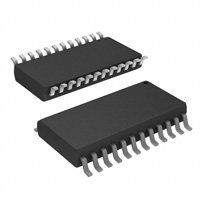
The STPIC6A259 is offered in a termally
enhanced SO-24 package. The STPIC6A259 is
characterized for operation over the operating
case temperature range -40°C to 125°C.
e
t
le
o
r
P
o
s
b
O
-
ORDERING CODES
s
b
O
Type
Package
Comments
STPIC6A259M
STPIC6A259MTR
SO-24 Batwing (Tube)
SO-24 Batwing (Tape & Reel)
50parts per tube / 20tube per box
2500 parts per reel
March 2001
1/13
This is preliminary information on a new product now in development are or undergoing evaluation. Details subject to change without notice.
�STPIC6A259
LOGIC SYMBOL AND PIN CONFIGURATION
c
u
d
FUNCTIONAL TABLE
INPUTS
CLR
G
H
L
H
L
Qio
H
L
L
H
Qio
H
H
X
Qio
Qio
L
L
L
L
L
H
H
L
X
L
H
H
H
H
H
r
P
e
o
s
b
O
-
Addressable
Latch
Memory
)
s
(
ct
u
d
o
2/13
e
t
le
SELECT INPUTS
FUNCTION
8-Line
Demultiplexer
Clear
INPUT AND OUTPUT EQUIVALENT CIRCUITS
s
b
O
o
r
P
FUNCTIONAL TABLE
OUTPUT OF EACH
ADDRESSED OTHER
D
DRAIN
DRAIN
t
e
l
o
)
s
t(
S2
L
L
L
L
H
H
H
H
DRAIN ADDRESSED
S1
S0
L
L
H
H
L
L
H
H
L
H
L
H
L
H
L
H
0
1
2
3
4
5
6
7
�STPIC6A259
ABSOLUTE MAXIMUM RATINGS
Symbol
VCC
VI
Parameter
Logic Supply Voltage (See Note 2)
Logic Input Voltage Range
Value
Unit
7
V
-0.3 to 7
V
VDS
Power DMOS Drain to Source Voltage (See Note 2)
50
V
IDS
Continuous Source to Drain Diode Anode Current
1
A
IDS
Pulsed Source to Drain Diode Anode Current (See Note 3)
2
A
ID
1.1
A
ID
Pulsed Drain Current, Each Output, All Output ON (TC=25°C)
Continuous Current, Each Output, All Output ON (TC=25°C)
350
mA
ID
Peak Drain Current Single Output (TC=25°C) (See Note 3)
1.1
A
EAS
Single Pulse Avalanche Energy (See Note 6)
75
mJ
IAS
Avalanche Current (See Note 4)
600
mA
Pd
Continuous total dissipation (TC ≤ 25°C)
1750
mW
Pd
350
mW
TJ
Continuous total dissipation (TC = 125°C)
Operating Virtual Junction Temperature Range
-40 to +150
TC
Operating Case Temperature Range
-40 to +125
Tstg
Storage Temperature Range
-65 to +150
TL
Lead Temperature 1.6mm (1/16inch) from case for 10 seconds
°C
uc
od
260
r
P
e
t
le
)
s
t(
°C
°C
°C
Absolute Maximum Ratings are those values beyond which damage to the device may occur. Functional operation under these condition is
not implied.
THERMAL DATA
Symbol
Parameter
Rthj-case
Thermal Resistance Junction-case
Rthj-amb
Thermal Resistance Junction-ambient
)
s
(
ct
RECOMMENDED OPERATING CONDITIONS
Symbol
u
d
o
o
s
b
O
-
Parameter
Unit
10
°C/W
50
°C/W
Min.
Max.
Unit
4.5
5.5
V
VCC
Logic Supply Voltage
VIH
High Level Input Voltage
0.85VCC
VCC
V
VIL
Low Level Input Voltage
0
0.15VCC
V
IDP
Pulse Drain Output Current (TC=25°C, VCC=5V) (see note 3, 5)
-1.8
0.6
tsu
Set-up Time, D High Before G ↑ (see Figure 2)
th
Hold Time, D High Before G ↑ (see Figure 2)
5
ns
Pulse Duration (see Figure 2)
15
ns
Operating Case Temperature
-40
t
e
l
o
s
b
O
tW
r
P
e
TC
10
A
ns
125
°C
3/13
�STPIC6A259
DC CHARACTERISTICS (V CC=5V, TC= 25°C, unless otherwise specified.)
Symbol
Parameter
Test Conditions
Min.
V(BR)DSX Drain-to-Source breakdown ID = 1mA
Voltage
VSD
Source-to-Drain Diode
IF = 350 mA (See Note 3)
Forward Voltage
IIH
High Level Input Current
VI = VCC
IIL
Low Level Input Current
VI = 0
ICC
Logic Supply Current
IO = 0
IOK
Output Current at Which
Chopping Starts
TC = 25°C
(See
3, 4)
VDS(on) = 0.5V
VCC = 5V
(See Note 5, 6, 7)
VDS = 40V
I(nom)
ID
Nominal Current
Off-State Drain Current
RDS(on)
Termination Resistance
(See Note 5, 6 and figg. 9,
10)
Typ.
Max.
50
V
0.8
Note 3 and Figg.
0.6
Unit
1.1
V
1
µA
-1
µA
0.5
5
mA
0.8
1.1
A
I(nom) = ID
TC=85°C
350
mA
TC=25°C
0.1
1
µA
VDS = 40V
TC=125°C
0.2
5
µA
ID = 350mA
TC=25°C
1
1.5
Ω
ID = 350mA
TC=125°C
1.7
2.5
Ω
Max.
Unit
c
u
d
o
r
P
)
s
t(
SWITCHING CHARACTERISTICS (VCC=5V, TC= 25°C, unless otherwise specified.)
Symbol
tPHL
Parameter
tr
Propagation Dealy Time,
High to Low Level Output
from D
Propagation Dealy Time,
Low to High Level Output
from D
Rise Time, Drain Output
tf
Fall Time, Drain Output
ta
Reverse Recovery Current
Rise Time
Reverse Recovery Time
tPLH
trr
Test Conditions
Min.
e
t
le
CL = 30pF
ID = 350mA
(See Figg. 1, 2, 11)
so
u
d
o
)
s
(
ct
b
O
-
IF = 350mA
di/dt = 20A/µs
(See Note 5, 6 and Fig. 5)
Typ.
30
ns
125
ns
60
ns
30
ns
100
ns
300
ns
Note 1: All Voltage valuea are with respect to LGND and PGND
Note 2: Each power DMOS source is internally connected to GND
Note 3: Pulse duration ≤ 100ms and duty cycle ≤ 2%
Note 4: Drain Supply Voltage = 15V, starting junction temperature (TJS) = 25°C. L = 210µH and IAS = 600mA (See Fig. 6)
Note 5: Technique should limit TJ - TC to 10°C maximum
Note 6: These parameters are measured with voltage sensing contacts separate from the current-carrying contacts.
Note 7: Nominal Current is defined for a consistent comparison between devices from different sources. It is the current that produces a
voltage drop of 0.5V at TC = 85°C.
r
P
e
t
e
l
o
s
b
O
4/13
�STPIC6A259
LOGIC DIAGRAM
c
u
d
e
t
le
)
s
(
ct
)
s
t(
o
r
P
o
s
b
O
-
u
d
o
r
P
e
t
e
l
o
s
b
O
5/13
�STPIC6A259
TYPICAL OPERATION MODE TEST CIRCUITS
TYPICAL OPERATION MODE WAVEFORMS
c
u
d
e
t
le
)
s
(
ct
)
s
t(
o
r
P
o
s
b
O
-
u
d
o
r
P
e
t
e
l
o
NOTE:
A) The word generator has the following characteristics: tr ≤ 10ns, tf ≤ 10ns, tW = 300ns, pulse repetition rate (PRR) = 5KHz, Z O = 50Ω
B) CL includes probe and jig capacitance.
s
b
O
6/13
�STPIC6A259
TYPICAL OPERATION MODE TEST CIRCUITS
SWITCHING TIME WAVEFORM
c
u
d
e
t
le
)
s
(
ct
)
s
t(
o
r
P
o
s
b
O
-
u
d
o
INPUT SETUP AND HOLD WAVEFORM
r
P
e
t
e
l
o
s
b
O
NOTE:
A) The word generator has the following characteristics: tr ≤ 10ns, tf ≤ 10ns, tW = 300ns, pulse repetition rate (PRR) = 5KHz, Z O = 50Ω
B) CL includes probe and jig capacitance.
7/13
�STPIC6A259
REVERSE RECOVERY CURRENT TEST CIRCUITS
c
u
d
SOURCE DRAIN DIODE WAVEFORM
e
t
le
)
s
(
ct
)
s
t(
o
r
P
o
s
b
O
-
u
d
o
r
P
e
t
e
l
o
s
b
O
NOTE:
A) The VGG amplitude and RG are adjusted for di/dt = 20A/µs. A V GG double-pulse trainn is used to set IF = 0.35A. where t 1 = 10µs, t2 = 7µs
and t3 = 3µs
B) The Drain terminal under test is connected to the TPK test point. All other terminals are connected together and connected to the TPA test
point.
C) IRM = maximum recovery current.
8/13
�STPIC6A259
SINGLE PULSE AVALANCHE ENERGY TEST CIRCUITS
SINGLE PULSE AVALANCHE ENERGY WAVEFORM
c
u
d
e
t
le
)
s
(
ct
)
s
t(
o
r
P
o
s
b
O
-
u
d
o
r
P
e
t
e
l
o
NOTE:
A) The word generator has the following characteristics: tr ≤ 10ns, tf ≤ 10ns, ZO = 50Ω
B) Input pulse duration, tW is increased until peak current IAS = 600 mA. Energy test level is defined as EAS = (IAS x V (BR)DSX x tAV )/2 = 75mJ.
s
b
O
9/13
�STPIC6A259
TYPICAL PERFORMANCE CHARACTERISTICS (unless otherwise specified Tj = 25°C)
Figure 1 : Maximum Continuous Drain Current vs
Number of Outputs Conducting Simultaneously
Figure 2 : Static Drain-Source ON-State
Resistance vs Drain Current
Figure 4 : Static Drain-Source ON-State
Resistance vs Logic Supply Voltage
c
u
d
Figure 5 : Chopping Mode Characteristics
e
t
le
)
s
(
ct
u
d
o
r
P
e
Figure 3 : MaximumPeak Drain Current vs
Number of Outputs Conducting Simultaneously
t
e
l
o
s
b
O
10/13
)
s
t(
o
r
P
o
s
b
O
-
Figure 6 : Output Current vs Case Temperature
�STPIC6A259
Figure 7 : Switching Time vs Case Temperature
Figure 8 : Switching Time vs Case Temperature
c
u
d
e
t
le
)
s
(
ct
)
s
t(
o
r
P
o
s
b
O
-
u
d
o
r
P
e
t
e
l
o
s
b
O
11/13
�STPIC6A259
SO-24 MECHANICAL DATA
mm
DIM.
MIN.
inch
TYP.
MAX.
A
MIN.
TYP.
MAX.
2.65
a1
0.10
0.104
0.20
a2
0.004
0.007
2.45
0.096
b
0.35
0.49
0.013
0.019
b1
0.23
0.32
0.009
0.012
C
0.50
0.020
c1
45 (typ.)
D
15.20
15.60
0.598
E
10.00
10.65
0.393
e
1.27
e3
13.97
)
s
t(
0.614
c
u
d
0.05
o
r
P
0.420
0.55
F
7.40
7.60
L
0.50
1.27
S
0.291
e
t
le
0.19
8 (max.)
o
s
b
O
-
0.299
0.050
r
P
e
t
e
l
o
C
e3
b1
s
E
D
24
13
1
12
F
s
b
O
e
a1
u
d
o
b
c1
A
)
s
(
ct
a2
L
P013T
12/13
�STPIC6A259
c
u
d
e
t
le
)
s
(
ct
)
s
t(
o
r
P
o
s
b
O
-
u
d
o
r
P
e
t
e
l
o
s
b
O
Information furnished is believed to be accurate and reliable. However, STMicroelectronics assumes no responsibility for the
consequences of use of such information nor for any infringement of patents or other rights of third parties which may result from
its use. No license is granted by implication or otherwise under any patent or patent rights of STMicroelectronics. Specifications
mentioned in this publication are subject to change without notice. This publication supersedes and replaces all information
previously supplied. STMicroelectronics products are not authorized for use as critical components in life support devices or
systems without express written approval of STMicroelectronics.
© The ST logo is a registered trademark of STMicroelectronics
© 2001 STMicroelectronics - Printed in Italy - All Rights Reserved
STMicroelectronics GROUP OF COMPANIES
Australia - Brazil - China - Finland - France - Germany - Hong Kong - India - Italy - Japan - Malaysia - Malta - Morocco
Singapore - Spain - Sweden - Switzerland - United Kingdom
© http://www.st.com
13/13
�
很抱歉,暂时无法提供与“STPIC6A259MTR”相匹配的价格&库存,您可以联系我们找货
免费人工找货- 国内价格 香港价格
- 1000+8.552181000+1.10326