STTH6010-Y
Automotive ultrafast recovery - high voltage diode
Datasheet - production data
Description
$
The high quality design of this diode has
produced a device with low leakage current,
regularly reproducible characteristics and intrinsic
ruggedness. These characteristics make it ideal
for heavy duty applications that demand long term
reliability like automotive applications.
.
$
These diodes also fit into auxiliary functions such
as snubber, bootstrap, and demagnetization
applications.
.
'2����
The improved performance in low leakage
current, and therefore thermal runaway guard
band, is an immediate competitive advantage for
this device.
Features
AEC-Q101 qualified
Table 1. Device summary
Ultrafast, soft recovery
IF(AV)
60 A
Very low conduction and switching losses
VRRM
1000 V
High frequency and/or high pulsed current
operation
Tj (max.)
175 °C
High reverse voltage capability
VF (typ)
1.3 V
High junction temperature
trr (typ)
49 ns
ECOPACK®2 compliant component
April 2015
This is information on a product in full production.
DocID018924 Rev 2
1/9
www.st.com
�Characteristics
1
STTH6010-Y
Characteristics
Table 2. Absolute ratings (limiting values at 25 °C, unless otherwise specified)
Symbol
Parameter
VRRM
Repetitive peak reverse voltage
IF(RMS)
Forward rms current
Value
Unit
1000
V
80
A
IF(AV)
Average forward current
Tc = 75 °C, = 0.5, square wave
60
A
IFRM
Repetitive peak forward current
tp = 5 µs, F = 5 kHz square
450
A
IFSM
Surge non repetitive forward current
tp = 10 ms sinusoidal
400
A
Tstg
Storage temperature range
-65 to + 175
°C
Operating junction temperature range
-40 to + 175
°C
Value
Unit
0.78
°C/W
Tj
Table 3. Thermal parameters
Symbol
Rth(j-c)
Parameter
Junction to case
Table 4. Static electrical characteristics
Symbol
IR(1)
Parameter
Reverse leakage current
Test conditions
Tj = 25 °C
Tj = 125 °C
Forward voltage drop
Tj = 100 °C
IF = 60 A
1. Pulse test: tp = 5 ms, < 2%
2. Pulse test: tp = 380 µs, < 2%
To evaluate the conduction losses use the following equation:
P = 1.3 x IF(AV) + 0.0067 IF2(RMS)
DocID018924 Rev 2
Unit
20
µA
-
20
-
Tj = 150 °C
2/9
Typ. Max.
VR = VRRM
Tj = 25 °C
VF(2)
Min.
200
2.0
-
1.4
1.8
-
1.3
1.7
V
�STTH6010-Y
Characteristics
Table 5. Dynamic characteristics
Symbol
Parameter
Test conditions
Min.
Typ.
Max.
Unit
IF = 1 A, dlF/dt = -50 A/µs,
VR = 30 V, Tj = 25 °C
-
IF = 1 A, dlF/dt = -100 A/µs,
VR = 30 V, Tj = 25 °C
-
61
80
IF = 1 A, dlF/dt = -200 A/µs,
VR = 30 V, Tj = 25 °C
-
49
65
Reverse recovery current
IF = 60 A, dlF/dt = -200 A/µs,
VR = 600 V, Tj = 125 °C
-
31
40
A
S
Softness factor
IF = 60 A, dlF/dt = -200 A/µs,
VR = 600 V, Tj = 125 °C
-
1
tfr
Forward recovery time
IF = 60 A, dlF/dt = 100 A/µs,
VFR = 1.5 x VFmax, Tj = 25 °C
-
750
ns
Forward recovery voltage
IF = 60 A, dlF/dt = 100 A/µs,
Tj = 25 °C
-
Reverse recovery time
trr
IRM
VFP
Figure 1. Conduction losses versus average
current
115
4
ns
V
Figure 2. Forward voltage drop versus forward
current
,)0�$�
���
3�:�
���
���
�
���
���
���
7M� �����&
�0D[LPXP�YDOXHV�
���
���
���
���
����
7M� �����&
���
��
�7\SLFDO�YDOXHV�
���
7M� ����&
�0D[LPXP�YDOXHV�
��
��
��
��
7
��
��
,)�$9�� $�
��
�
�
��
��
��
��
��
��
��
��
9)0�9�
�
���
DocID018924 Rev 2
���
���
���
���
���
���������������������
3/9
9
�Characteristics
STTH6010-Y
Figure 3. Relative variation of thermal
impedance junction to case versus pulse
duration
Figure 4. Peak reverse recovery current versus
dlF/dt (typical values)
=WK�M�F��5WK�M�F�
,50�$�
���
��
6LQJOH�SXOVH
���
9 � �����9
5
7M� �����&
��
���
, ���[�,
)�
)�$9�
, � �,
) )�$9�
��
���
���
��
,
)�
���
�����[�,
)�$9�
��
���
���
��
���
��
���
W S �V�
��(���
��(���
GO)�GW�$�V�
�
���
��(���
�
��(���
Figure 5. Reverse recovery time versus dlF/dt
(typical values)
��
���
���
���
���
���
���
���
���
���
Figure 6. Reverse recovery charges versus
dlF/dt (typical values)
W UU �QV�
4UU�&�
���
��
95� �����9
7M� �����&
���
,)� ���[�,)�$9�
�
, � ���[�,
)
)�$9�
���
95� �����9
7M� �����&
�
�
,)� ��,)�$9�
�
���
, � ��,
)
)�$9�
�
���
�
,)� �����[�,)�$9�
�
���
�
���
, � �����[�,
)
)�$9�
�
GO)�GW�$�V�
�
GO)�GW�$�V�
�
�
��
���
���
���
���
���
���
���
���
���
�
Figure 7. Softness factor versus
dlF/dt (typical values)
��
���
���
���
���
���
���
���
���
���
Figure 8. Relative variations of dynamic
parameters versus junction temperature
6�IDFWRU
����
���
,)� ���[�,)�$9�
95� �����9
7M� �����&
���
����
,)� �,)�$9�
95� �����9
5HIHUHQFH���7M� �����&
6IDFWRU
���
���
���
���
����
���
,50
���
����
���
W55
455
���
GO)�GW�$�V�
����
�
4/9
��
���
���
���
���
���
���
7M�&�
���
���
���
���
��
DocID018924 Rev 2
��
��
���
���
�STTH6010-Y
Characteristics
Figure 9. Transient peak forward voltage
versus dlF/dt (typical values)
Figure 10. Forward recovery times versus dlF/dt
(typical values)
WIU�QV�
9)3�9�
����
��
,)� �,)�$9�
9)5� �����[�9)�PD[�
,)� �,)�$9�
7M� �����&
��
7M� �����&
����
��
��
���
��
��
���
�
�
���
�
�
GO)�GW�$�V�
GO)�GW�$�V�
�
�
���
���
���
���
���
���
Figure 11. Junction capacitance versus reverse
voltage applied (typical values)
�
���
���
���
���
���
Figure 12. Threshold voltage versus junction
temperature
&�S)�
9W��9�
����
����
)� ���0+]
926&� ����P9506
7M� ����&
����
����
0D[LPXP�YDOXHV
����
����
���
����
����
7\SLFDO�YDOXHV
����
����
95�9�
�
� �
7M�&�
����
��
���
����
��
��
��
���
���
���
Figure 13. Dynamic resistance versus junction
temperature
���
5G�Pȍ�
���
���
0D[LPXP�YDOXHV
���
���
���
���
���
���
���
7\SLFDO�YDOXHV
���
���
7M�&�
���
��
��
��
���
���
���
DocID018924 Rev 2
5/9
9
�Package information
2
STTH6010-Y
Package information
Epoxy meets UL94, V0
Cooling method: by conduction (C)
Recommended torque value: 0.80 N·m
Maximum torque value: 1.0 N·m
In order to meet environmental requirements, ST offers these devices in different grades of
ECOPACK® packages, depending on their level of environmental compliance. ECOPACK®
specifications, grade definitions and product status are available at: www.st.com.
ECOPACK® is an ST trademark.
2.1
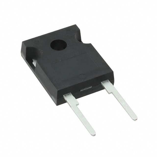
DO-247 package information
Figure 14. DO-247 package outline
9
'LD
9
$
+
/�
/
/�
)�
/�
/�
/�
)�
'
9�
)
*
6/9
DocID018924 Rev 2
0
(
�STTH6010-Y
Package information
Table 6. DO-247 package mechanical data
Dimensions
Ref.
Inches(1)
Millimeters
Typ.
Min.
Max.
A
4.85
D
Min.
Max.
5.15
0.191
0.203
2.20
2.60
0.086
0.102
E
0.40
0.80
0.015
0.031
F
1.00
1.40
0.039
0.055
0.078
0.094
F2
2.00
F3
G
Typ.
0.078
2.00
2.40
10.90
0.429
H
15.45
15.75
0.608
0.620
L
19.85
20.15
0.781
0.793
L1
3.70
4.30
0.145
0.169
0.559
0.582
0.078
0.118
0.139
0.143
L2
18.50
L3
0.728
14.20
14.80
L4
34.60
1.362
L5
5.50
0.216
M
2.00
3.00
V
5°
5°
V2
60°
60°
Dia.
3.55
3.65
1. Values in inches are converted from mm and rounded to 4 decimal digits.
DocID018924 Rev 2
7/9
9
�Ordering information
3
STTH6010-Y
Ordering information
Table 7. Ordering information
4
Order code
Marking
Package
Weight
Base qty.
Delivery mode
STTH6010WY
STTH6010WY
DO-247
4.4 g
30
Tube
Revision history
Table 8. Document revision history
8/9
Date
Revision
Changes
04-Nov-2011
1
Initial release.
22-Apr-2015
2
Added Figure 12 and Figure 13.
Document updated to current standard.
DocID018924 Rev 2
�STTH6010-Y
IMPORTANT NOTICE – PLEASE READ CAREFULLY
STMicroelectronics NV and its subsidiaries (“ST”) reserve the right to make changes, corrections, enhancements, modifications, and
improvements to ST products and/or to this document at any time without notice. Purchasers should obtain the latest relevant information on
ST products before placing orders. ST products are sold pursuant to ST’s terms and conditions of sale in place at the time of order
acknowledgement.
Purchasers are solely responsible for the choice, selection, and use of ST products and ST assumes no liability for application assistance or
the design of Purchasers’ products.
No license, express or implied, to any intellectual property right is granted by ST herein.
Resale of ST products with provisions different from the information set forth herein shall void any warranty granted by ST for such product.
ST and the ST logo are trademarks of ST. All other product or service names are the property of their respective owners.
Information in this document supersedes and replaces information previously supplied in any prior versions of this document.
© 2015 STMicroelectronics – All rights reserved
DocID018924 Rev 2
9/9
9
�