T1620T-8I, T1635T-8I
Snubberless™ 16 A Triac
Datasheet − production data
Features
A2
■
High static and dynamic commutation
■
Three quadrants
■
Snubberless device
■
Package is RoHS (2002/95/EC) compliant
■
Tab insulated, voltage = 2500 V rms
■
UL certified (ref. file E81734)
G
A1
A1
A2
G
Applications
■
General purpose AC line load switching
■
Home appliances:
– Fan
– Pump
– Solenoid
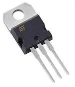
TO-220AB insulated
(T1620T-8l
T1635T-8l)
Table 1.
Device summary
Order code
Quadrants
Value IGT (mA)
■
Lighting
T1620T-8I
I - II - III
20
■
Heaters
T1635T-8I
I - II - III
35
■
Inrush current limiting circuits
■
Overvoltage crowbar protection circuits
Description
Available in TO220AB-Ins. (ceramic insulated),
the T1620T-8I, and T1635T-8I Triacs can be used
as on/off or phase angle function controllers in
general purpose AC switching.
These devices can be used without snubber (R +
C networks) if the datasheet limits are respected.
Provides insulation rated at 2500 V rms (TO220AB insulated package).
TM: Snubberless is a trademark of STMicroelectronics
April 2012
This is information on a product in full production.
Doc ID 022134 Rev 2
1/10
www.st.com
10
�Characteristics
T1620T-8I, T1635T-8I
1
Characteristics
Table 2.
Absolute maximum rating (Tj = 25 °C, unless otherwise specified)
Symbol
IT(RMS)
ITSM
I²t
Parameter
16
Tc = 119 °C
12
F = 50 Hz
tp = 20 ms
120
F = 60 Hz
tp = 16.7 ms
126
tp = 10 ms
95
Tj = 150 °C
600
Tj = 125 °C
800
Tj = 25 °C
900
V
F = 100 Hz
100
A/µs
Tj = 150 °C
4
A
Tj = 150 °C
1
W
-40 to +150
-40 to +150
°C
Lead temperature for soldering during 10 s
(at 4 mm from case for TO220AB-ins.)
260
°C
Insulation rms voltage, 1 minute, TO220AB ceramic insulated
2500
V
Non repetitive surge peak on-state current (full
cycle, Tj initial = 25 °C)
I²t Value for fusing
Repetitive peak off-state voltage, gate open
VDSM,
VRSM
Non repetitive surge peak off-state voltage
dI/dt
Critical rate of rise of on-state current IG = 2 x IGT
IGM
Peak gate current
Tstg
Tj
TL
Vins
(rms)
2/10
Unit
Tc = 108 °C
On-state rms current (full sine wave)
VDRM/
VRRM
PG(AV)
Value
tp = 10 ms
tp = 20 µs
Average gate power dissipation
Storage junction temperature range
Operating junction temperature range
Doc ID 022134 Rev 2
A
A
A²s
V
�T1620T-8I, T1635T-8I
Table 3.
Characteristics
Electrical characteristics (Tj = 25 °C, unless otherwise specified)
Value
Symbol
Test conditions
Quadrant
Unit
T1620T T1635T
I - II - III
MIN.
1
1.75
mA
I - II - III
MAX.
20
35
mA
VD = 12 V, RL = 30 Ω
All
MAX.
1.3
V
VD = 800 V, RL = 3.3 kΩ, Tj = 125 °C
All
MIN.
0.2
V
IGT (1)
VD = 12 V, RL = 30 Ω
VGT
VGD
(1)
IH
IT = 500 mA
MAX.
25
45
35
55
40
65
1000
2000
500
1000
6
16
4.5
12
I - III
IL
dV/dt (1)
IG = 1.2 IGT
MAX.
mA
II
VD = 67% x 800 V gate open
Tj = 125 °C
VD = 67% x 600 V gate open
Tj = 150 °C
(dl/dt)c (1) (dV/dt)c = snubberless (> 20 V/µs)
MIN.
Tj = 125 °C
V/µs
MIN.
Tj = 150 °C
tGT
gate controlled turn on time ITM = 13 A, VD = 400 V,
IG = 100 mA, dIG/dt = 100 mA/µs, RL = 30 Ω
I - II - III
mA
TYP.
A/ms
2
µs
1. For both polarities of A2 referenced to A1
Table 4.
Static characteristics
Symbol
VTM
(1)
Vto (1)
Rd
(1)
IDRM
IRRM
Test conditions
Value
Unit
ITM = 22.6 A, tp = 380 µs
Tj = 25 °C
MAX.
1.55
V
Threshold voltage
Tj = 150 °C
MAX.
0.85
V
Dynamic resistance
Tj = 150 °C
MAX.
30
mΩ
5
µA
Tj = 25 °C
VDRM = VRRM = 800 V
Tj = 125 °C
VDRM = VRRM = 600 V
Tj = 150 °C
MAX.
1
mA
3.6
1. for both polarities of A2 referenced to A1
Table 5.
Thermal resistance
Symbol
Parameter
Value
Unit
Rth(j-c)
Junction to case (AC)
2.1
°C/W
Rth(j-a)
Junction to ambient
60
°C/W
Doc ID 022134 Rev 2
3/10
�Characteristics
Figure 1.
20
T1620T-8I, T1635T-8I
Maximum power dissipation versus Figure 2.
on-state rms current (full cycle)
P(W)
18
180°
18
On-state rms current versus case
temperature (full cycle)
IT(RMS)(A)
16
16
14
14
12
12
10
10
8
8
6
6
4
4
2
2
IT(RMS)(A)
0
0
2
4
Figure 3.
3.0
6
8
10
12
14
On-state rms current versus
ambient temperature (free air
convection)
IT(RMS)(A)
16
TC(°C)
0
0
25
Figure 4.
1.0E+00
50
75
100
125
150
Relative variation of thermal
impedance versus pulse duration
K = [Zth / Rth]
Zth(j-c)
2.5
Zth(j-a)
2.0
1.5
1.0E-01
1.0
0.5
Ta(°C)
0.0
0
25
Figure 5.
50
Tp(s)
75
100
125
150
1.0E-02
1.0E-03 1.0E-02 1.0E-01 1.0E+00 1.0E+01 1.0E+02 1.0E+03 1.0E+04
On-state characteristics (maximum Figure 6.
values)
1000
ITM(A)
130
Tjmax:
Vto = 0.85 V
Rd = 30 mΩ
Surge peak on-state current versus
number of cycles
ITSM(A)
120
110
t = 20 ms
100
90
100
One cycle
80
Non repetitive
Tj initial = 25 °C
70
60
Tj = 150 °C
50
10
Repetitive
Tc = 108 °C
40
30
Tj = 25 °C
20
0
4/10
10
VTM(V)
1
1
2
3
4
Number of cycles
0
5
Doc ID 022134 Rev 2
1
10
100
1000
�T1620T-8I, T1635T-8I
Figure 7.
10000
Characteristics
Non repetitive surge peak on-state Figure 8.
current and corresponding values
of I2t
ITSM (A), I²t (A²s)
2.0
Relative variation of gate trigger
current versus junction
temperature
IGT[Tj]/IGT[Tj = 25 °C]
Tj initial = 25 °C
typical values
3Q IGT Q3
1.5
1000
ITSM
3Q IGT Q1-Q2
1.0
dl /dt limitation: 100 A / µs
I²t
100
0.5
tp(ms)
sinusoidal pulse with width tp
很抱歉,暂时无法提供与“T1635T-8I”相匹配的价格&库存,您可以联系我们找货
免费人工找货- 国内价格 香港价格
- 50+4.0092250+0.49875
- 200+3.91377200+0.48688
- 1000+3.818311000+0.47500
- 2000+3.722852000+0.46313
- 6250+3.627396250+0.45125
- 国内价格 香港价格
- 50+3.6751250+0.45719
- 250+3.57967250+0.44532
- 1000+3.484211000+0.43344
- 2500+3.436482500+0.42750
- 6250+3.341026250+0.41563
- 国内价格
- 1+11.27960
- 10+6.72870
- 20+4.71010
- 50+3.36440
- 100+3.19620
- 500+2.96070


 工商网监
湘ICP备2023018690号
工商网监
湘ICP备2023018690号
