TS4041
1.225V MICROPOWER SHUNT VOLTAGE REFERENCE
s 1.225V TYP OUTPUT VOLTAGE s ULTRA LOW OPERATING CURRENT : 65µA
maximum at 25°C
s HIGH PRECISION @ 25°C
+/- 2% +/- 1% +/- 0.5% s HIGH STABILITY WHEN USED WITH CAPACITIVE LOADS s INDUSTRIAL TEMPERATURE RANGE: -40 to +85°C s 150ppm/°C MAXIMUM TEMPERATURE COEFFICIENT DESCRIPTION The TS4041 is a low power shunt voltage reference providing a stable 1.225V output voltage over the industrial temperature range (-40 to +85°C). Availabe in SOT23-3 surface mount package, it can be designed in applications where space saving is a critical issue. The low operating current is a key advantage for power restricted designs. In addition, the TS4041 is very stable and can be used in a broad range of application conditions. APPLICATION
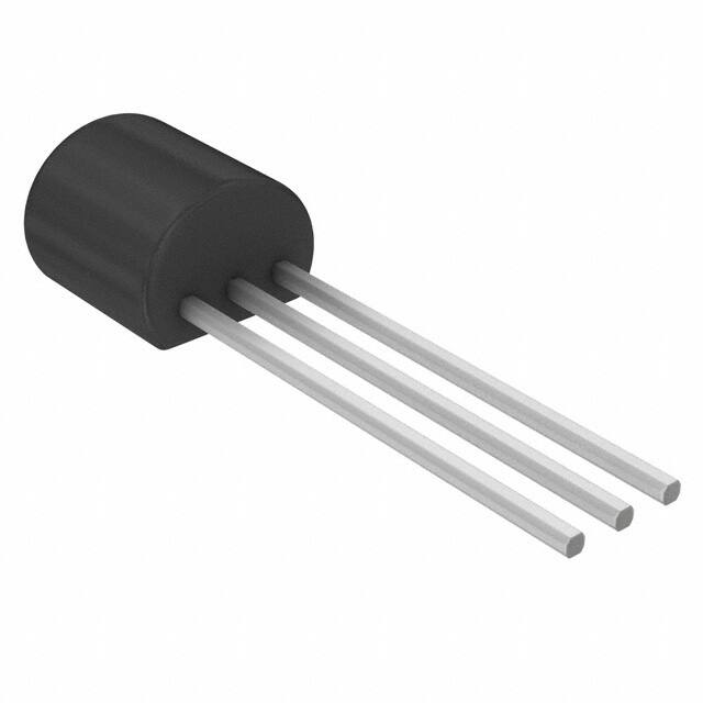
Z TO92 (Plastic Package)
L SOT23-3L (Plastic Micropackage)
PIN CONNECTIONS (top view)
s s s s s
Computers Instrumentation Battery chargers Switch Mode Power Supply Battery operated equipments
ORDER CODE
Precision TO92 SOT23-3 SOT23 Marking L233 L232 L231
2% TS4041EIZ-1.2 TS4041EILT-1.2 1% TS4041DIZ-1.2 TS4041DILT-1.2 0.5% TS4041CIZ-1.2 TS4041CILT-1.2 Single temperature range: -40 to +85°C
Z = T O92 Plastic package - also available in Bulk (Z), Tape & Reel (ZT) and Ammo Pack (AP) L T = Tiny Package (SOT23-3) - only available in Tape & Reel (LT)
March 2002
1/9
�TS4041
ABSOLUTE MAXIMUM RATINGS
Symbol Ik If Pd Tstd ESD Tlead Parameter Reverse Breakdown Current Forward Current Power Dissipation
1)
Value 20 10 360 625 -65 to +150 2 200 260
Unit mA mA mW °C kV V °C
SOT23-3 TO92
Storage Temperature Human Body Model (HBM) Machine Model (MM) Lead Temperature (soldering, 10 seconds)
1. Pd has been calculated with T amb = 25°C and Tj = 150°C and Rthja = 200°C/W for the TO92 package Rthja = 340°C/W for the SOT23-3L package
OPERATING CONDITIONS
Symbol Imin Imax Toper Minimum Operating Current Maximum Operating Current Operating Free Air Temperature Range Parameter Value 65 12 -40 to +85 Unit µA mA °C
ELECTRICAL CHARACTERISTICS TS4041E (2% Precision) Tamb = 25°C (unless otherwise specified)
Symbol Vk Parameter Reverse Breakdown Voltage Test Condition Ik = 100µA Min. 1.200 -25 -36 40 Typ. 1.225 Max. 1.250 +25 +36 65 70 150 0.3 2.5 0.25 120 200 2 2.5 8 10 0.5 Unit V mV µA ppm/°C
I = 100µA Reverse Breakdown Voltage Tolerance k -40°C < Tamb < +85°C Minimum Operating Current Tamb = 25°C -40°C < Tamb < +85°C Ik = 100µA Ikmin < Ik < 1mA -40°C < Tamb < +85°C 1mA < Ik < 12mA -40°C < Tamb < +85°C ∆Ik = 45µA to 1mA Ik = 100µA, t = 1000hrs Ik = 100µA 10Hz < f < 10kHz
Ikmin
∆Vref/∆T Average Temperature Coefficient ∆Vk/∆Ik Reverse Breakdown Voltage Change with Operating Current Range Static Impedance Long Term Stability Wide Band Noise
mV Ω ppm nV/√Hz
Rka Kvh En
Note : Limits are 100% production tested at 25°C. Limits over temperature are guaranteed through correlation and by design.
2/9
�TS4041
ELECTRICAL CHARACTERISTICS TS4041D (1% Precision) Tamb = 25°C (unless otherwise specified)
Symbol Vk Parameter Reverse Breakdown Voltage Test Condition Ik = 100µA Min. 1.213 -12 -25 40 Typ. 1.225 Max. 1.237 +12 +25 65 70 150 0.3 2.5 0.25 120 200 2 2.5 8 10 0.5 Unit V mV µA ppm/°C
I = 100µA Reverse Breakdown Voltage Tolerange k -40°C < Tamb < +85°C Minimum Operating Current Tamb = 25°C -40°C < Tamb < +85°C Ik = 100µA Ikmin < Ik < 1mA -40°C < Tamb < +85°C 1mA < Ik < 12mA -40°C < Tamb < +85°C ∆Ik = 45µA to 1mA Ik = 100µA, t = 1000hrs Ik = 100µA 10Hz < f < 10kHz
Ikmin
∆Vref/∆T Average Temperature Coefficient ∆Vk/∆Ik Reverse Breakdown Voltage Change with Operating Current Range Static Impedance Long Term Stability Wide Band Noise
mV Ω ppm nV/√Hz
Rka Kvh En
Note : Limits are 100% production tested at 25°C. Limits over temperature are guaranteed through correlation and by design.
ELECTRICAL CHARACTERISTICS TS4041C (0.5% Precision)Tamb = 25°C (unless otherwise specified)
Symbol Vk Parameter Reverse Breakdown Voltage Test Condition Ik = 100µA Min. 1.219 -6 -16 40 Typ. 1.225 Max. 1.231 +6 +16 60 65 120 0.3 2.5 0.25 120 200 1.5 2 6 8 0.5 Unit V mV µA ppm/°C
I = 100µA Reverse Breakdown Voltage Tolerange k -40°C < Tamb < +85°C Minimum Operating Current Tamb = 25°C -40°C < Tamb < +85°C Ik = 100µA Ikmin < Ik < 1mA -40°C < Tamb < +85°C 1mA < Ik < 12mA -40°C < Tamb < +85°C ∆Ik = 45µA to 1mA Ik = 100µA, t = 1000hrs Ik = 100µA 10Hz < f < 10kHz
Ikmin
∆Vref/∆T Average Temperature Coefficient ∆Vk/∆Ik Reverse Breakdown Voltage Change with Operating Current Range Static Impedance Long Term Stability Wide Band Noise
mV Ω ppm nV/√Hz
Rka Kvh En
Note : Limits are 100% production tested at 25°C. Limits over temperature are guaranteed through correlation and by design.
3/9
�TS4041
Reference voltage versus cathode current
12 8 4 0 -4 -8
Reference voltage versus cathode current
100 Cathode current (µA)
Cathode current (mA)
50
0
-50
-1 -0.5 0 0.5 1 1.5
-1
-0.5
Reference voltage (V)
0 1 0.5 Reference voltage (V)
1.5
Test circuit
Reference voltage versus Temperature
1.26 1.25 Cathode voltage (V)
R Ik=(Vin-Vref)/R Vout=Vref
+2% +1% +0.5%
1.24 1.23 1.22 1.21 1.2 1.19 -40
-0.5% -1% -2%
-20 0 20 40 60 80 Temperature (°C)
Static impedance versus temperature
0.25 Static impedance (Ohms) 0.24 0.23 0.22 0.21 0.2 -40
Noise voltage versus frequency
800
CL=10µF Noise voltage (nV/Hz)
600
400
CL=100µF
200
CL=0µF
0
-20
0 20 40 60 Temperature (°C)
80
0
1
10
100
1,000
10,000
Frequency (kHz)
4/9
�TS4041
Pulse response for Ik=100µA
3V
Test circuit for pulse response at Ik=100µA
18K Ω
Ik=1 00µA
0V Input
1.225V 0V Output
0
2
4
6
8
10
Time (µs)
Pulse response for Ik=1mA
3V Input
Test circuit for pulse response at Ik=1mA
1.8K Ω
Ik=1m A
0V
1.225V Output 0V
0
2
4
6
8
10
Time (µs)
Output
5/9
Intput
Pulse G enerator
Output
Intput
P ulse G enerator
�TS4041
PACKAGE MECHANICAL DATA 3 PINS - PLASTIC PACKAGE TO92 (TAPE & REEL)
A1 P P T H
d
A
H1
H0
H
I1
W0
D0 F1 F2 P2 P0
W2 W1 W
L1
Millimeters Dim. Min AL A T d I1 P PO P2 F1/F2 ∆h ∆P W W0 W1 W2 H H0 H1 DO L1 Typ. Max. 5.0 5.0 4.0 0.45 2.5 11.7 12.4 5.95 2.4 -1 -1 17.5 5.7 8.5 12.7 12.7 6.35 2.5 0 0 18.0 6 9 13.7 13 6.75 2.8 1 1 19.0 6.3 9.75 0.5 20 16.5 25 4.2 11 0.098 0.461 0.488 0.234 0.094 -0.039 -0.039 0.689 0.224 0.335 Min.
Inches Typ. Max. 0.197 0.197 0.157 0.018 0.500 0.500 0.250 0.098 0 0 0.709 0.236 0.354 0.539 0.512 0.266 0.110 0.039 0.039 0.748 0.248 0.384 0.020 0.787 0.650 0.984 0.165 0.433
15.5 3.8
16 4.0
0.610 0.150
0.630 0.157
6/9
�TS4041
PACKAGE MECHANICAL DATA 3 PINS - PLASTIC PACKAGE TO92 (TAPE AMMO PACK)
A1 P P T H
d
A
H1
H0
H
I1
W0
D0 F1 F2 P2 P0
W2 W1 W
L1
Millimeters Dim. Min AL A T d I1 P PO P2 F1/F2 ∆h ∆P W W0 W1 W2 H H0 H1 DO L1 Typ. Max. 5.0 5.0 4.0 0.45 2.5 11.7 12.4 5.95 2.4 -1 -1 17.5 5.7 8.5 12.7 12.7 6.35 2.5 0 0 18.0 6 9 13.7 13 6.75 2.8 1 1 19.0 6.3 9.75 0.5 20 16.5 25 4.2 11 0.098 0.461 0.488 0.234 0.094 -0.039 -0.039 0.689 0.224 0.335 Min.
Inches Typ. Max. 0.197 0.197 0.157 0.018 0.500 0.500 0.250 0.098 0 0 0.709 0.236 0.354 0.539 0.512 0.266 0.110 0.039 0.039 0.748 0.248 0.384 0.020 0.787 0.650 0.984 0.165 0.433
15.5 3.8
16 4.0
0.610 0.150
0.630 0.157
7/9
�TS4041
PACKAGE MECHANICAL DATA 3 PINS - PLASTIC PACKAGE TO92 (BULK)
Millimeters Dim. Min L B O1 C K O2 a 3.2 4.45 4.58 12.7 0.407 0.35 Typ. 1.27 3.7 5.00 5.03 0.5 Max. 4.2 5.2 5.33 0.508 Min. 0.126 0.1752 0.1803 0.5 0.016 0.0138
Inches Typ. 0.05 0.1457 0.1969 0.198 0.0197 Max. 0.1654 0.2047 0.2098 0.02
8/9
�TS4041
PACKAGE MECHANICAL DATA 3 PINS - TINY PACKAGE (SOT23)
D
e
GAUGE PLANE 0.25
k
L E1 E b
c
e1
C
A2
Millimeters Dimensions Min. A A1 A2 b c D E E1 e e1 L L1 k 0.890 0.010 0.880 0.300 0.080 2.800 2.100 1.200 Typ. Max. 1.120 0.100 1.020 0.500 0.200 3.040 2.640 1.400 Min. 0.035 0.0004
A1
A
0.10
SEATING PLANE
C
L1
Inches Typ. Max. 0.044 0.004 0.040 0.020 0.008 0.120 0.104 0.055
0.950
0.037 0.012 0.003 0.110 0.083 0.047
2.900 1.300 0.950 1.900 0.500 0.540
0.114 0.051 0.037 0.075 0.020 0.021
0.400 0°
0.600 8°
0.016
0.024
Information furnished is believed to be accurate and reliable. However, STMicroelectronics assumes no responsibility for the consequences of use of such information nor for any infringement of patents or other rights of third parties which may result from its use. No license is granted by implication or otherwise under any patent or patent rights of STMicroelectronics. Specifications mentioned in this publication are subject to change without notice. This publication supersedes and replaces all information previously supplied. STMicroelectronics products are not authorized for use as critical components in life support devices or systems without express written approval of STMicroelectronics. © The ST logo is a registered trademark of STMicroelectronics © 2002 STMicroelectronics - Printed in Italy - All Rights Reserved STMicroelectronics GROUP OF COMPANIES Australia - Brazil - Canada - China - Finland - France - Germany - Hong Kong - India - Israel - Italy - Japan - Malaysia Malta - Morocco - Singapore - Spain - Sweden - Switzerland - United Kingdom - United States © http://www.st.com - United Kingdom
9/9
�
很抱歉,暂时无法提供与“TS4041DIZ-1.2”相匹配的价格&库存,您可以联系我们找货
免费人工找货