TS881
Rail-to-rail 0.9 V nanopower comparator
Datasheet - production data
Description
The TS881 device is a single comparator
featuring ultra low supply current (210 nA typical
with output high, VCC = 1.2 V, no load) with rail-torail input and output capability. The performance
of this comparator allows it to be used in a wide
range of portable applications. The TS881 device
minimizes battery supply leakage and therefore
enhances battery lifetime.
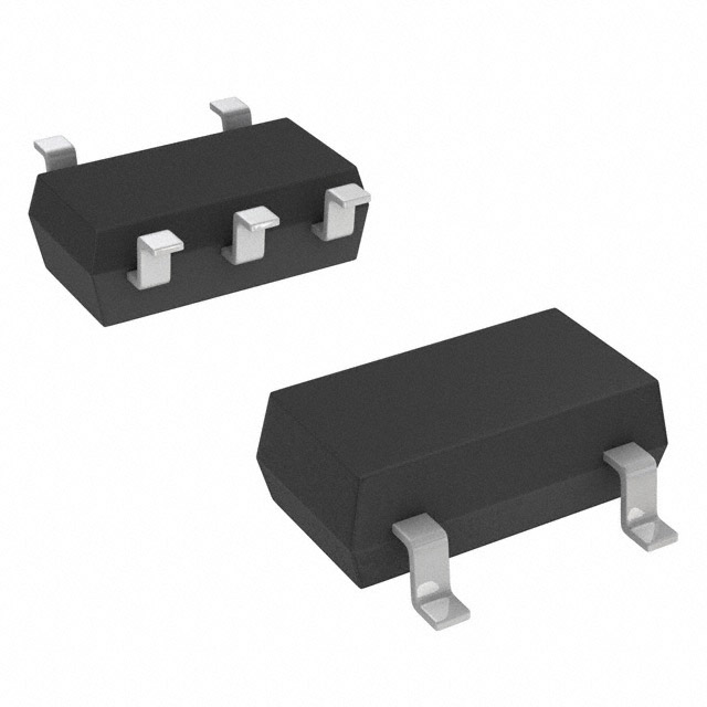
SC70-5 (top view)
Operating from 0.85 V to 5.5 V supply voltage,
this comparator can be used over a wide
temperature range (-40 to +125 °C) keeping the
current consumption at an ultra low level.
The TS881 device is available in the SC70-5 and
the SOT23-5 package, allowing great space
saving on the PCB.
SOT23-5 (top view)
Figure 1. Pin connections (top view)
Features
�
287
Ultra low current consumption: 210 nA typ.
�
9&&�
Propagation delay: 2 µs typ.
9&&�
Rail-to-rail inputs
�
��
Push-pull output
Supply operation from 0.85 V to 5.5 V
,1�
�
�
Wide temperature range: -40 to +125 °C
ESD tolerance: 8 kV HBM / 300 V MM
,1�
SC70-5
SMD package
Applications
�
287
�
9&& �
�
,1�
�
�
9&&�
�
,1�
Portable systems
Signal conditioning
Medical
SOT23-5
December 2013
This is information on a product in full production.
DocID023340 Rev 2
1/21
www.st.com
�Contents
TS881
Contents
1
Absolute maximum ratings and operating conditions . . . . . . . . . . . . . 5
2
Electrical characteristics . . . . . . . . . . . . . . . . . . . . . . . . . . . . . . . . . . . . . 6
3
Package information . . . . . . . . . . . . . . . . . . . . . . . . . . . . . . . . . . . . . . . . 17
4
Ordering information . . . . . . . . . . . . . . . . . . . . . . . . . . . . . . . . . . . . . . . 20
5
Revision history . . . . . . . . . . . . . . . . . . . . . . . . . . . . . . . . . . . . . . . . . . . 20
2/21
DocID023340 Rev 2
�TS881
List of figures
List of figures
Figure 1.
Figure 2.
Figure 3.
Figure 4.
Figure 5.
Figure 6.
Figure 7.
Figure 8.
Figure 9.
Figure 10.
Figure 11.
Figure 12.
Figure 13.
Figure 14.
Figure 15.
Figure 16.
Figure 17.
Figure 18.
Figure 19.
Figure 20.
Figure 21.
Figure 22.
Figure 23.
Figure 24.
Figure 25.
Figure 26.
Figure 27.
Figure 28.
Figure 29.
Figure 30.
Figure 31.
Figure 32.
Figure 33.
Figure 34.
Figure 35.
Figure 36.
Figure 37.
Figure 38.
Figure 39.
Figure 40.
Figure 41.
Figure 42.
Figure 43.
Pin connections (top view) . . . . . . . . . . . . . . . . . . . . . . . . . . . . . . . . . . . . . . . . . . . . . . . . . . 1
Current consumption vs. supply voltage - output low . . . . . . . . . . . . . . . . . . . . . . . . . . . . . 10
Current consumption vs. supply voltage - output high . . . . . . . . . . . . . . . . . . . . . . . . . . . . 10
Current consumption vs. input common mode voltage at VCC = 1.2 V. . . . . . . . . . . . . . . . 10
Current consumption vs. input common mode voltage at VCC = 5 V . . . . . . . . . . . . . . . . . 10
Current consumption vs. temperature . . . . . . . . . . . . . . . . . . . . . . . . . . . . . . . . . . . . . . . . 10
Current consumption vs. toggle frequency . . . . . . . . . . . . . . . . . . . . . . . . . . . . . . . . . . . . . 10
Input offset voltage vs. input common mode voltage at VCC = 1.2 V . . . . . . . . . . . . . . . . . 11
Input hysteresis voltage vs. input common mode voltage at VCC = 1.2 V . . . . . . . . . . . . . 11
Input offset voltage vs. input common mode voltage at VCC = 5 V. . . . . . . . . . . . . . . . . . . 11
Input hysteresis voltage vs. input common mode voltage at VCC = 5 V . . . . . . . . . . . . . . . 11
Input offset voltage vs. temperature . . . . . . . . . . . . . . . . . . . . . . . . . . . . . . . . . . . . . . . . . . 11
Input hysteresis voltage vs. temperature . . . . . . . . . . . . . . . . . . . . . . . . . . . . . . . . . . . . . . 11
Output voltage drop vs. sink current at VCC = 1.2 V . . . . . . . . . . . . . . . . . . . . . . . . . . . . . . 12
Output voltage drop vs. source current at VCC = 1.2 V. . . . . . . . . . . . . . . . . . . . . . . . . . . . 12
Output voltage drop vs. sink current at VCC = 2.7 V . . . . . . . . . . . . . . . . . . . . . . . . . . . . . . 12
Output voltage drop vs. source current at VCC = 2.7 V. . . . . . . . . . . . . . . . . . . . . . . . . . . . 12
Output voltage drop vs. sink current at VCC = 5 V . . . . . . . . . . . . . . . . . . . . . . . . . . . . . . . 12
Output voltage drop vs. source current at VCC = 5 V . . . . . . . . . . . . . . . . . . . . . . . . . . . . . 12
Propagation delay TPLH vs. input common mode voltage at VCC = 1.2 V . . . . . . . . . . . . . 13
Propagation delay TPHL vs. input common mode voltage at VCC = 1.2 V . . . . . . . . . . . . . 13
Propagation delay TPLH vs. input common mode voltage at VCC = 5 V . . . . . . . . . . . . . . . 13
Propagation delay TPHL vs. input common mode voltage at VCC = 5 V . . . . . . . . . . . . . . . 13
Propagation delay TPLH vs. input signal overdrive at VCC = 1.2 V . . . . . . . . . . . . . . . . . . . 13
Propagation delay TPHL vs. input signal overdrive at VCC = 1.2 V . . . . . . . . . . . . . . . . . . . 13
Propagation delay TPLH vs. input signal overdrive at VCC = 5 V . . . . . . . . . . . . . . . . . . . . 14
Propagation delay TPHL vs. input signal overdrive at VCC = 5 V . . . . . . . . . . . . . . . . . . . . 14
Propagation delay TPLH vs. supply voltage for signal overdrive 10 mV . . . . . . . . . . . . . . . 14
Propagation delay TPHL vs. supply voltage for signal overdrive 10 mV . . . . . . . . . . . . . . . 14
Propagation delay TPLH vs. supply voltage for signal overdrive 100 mV . . . . . . . . . . . . . . 14
Propagation delay TPHL vs. supply voltage for signal overdrive 100 mV . . . . . . . . . . . . . . 14
Propagation delay vs. temperature for signal overdrive 10 mV . . . . . . . . . . . . . . . . . . . . . 15
Propagation delay vs. temperature for signal overdrive 100 mV . . . . . . . . . . . . . . . . . . . . 15
Input offset voltage vs. input common mode voltage at VCC = 0.9 V . . . . . . . . . . . . . . . . . 15
Input voltage hysteresis vs. input common mode voltage at VCC = 0.9 V . . . . . . . . . . . . . 15
Output voltage drop vs. sink current at VCC = 0.9 V . . . . . . . . . . . . . . . . . . . . . . . . . . . . . . 15
Output voltage drop vs. source current at VCC = 0.9 V. . . . . . . . . . . . . . . . . . . . . . . . . . . . 15
Propagation delay TPLH vs. input common mode voltage at VCC = 0.9 V
and 10 mV signal overdrive . . . . . . . . . . . . . . . . . . . . . . . . . . . . . . . . . . . . . . . . . . . . . . . . 16
Propagation delay TPHL vs. input common mode voltage at VCC = 0.9 V
and 10 mV signal overdrive . . . . . . . . . . . . . . . . . . . . . . . . . . . . . . . . . . . . . . . . . . . . . . . . 16
Propagation delay TPLH vs. input common mode voltage at VCC = 0.9 V
and 100 mV signal overdrive . . . . . . . . . . . . . . . . . . . . . . . . . . . . . . . . . . . . . . . . . . . . . . . 16
Propagation delay TPHL vs. input common mode voltage at VCC = 0.9 V
and 100 mV signal overdrive . . . . . . . . . . . . . . . . . . . . . . . . . . . . . . . . . . . . . . . . . . . . . . . 16
Propagation delay TPLH vs. input signal overdrive at VCC = 0.9 V . . . . . . . . . . . . . . . . . . . 16
Propagation delay TPHL vs. input signal overdrive at VCC = 0.9 V . . . . . . . . . . . . . . . . . . . 16
DocID023340 Rev 2
3/21
21
�List of figures
Figure 44.
Figure 45.
4/21
TS881
SC70-5 (SOT323-5) package outline . . . . . . . . . . . . . . . . . . . . . . . . . . . . . . . . . . . . . . . . . 18
SOT23-5 - lead small outline transistor package outline . . . . . . . . . . . . . . . . . . . . . . . . . . 19
DocID023340 Rev 2
�TS881
1
Absolute maximum ratings and operating conditions
Absolute maximum ratings and operating conditions
Table 1. Absolute maximum ratings
Symbol
VCC
Parameter
Value
Unit
6
V
±6
V
(VCC-) - 0.3 to (VCC+) + 0.3
V
205
250
°C/W
Supply voltage(1)
VID
Differential input voltage
VIN
Input voltage range
(2)
RTHJA
Thermal resistance junction-to-ambient(3)
SC70-5
SOT23-5
TSTG
Storage temperature
-65 to +150
°C
TJ
Junction temperature
150
°C
260
°C
8000
kV
TLEAD
Lead temperature (soldering 10 seconds)
Human body model (HBM)
ESD
Machine model
(4)
(MM)(5)
300
Charged device model (CDM)(6)
1300
Latch-up immunity
200
V
mA
1. All voltage values, except differential voltages, are referenced to VCC-. VCC is defined as the difference
between VCC+ and VCC-.
2. The magnitude of input and output voltages must never exceed the supply rail ±0.3 V.
3. Short-circuits can cause excessive heating. These values are typical.
4. According to JEDEC standard JESD22-A114F.
5. According to JEDEC standard JESD22-A115A.
6. According to ANSI/ESD STM5.3.1.
Table 2. Operating conditions
Symbol
Parameter
Value
Unit
Toper
Operating temperature range
0.85 V < VCC < 5.5 V
1.1 V < VCC < 5.5 V
-40 to +85
-40 to +125
°C
VCC
Supply voltage
-40 °C < Tamb < +85 °C
-40 °C < Tamb < +125 °C
0.85 to 5.5
1.1 to 5.5
V
VICM
Common mode input voltage range
0.85 V < VCC < 5.5 V
-40 °C < Tamb < +85 °C
- 0.2 to + 0.2 and
VCC+ - 0.2 to VCC+ + 0.2
1.1 V < VCC < 5.5 V
-40 °C < Tamb < +85 °C
-40 °C < Tamb < +125 °C
VCC- - 0.2 to VCC+ + 0.2
VCC- to VCC+ + 0.2
DocID023340 Rev 2
V
5/21
21
�Electrical characteristics
2
TS881
Electrical characteristics
Table 3. VCC = +0.9 V, Tamb = +25 °C, VICM = 0 V (unless otherwise specified)(1)
Symbol
Parameter
VIO
Input offset voltage (2)
VIO
Input offset voltage drift
VHYST
Input hysteresis voltage(3)
IIO
Input offset current(4)
IIB
Input bias current(4)
Test conditions
-40 °C < Tamb < +85 °C
-10
-12
1
10
12
mV
V/°C
4.6
2.4
mV
4.2
-40 °C < Tamb < +85 °C
-10
-100
10
100
pA
-40 °C < Tamb < +85 °C
-10
-100
10
100
pA
No load, output low, VID = -0.1 V
-40 °C < Tamb < +85 °C
300
400
450
No load, output high, VID = +0.1 V
-40 °C < Tamb < +85 °C
260
350
400
0.2
0.4
Short-circuit current
Source
Sink
VOH
Output voltage high
Isource = 50 A
-40 °C < Tamb < +85 °C
VOL
Output voltage low
Isink = 50 A
-40 °C < Tamb < +85 °C
f = 1 kHz, CL = 30 pF, RL = 1 M
Overdrive = 10 mV
-40 °C < Tamb < +85 °C
Overdrive = 100 mV
-40 °C < Tamb < +85 °C
TPHL
Unit
1.0
ISC
Propagation delay
(high to low)
Max.
-40 °C < Tamb < +85 °C
Supply current per operator
TPLH
Typ.
-40 °C < Tamb < +85 °C
ICC
Propagation delay
(low to high)
Min.
f = 1 kHz, CL = 30 pF, RL = 1 M
Overdrive = 10 mV
-40 °C < Tamb < +85 °C
nA
0.85
0.83
mA
0.87
V
20
50
70
7.2
14
16
3.3
5.0
5.5
6.0
11
12
Overdrive = 100 mV
-40 °C < Tamb < +85 °C
2.5
mV
s
s
4.5
5.0
TR
Rise time (10% to 90%)
CL = 30 pF, RL = 1 M
160
ns
TF
Fall time (90% to 10%)
CL = 30 pF, RL = 1 M
140
ns
TON
Power-up time
1.1
1.7
ms
1. All values over the temperature range are guaranteed through correlation and simulation. No production test is performed
at the temperature range limits.
2. The offset is defined as the average value of positive and negative trip points (input voltage differences requested to
change the output state in each direction).
3. The hysteresis is a built-in feature of the TS881 device. It is defined as the voltage difference between the trip points.
4. Maximum values are guaranteed by design.
6/21
DocID023340 Rev 2
�TS881
Electrical characteristics
Table 4. VCC = +1.2 V, Tamb = +25 °C, VICM = VCC/2 (unless otherwise specified)(1)
Symbol
Parameter
VIO
Input offset voltage(2)
VIO
Input offset voltage drift
VHYST
Input hysteresis voltage
IIO
Input offset current(4)
IIB
Input bias current(4)
Test conditions
-40 °C < Tamb < +125 °C
Max.
Unit
-6
1
6
mV
1.6
-40 °C < Tamb < +125 °C
-10
-100
-40 °C < Tamb < +125 °C
-10
-100
mV
10
100
pA
1
10
100
pA
No load, output low, VID = -0.1 V
-40 °C < Tamb < +85 °C
-40 °C < Tamb < +125 °C
300
450
500
1050
No load, output high, VID = +0.1 V
-40 °C < Tamb < +85 °C
-40 °C < Tamb < +125 °C
210
350
400
950
1.4
1.0
Short-circuit current
Source
Sink
VOH
Output voltage high
Isource = 0.2 mA
-40 °C < Tamb < +85 °C
-40 °C < Tamb < +125 °C
VOL
Output voltage low
Isink = 0.2 mA
-40 °C < Tamb < +85 °C
-40 °C < Tamb < +125 °C
Propagation delay
(low to high)
0 < VICM < VCC
-40 °C < Tamb < +125 °C
f = 1 kHz, CL = 30 pF, RL = 1 M
Overdrive = 10 mV
-40 °C < Tamb < +125 °C
Overdrive = 100 mV
-40 °C < Tamb < +125 °C
Propagation delay
(high to low)
f = 1 kHz, CL = 30 pF, RL = 1 M
Overdrive = 10 mV
-40 °C < Tamb < +125 °C
2.4
µV/°C
4.2
ISC
CMRR Common mode rejection ratio
3
-40 °C < Tamb < +125 °C
Supply current per operator
TPHL
Typ.
-40 °C < Tamb < +125 °C
(3)
ICC
TPLH
Min.
nA
1.13
1.10
1.00
mA
1.15
V
40
50
60
70
68
dB
50
6
11
13
2.2
3.1
3.4
5.1
8
10
Overdrive = 100 mV
-40 °C < Tamb < +125 °C
2.0
mV
µs
µs
2.6
3.1
TR
Rise time (10% to 90%)
CL = 30 pF, RL = 1 M
100
ns
TF
Fall time (90% to 10%)
CL = 30 pF, RL = 1 M
110
ns
TON
Power-up time
1.0
1.5
ms
1. All values over the temperature range are guaranteed through correlation and simulation. No production test is performed
at the temperature range limits.
2. The offset is defined as the average value of positive and negative trip points (input voltage differences requested to
change the output state in each direction).
3. The hysteresis is a built-in feature of the TS881 device. It is defined as the voltage difference between the trip points.
4. Maximum values are guaranteed by design.
DocID023340 Rev 2
7/21
21
�Electrical characteristics
TS881
Table 5. VCC = +2.7 V, Tamb = +25 °C, VICM = VCC/2 (unless otherwise specified)(1)
Symbol
Parameter
VIO
Input offset voltage(2)
VIO
Input offset voltage drift
VHYST
Input hysteresis voltage(3)
IIO
Input offset current(4)
IIB
Input bias current(4)
Test conditions
Typ.
Max.
1
-40 °C < Tamb < +125 °C
-6
-40 °C < Tamb < +125 °C
6
3
Unit
mV
µV/°C
2.7
mV
-40 °C < Tamb < +125 °C
1.6
4.2
-40 °C < Tamb < +125 °C
-10
-100
10
100
pA
-10
-100
1
-40 °C < Tamb < +125 °C
10
100
pA
310
450
500
1150
350
400
1050
nA
12
10
ICC
Supply current per operator
No load, output low, VID = -0.1 V
-40 °C < Tamb < +85 °C
-40 °C < Tamb < +125 °C
No load, output high, VID = +0.1 V
-40 °C < Tamb < +85 °C
-40 °C < Tamb < +125 °C
ISC
Short-circuit current
Source
Sink
VOH
Output voltage high
Isource = 2 mA
-40 °C < Tamb < +85 °C
-40 °C < Tamb < +125 °C
VOL
Output voltage low
Isink = 2 mA
-40 °C < Tamb < +85 °C
-40 °C < Tamb < +125 °C
CMRR Common mode rejection ratio
Min.
0 < VICM < VCC
-40 °C < Tamb < +125 °C
220
2.48
2.40
2.10
mA
2.51
V
140
210
230
310
74
mV
dB
55
Propagation delay
(low to high)
f = 1 kHz, CL = 30 pF, RL = 1 M
Overdrive = 10 mV
-40 °C < Tamb < +125 °C
Overdrive = 100 mV
-40 °C < Tamb < +125 °C
Propagation delay
(high to low)
f = 1 kHz, CL = 30 pF, RL = 1 M
Overdrive = 10 mV
-40 °C < Tamb < +125 °C
Overdrive = 100 mV
-40 °C < Tamb < +125 °C
TR
Rise time (10% to 90%)
CL = 30 pF, RL = 1 M
120
ns
TF
Fall time (90% to 10%)
CL = 30 pF, RL = 1 M
130
ns
TPLH
TPHL
TON
Power-up time
6.3
2.4
6.4
2.3
0.9
12
13
3.0
3.7
12
14
3.0
3.7
1.5
µs
µs
ms
1. All values over the temperature range are guaranteed through correlation and simulation. No production test is performed
at the temperature range limits.
2. The offset is defined as the average value of positive and negative trip points (input voltage differences requested to
change the output state in each direction).
3. The hysteresis is a built-in feature of the TS881. It is defined as the voltage difference between the trip points.
4. Maximum values are guaranteed by design.
8/21
DocID023340 Rev 2
�TS881
Electrical characteristics
Table 6. VCC = +5 V, Tamb = +25 °C, VICM = VCC/2 (unless otherwise specified)(1)
Symbol
Parameter
VIO
Input offset voltage
VIO
Input offset voltage drift
VHYST
Test conditions
(2)
Input hysteresis voltage
IIO
Input offset current(4)
IIB
Input bias current(4)
-40 °C < Tamb < +125 °C
Min.
Typ.
Max.
Unit
-6
1
6
mV
-40 °C < Tamb < +125 °C
(3)
3
-40 °C < Tamb < +125 °C
1.6
-40 °C < Tamb < +125 °C
-10
-100
-40 °C < Tamb < +125 °C
-10
-100
ICC
Supply current per operator
No load, output low, VID = -0.1 V
-40 °C < Tamb < +85 °C
-40 °C < Tamb < +125 °C
No load, output high, VID = +0.1 V
-40 °C < Tamb < +85 °C
-40 °C < Tamb < +125 °C
ISC
Short-circuit current
Source
Sink
VOH
Output voltage high
Isource = 2 mA
-40 °C < Tamb < +85 °C
-40 °C < Tamb < +125 °C
VOL
Output voltage low
Isink = 2 mA
-40 °C < Tamb < +85 °C
-40 °C < Tamb < +125 °C
3.1
4.2
mV
10
100
pA
1
10
100
pA
350
500
750
1350
400
650
1250
nA
32
36
250
4.86
4.75
4.60
µV/°C
mA
4.90
V
95
130
170
280
78
mV
0 < VICM < VCC
-40 °C < Tamb < +125 °C
55
Supply voltage rejection
VCC = 1.2 V to 5 V
-40 °C < Tamb < +125 °C
65
Propagation delay
(low to high)
f = 1 kHz, CL = 30 pF, RL = 1 M
Overdrive = 10 mV
-40 °C < Tamb < +125 °C
Overdrive = 100 mV
-40 °C < Tamb < +125 °C
Propagation delay
(high to low)
f = 1 kHz, CL = 30 pF, RL = 1 M
Overdrive = 10 mV
-40 °C < Tamb < +125 °C
Overdrive = 100 mV
-40 °C < Tamb < +125 °C
TR
Rise time (10% to 90%)
CL = 30 pF, RL = 1 M
160
ns
TF
Fall time (90% to 10%)
CL = 30 pF, RL = 1 M
150
ns
CMRR Common mode rejection ratio
SVR
TPLH
TPHL
TON
Power-up time
dB
80
7.8
2.6
8.9
2.7
1.1
dB
13
22
3.4
4.1
16
19
3.5
4.2
1.5
µs
µs
ms
1. All values over the temperature range are guaranteed through correlation and simulation. No production test is performed
at the temperature range limits.
2. The offset is defined as the average value of positive and negative trip points (input voltage differences requested to
change the output state in each direction).
3. The hysteresis is a built-in feature of the TS881 device. It is defined as the voltage difference between the trip points.
4. Maximum values are guaranteed by design.
DocID023340 Rev 2
9/21
21
�Electrical characteristics
TS881
Figure 2. Current consumption vs. supply
voltage - output low
Figure 3. Current consumption vs. supply
voltage - output high
9,&0� �9&&��
RXWSXW�+,*+
,&&��Q$�
,&&��Q$�
9,&0� �9&&��
RXWSXW�/2:
9&&��9�
9&&��9�
$0�����
Figure 4. Current consumption vs. input
common mode voltage
at VCC = 1.2 V
$0�����
Figure 5. Current consumption vs. input
common mode voltage at VCC = 5 V
9&&� ���9
RXWSXW�/2:
RXWSXW�/2:
,&&��Q$�
,&&��Q$�
9&&� �����9
9,&0��9�
9,&0��9�
$0�����
Figure 6. Current consumption vs. temperature
$0�����
Figure 7. Current consumption vs. toggle
frequency
9&&� ���9
9,&0� �9&&��
7� ����&
,&&��Q$�
9,&0� �9&&��
9&&� ���9
9&&� �����9
9&&� �����9
$0�����
10/21
DocID023340 Rev 2
$0�����
�TS881
Electrical characteristics
Figure 8. Input offset voltage vs. input common
mode voltage at VCC = 1.2 V
Figure 9. Input hysteresis voltage vs. input
common mode voltage at VCC = 1.2 V
9&&� �����9
9,2��P9�
9+


 工商网监
湘ICP备2023018690号
工商网监
湘ICP备2023018690号
