TSC103
High-voltage, high-side current sense amplifier
Features
■ ■
Independent supply and input common-mode voltages Wide common-mode operating range: 2.9 to 70 V in single-supply configuration -2.1 to 65 V in dual-supply configuration Wide common-mode surviving range: -16 to 75 V (reversed battery and load-dump conditions) Supply voltage range: 2.7 to 5.5 V in single-supply configuration Low current consumption: ICC max = 360 µA Pin selectable gain: 20 V/V, 25 V/V, 50 V/V or 100 V/V Buffered output SO-8 (Plastic package) TSSOP8 (Plastic package)
■
■ ■ ■ ■
Applications
Vm 1 8 Vp 7 Vcc6 Gnd 5 Vcc+
■ ■ ■ ■ ■ ■ ■ ■
Automotive current monitoring DC motor control Photovoltaic systems Battery chargers Precision current sources Current monitoring of notebook computers Uninterruptible power supplies High-end power supplies The input common-mode and power-supply voltages are independent. The common-mode voltage can range from 2.9 to 70 V in the singlesupply configuration or be offset by an adjustable voltage supplied on the Vcc- pin in the dualsupply configuration. With a current consumption lower than 360 µA and a virtually null input leakage current in standby mode, the power consumption in the applications is minimized.
Out 4 SEL1 2 SEL2 3
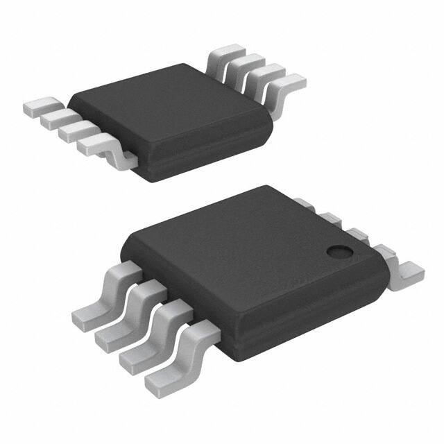
Pin connections (top view)
Description
The TSC103 measures a small differential voltage on a high-side shunt resistor and translates it into a ground-referenced output voltage. The gain is adjustable to four different values from 20 V/V up to 100 V/V by two selection pins. Wide input common-mode voltage range, low quiescent current, and tiny TSSOP8 packaging enable use in a wide variety of applications.
January 2010
Doc ID 16873 Rev 1
1/23
www.st.com 23
�Contents
TSC103
Contents
1 2 3 4 Application schematic and pin description . . . . . . . . . . . . . . . . . . . . . . 3 Absolute maximum ratings and operating conditions . . . . . . . . . . . . . 6 Electrical characteristics . . . . . . . . . . . . . . . . . . . . . . . . . . . . . . . . . . . . . 7 Parameter definitions . . . . . . . . . . . . . . . . . . . . . . . . . . . . . . . . . . . . . . . 10
4.1 4.2 4.3 4.4 4.5 4.6 Common mode rejection ratio (CMR) . . . . . . . . . . . . . . . . . . . . . . . . . . . . 10 Supply voltage rejection ratio (SVR) . . . . . . . . . . . . . . . . . . . . . . . . . . . . 10 Gain (Av) and input offset voltage (Vos) . . . . . . . . . . . . . . . . . . . . . . . . . . 10 Output voltage drift versus temperature . . . . . . . . . . . . . . . . . . . . . . . . . . 12 Input offset drift versus temperature . . . . . . . . . . . . . . . . . . . . . . . . . . . . . 13 Output voltage accuracy . . . . . . . . . . . . . . . . . . . . . . . . . . . . . . . . . . . . . . 13
5 6 7
Maximum permissible voltages on pins . . . . . . . . . . . . . . . . . . . . . . . . 15 Application information . . . . . . . . . . . . . . . . . . . . . . . . . . . . . . . . . . . . . 16 Package information . . . . . . . . . . . . . . . . . . . . . . . . . . . . . . . . . . . . . . . . 18
7.1 7.2 SO-8 package information . . . . . . . . . . . . . . . . . . . . . . . . . . . . . . . . . . . . 19 TSSOP-8 package information . . . . . . . . . . . . . . . . . . . . . . . . . . . . . . . . . 20
8 9
Ordering information . . . . . . . . . . . . . . . . . . . . . . . . . . . . . . . . . . . . . . . 21 Revision history . . . . . . . . . . . . . . . . . . . . . . . . . . . . . . . . . . . . . . . . . . . 22
2/23
Doc ID 16873 Rev 1
�TSC103
Application schematic and pin description
1
Application schematic and pin description
The TSC103 high-side current sense amplifier can be used in either single- or dual-supply mode. In the single-supply configuration, the TSC103 features a wide 2.9 V to 70 V input common-mode range totally independent of the supply voltage. In the dual-supply range, the common-mode range is shifted by the value of the negative voltage applied on the Vccpin. For instance, with Vcc+ = 5 V and Vcc- = -5 V, then the input common-mode range is -2 V to 65 V. Figure 1. Single-supply configuration schematic
Vsense Iload load Rsense
Common-mode voltage: 2.9 V to 70 V
5V
Vp
Vm
Vcc+
Vcc
µ Controller
Out
Vout
ADC
SEL1
GPIO1 GPIO2 Gnd
TSC103
VccGnd
SEL2
AM04517
Doc ID 16873 Rev 1
3/23
�Application schematic and pin description Figure 2. Dual-supply configuration schematic
Vsense Iload load Rsense
TSC103
Common-mode voltage: -2 V to 65 V
5V
Vp
Vm
Vcc+
Vcc
µ Controller
Out
Vout
ADC
SEL1
GPIO1 GPIO2 Gnd
TSC103
VccGnd
SEL2
-5 V
AM04518
4/23
Doc ID 16873 Rev 1
�TSC103 Figure 3.
Application schematic and pin description Common-mode versus supply voltage in dual-supply configuration
Vicm common-mode voltage operating range Max = 70 V Max = 65 V Max = 60 V
min = 2.9 V min = -2.1 V min = -7.1 V Vcc- = -10 V
Vcc- = 0 V Single-supply
Vcc- = -5 V
Dual-supply
AM04519
Table 1 describes the function of each pin. Their position is shown in the illustration on the cover page and in Figure 1 on page 3. Table 1.
Symbol Out Gnd Vcc+ VccVp Vm SEL1 SEL2
Pin description
Type Analog output Power supply Power supply Power supply Analog input Analog input Digital input Digital input Function The Out voltage is proportional to the magnitude of the sense voltage Vp-Vm. Ground line. Positive power supply line. Negative power supply line. Connection for the external sense resistor. The measured current enters the shunt on the Vp side. Connection for the external sense resistor. The measured current exits the shunt on the Vm side. Gain-select pin. Gain-select pin.
Doc ID 16873 Rev 1
5/23
�Absolute maximum ratings and operating conditions
TSC103
2
Absolute maximum ratings and operating conditions
Table 2.
Symbol Vid Vin_sense Vin_sel Vcc+ Vcc+-VccVout Tstg Tj Rthja
Absolute maximum ratings
Parameter Input pins differential voltage (Vp-Vm) Sensing pins input voltages (Vp, Vm) Positive supply voltage(2) DC supply voltage DC output pin voltage(2)
(1) (2)
Value ±20 -16 to 75 -0.3 to Vcc++0.3 -0.3 to 7 0 to 15 -0.3 to Vcc++0.3 -55 to 150 150 120 125 2.5 150 1.5
Unit V V V V V V °C °C °C/W °C/W kV V kV
Gain selection pins input voltages (SEL1, SEL2)
Storage temperature Maximum junction temperature TSSOP8 thermal resistance junction to ambient SO-8 thermal resistance junction to ambient HBM: human body model(3)
ESD
MM: machine model(4) CDM: charged device model(5)
1. These voltage values are measured with respect to the Vcc- pin. 2. These voltage values are measured with respect to the Gnd pin. 3. Human body model: a 100 pF capacitor is charged to the specified voltage, then discharged through a 1.5 kΩ resistor between two pins of the device. This is done for all couples of connected pin combinations while the other pins are floating. 4. Machine model: a 200 pF capacitor is charged to the specified voltage, then discharged directly between two pins of the device with no external series resistor (internal resistor < 5 Ω). This is done for all couples of connected pin combinations while the other pins are floating. 5. Charged device model: all pins plus package are charged together to the specified voltage and then discharged directly to ground.
Table 3.
Symbol Vcc+
Operating conditions
Parameter Supply voltage in single-supply configuration from Tmin to Tmax (Vcc- connected to Gnd = 0 V) Negative supply voltage in dual-supply configuration from Tmin to Tmax Value 2.7 to 5.5 Unit V
Vcc-
Vcc+ = 5.5 V max Vcc+ = 3 V max
-8 to 0 -11 to 0 2.9 to 70 -40 to 125
V V V °C
Vicm Toper
Common-mode voltage range referred to pin Vcc (Tmin to Tmax) Operational temperature range (Tmin to Tmax)
6/23
Doc ID 16873 Rev 1
�TSC103
Electrical characteristics
3
Electrical characteristics
The electrical characteristics given in the following tables are measured under the following test conditions unless otherwise specified.
● ●
Tamb = 25° C, Vcc+ = 5 V, Vcc- connected to Gnd (single-supply configuration). Vsense = Vp-Vm = 50 mV, Vm = 12 V, no load on Out, all gain configurations.
Table 4.
Symbol ICC ICC1
Supply
Parameter Total supply current Total supply current Test conditions Vsense = 0 V, Tmin < Tamb < Tmax Vsense = 50 mV Av = 50 V/V Tmin < Tamb < Tmax Min. Typ. 200 300 Max. 360 480 Unit µA µA
Table 5.
Symbol
Input
Parameter Test conditions 2.9 V< Vm < 70 V Tmin < Tamb < Tmax Av = 50 V/V or 100 V/V 2.9 V< Vm < 30 V 1 kHz sine wave 2.7 V< VCC < 5.5 V Vsense = 30 mV Tmin < Tamb < Tmax Tamb = 25° C Tmin < Tamb < Tmax Av = 50 V/V Tmin < Tamb < Tmax VCC = 0 V Tmin < Tamb < Tmax Vsense = 0 V Tmin < Tamb < Tmax 10 -0.3 1.2 400 -20 Min. 90 Typ. 105 Max. Unit dB
DC common-mode rejection DC CMR Variation of Vout versus Vicm referred to input(1) AC common-mode rejection Variation of Vout versus Vicm AC CMR referred to input (peak-to-peak voltage variation) SVR Supply voltage rejection Variation of Vout versus VCC(2) SEL1 = Gnd, SEL2 = Gnd Input offset voltage(3) Input offset drift vs. T Input leakage current Input bias current Logic low voltage threshold (SEL1 and SEL2)
95
dB
85
100 ±500 ±1100 +5 1 15 0.5 VCC
dB
Vos dVos/dT Ilk Iib VIL VIH Isel
µV µV/°C µA µA V V nA
VCCmin < VCC < VCCmax
Tmin < Tamb < Tmax
Logic high voltage threshold (SEL1 VCCmin < VCC < VCCmax and SEL2) Tmin < Tamb < Tmax Gain-select pins (SEL1 and SEL2) SEL pin connected to GND or input bias current VCC Tmin < Tamb < Tmax
1. See Chapter 4: Parameter definitions on page 10 for the definition of CMR. 2. See Chapter 4 for the definition of SVR. 3. See Chapter 4 for the definition of Vos.
Doc ID 16873 Rev 1
7/23
�Electrical characteristics Table 6.
Symbol
TSC103
Output
Parameter Test conditions SEL1 = Gnd, SEL2 = Gnd SEL1 = Gnd, SEL2 = Vcc+ SEL1 = Vcc+, SEL2 = Gnd SEL1 = Vcc+, SEL2 = Vcc+ Av = 50 V/V Tmin < Tamb < Tmax -10 mA < Iout
很抱歉,暂时无法提供与“TSC103IYPT”相匹配的价格&库存,您可以联系我们找货
免费人工找货- 国内价格 香港价格
- 4000+15.675624000+1.89980


 工商网监
湘ICP备2023018690号
工商网监
湘ICP备2023018690号
