VIPER222
Datasheet
High voltage converter
Features
•
•
•
•
•
730 V avalanche rugged power MOSFET
PWM controller
1.2 V reference voltage
Frequency jittering
40 mW no load input power at 230 VAC
•
•
Short-circuit protection
Thermal shutdown
Application
•
Auxiliary SMPS for home appliances, consumer, industrial, lighting.
Description
The VIPER222 device is a high performance high voltage converter that combines a
730 V rugged power MOSFET with a PWM control. The device embeds the high
voltage startup and the current sense circuit, avoiding the use of extra components in
the BoM. Frequency jittering spreads the EMI and allows the use of a small filter. The
burst mode technique allows to obtain a very low input power consumption at light
load.
Figure 1. Block diagram
Product status link
Vcc
DRAIN
VIPER222
Product label
Istart-up
OSCILLATOR
SOFT
START
S
PWM
OCP
BLOCK
LOGIC
Q
R
DIS
-
EA-IN
+
1.2V
E/A
Rsense
PROTECTIONS
EA-OUT
DS13192 - Rev 2 - January 2020
For further information contact your local STMicroelectronics sales office.
GND
www.st.com
�VIPER222
Pin setting
1
Pin setting
Figure 2. Connection diagram
GND
1
10
DRAIN
VCC
2
9
DRAIN
NC
3
8
DRAIN
EA-IN
4
7
DRAIN
EA-OUT
5
6
DRAIN
Table 1. Pin description
DS13192 - Rev 2
SSOP10
Name
1
GND
Connected to the source of the internal power MOSFET and controller ground
reference.
2
VCC
Supply voltage of the control section. This pin provides the charging current of the
external capacitor.
3
NC
4
EA-IN
5
EA-OUT
6-10
DRAIN
Function
Not connected. The pin must be connected to GND pin.
Input of the error amplifier.
Output of the error amplifier.
High voltage drain pin. The start-up bias current is drawn from this pin too. Connect
to a PCB copper area to facilitate the heat dissipation.
page 2/20
�VIPER222
Typical power capability
2
Typical power capability
Table 2. Typical power
VIN: 230 VAC
VIN: 85 - 265 VAC
Adapter (1)
Open frame (2)
Adapter (1)
Open frame (2)
11 W
13 W
7W
8W
1. Typical continuous power in non-ventilated enclosed adapter measured at 50 °C ambient.
2. Maximum practical continuous power in an open frame design at 50 °C ambient, with adequate heat-sinking
DS13192 - Rev 2
page 3/20
�VIPER222
Electrical and thermal ratings
3
Electrical and thermal ratings
Table 3. Absolute maximum rating
Symbol
Pin
VDS
6-10
Drain-to-source (ground) voltage
ID
6-10
Pulse drain current (limited by TJ = 150 °C)
VEA-IN
4
Input pin voltage
VEA-OUT
5
VCC
ICC
PTOT
TJ
TSTG
Parameter
Value
Min.
Max.
Unit
730
V
2
A
-0.3
4.8
V
Out pin voltage
-0.3
4.8
V
2
Supply voltage
-0.3
Self
limited
V
2
Input current
45
mA
Power dissipation at TAMB < 50 °C
1(1)
W
Junction temperature range
-40
150
°C
Storage temperature
-55
150
°C
1. When mounted on a standard single side FR4 board with 100 mm² (0.1552 inch) of Cu (35 μm thick)..
Table 4. Thermal data
Symbol
RTH-JC
RTH-JC
RTH-JC
RTH-JC
Parameter
Thermal resistance junction to case (1)
(Dissipated power = 1 W)
Thermal resistance junction ambient (1)
(Dissipated power = 1 W)
Thermal resistance junction to case (2)
(Dissipated power = 1 W)
Thermal resistance junction ambient (2)
(Dissipated power = 1 W)
Max. value
Unit
10
°C/W
155
°C/W
5
°C/W
95
°C/W
1. When mounted on a standard single side FR4 board with minimum copper area.
2. When mounted on a standard single side FR4 board with 100 mm2 (0.155sq in) of Cu (35 μm thick).
DS13192 - Rev 2
page 4/20
�VIPER222
Electrical and thermal ratings
Figure 3. Rth vs. area
RTHjA/(RTHjA@A=100 mm2)
1.75
1.625
1.5
1.375
1.25
1.125
1
0.875
0.75
0
25
50
75
100
125
150
175
200
A(mm2)
DS13192 - Rev 2
page 5/20
�VIPER222
Electrical characteristics
4
Electrical characteristics
(TJ = 25 °C, VCC = 9 V; unless otherwise specified)
Table 5. Electrical characteristics
Symbol
Parameter
VBVDSS
Breakdown voltage
RDS(on)
Drain-Source ON state resistance
Test Condition
ID = 1 mA,
EA-OUT= GND
Typ.
VDRAIN = 100 V
IDSS
OFF state DRAIN leakage current
VDRAIN = 730 V
15
13
Startup charging current
ICH2
Charging current during operation
ICH3
Charging current during self-supply
VCC
Operating voltage range
VDRAIN = 100 V
VCC=0 V
VDRAIN = 100 V
VCC = 6 V
VDRAIN = 100 V
VCC = 6 V
ICC = 35 mA
Ω
pF
50
µA
30
V
-0.6
-1.4
mA
-2
-4
mA
-6
-9
mA
4.5
30
V
Drain-source start voltage
ICH1
Unit
V
TJ = 25 °C
Effective (energy related) output
capacitance
Max.
730
ID = 0.2 A;
COSS
VSTART
Min.
VCLAMP
VCC clamp voltage
VON
VCC ON threshold
15
16
17
V
VCCL
VCC low value
4
4.25
4.5
V
VOFF
UVLO
3.75
4
4.25
V
ICC0
Operating supply current, not switching
0.5
mA
30
V
Not switching
VDS = 150 V
VEA-OUT = 1.2 V
ICC1
Operating supply current, switching
1.3
FOSC = 30 kHz
VDS = 150 V
VEA-OUT = 1.2 V
1.6
mA
FOSC = 60 kHz
ICC_FAIL
ILIM
Drain current limit (OCP)
30
TJ =25 °C
TJ = 25 °C
mA
0.59
0.62
0.65
A
105
130
155
mA
ILIM_BM
Drain current limit at low load
TON(MIN)
Minimum turn ON time
350
ns
tRESTART
Restart time after fault
1.2
s
Overload delay time
55
ms
tOVL
DS13192 - Rev 2
VCC clamp protection
VEA-OUT = VEA_BM
page 6/20
�VIPER222
Electrical characteristics
Symbol
Parameter
Test Condition
Min.
Typ.
VIPER222XSTR
tOVLmax
Maximum overload delay
FOSC = FOSCmin
time
VIPER222LSTR
tCC_FAIL
FOSC
FOSCmin
Soft-start time
5
Clamp time before shutdown
Switching frequency
Unit
220
ms
440
FOSC = FOSCmin
tSS
Max.
11
ms
µs
325
500
675
VIPER222XSTR
27
30
33
VIPER222LSTR
54
60
66
13.5
15
16.5
Minimum switching
frequency
kHz
kHz
FD
Modulation depth
(1)
±7
kHz
FM
Modulationfrequency
(1)
260
Hz
DMAX
Max. duty cycle
(1)
VREF
E/A reference voltage
IPULL UP
EA-IN pin current pull-up
GM
E/A Trans conductance
VEA-SAT
EA-OUT pin saturation limit
VEA-BM
Burstmode threshold
RDYN
Dynamic resistance
HEA-OUT
ΔVEA-OUT / ΔID
IEA-OUT
EA-OUT pin source / sink current
TSD
Thermal shutdown temperature
70
1.175
(1)
VEA-OUT =2.7V
VEA-IN =GND
(1)
(1)
1.2
%
1.225
V
-1
µA
0.5
mA/V
3
V
0.8
V
65
kΩ
3.8
150
80
7
V/A
100
µA
160
°C
1. Specification assured by characterization.
DS13192 - Rev 2
page 7/20
�VIPER222
Typical electrical characteristics
5
Typical electrical characteristics
Figure 4. IFIG
LIM vs.
4 TJ
Figure 5. VREF vs. TJ
VREF/(VREF@25°C)
ILIM/(ILIM@25°C)
1.15
1.01
1.1
1.005
1.05
1
1
0.995
0.95
0.99
0.9
-50
-25
0
25
50
75
100
125
-50
150
-25
0
25
50
75
100
125
150
100
125
150
Tj(°C)
Tj(°C)
Figure 6. ICC0 vs. TJ
Figure 7. ICC1 vs. TJ
ICC0/(ICC0@25°C)
ICC1/(ICC1@25°C)
1.5
1.2
1.3
1.1
1.1
1
0.9
0.9
0.7
0.8
-50
-25
0
25
50
75
100
125
150
-50
-25
0
Tj(°C)
25
50
75
Tj(°C)
Figure 9. VBVDSS vs. Tj
Figure 8. RDS(on) vs. TJ
RDS(on)/(RDS(on)@25°C)
1.2
VBVDSS/(VBVDSS@25°C)
2.5
2
1.1
1.5
1
1
0.5
0
-50
-25
0
25
50
Tj(°C)
DS13192 - Rev 2
75
100
125
150
0.9
-50
0
50
100
150
Tj(°C)
page 8/20
�VIPER222
General description
6
General description
VIPER222 is a 730 V high voltage converter optimized for flyback and buck topologies that operates at 60 kHz
(L type) or 30 kHz (X type) switching frequency and integrates the jittering feature in order to reduce the EMI
level.
The low IC consumption combined with the burst mode technique allow to obtain very low input power at no load
and very good efficiency at light load.
6.1
Startup
At the first startup the integrated high voltage current source charges the VCC capacitor. At the beginning of
startup, when the capacitor is fully discharged, the charging current is low, ICH1, in order to avoid IC damaging in
case VCC is accidentally shorted to GND. As VCC exceeds 1 V, ICH1 is increased to ICH2 in order to speed up the
charging. The charge current is stopped as soon as VCC reaches VON.
As soon as the VCC capacitor is charged up to VON, the high voltage current source is disabled, the device is
powered by the energy stored in the capacitor and the primary MOSFET starts switching.
The internal soft-start function of the device progressively increases the cycle-by-cycle current limitation set point
from zero up to ILIM in 8 steps. The soft-start time, tSS, is internally set at 8 ms. This function is activated at any
attempt of converter startup and at any restart after a fault event.
6.2
Feedback loop
The device operates in current mode, so the primary current is internally sensed and converted in voltage that is
applied to the non-inverting pin of the PWM comparator. The sensed voltage is compared through a voltage
divider and on cycle-by-cycle basis with the one present on the EA-IN pin.
The OCP comparator works in parallel with the PWM comparator and it limits the primary current below
the ILIM threshold.
There are two ways to close the loop and get the output regulated: through resistor divider or through external
error amplifier plus optocoupler
Resistor divider
For non-isolated topologies (fly-back, buck or buck-boost converters) the output voltage can be directly set
connecting a resistor divider (referenced to GND pin) between the converter output and the EA-IN pin, which is
the inverting input of the integrated error amplifier (EA).
Primary side regulation can be realized connecting the resistor divider between VCC, EA-IN and GND pins.
The loop compensation network is connected across EA-OUT and GND pins.
External error amplifier plus optocoupler
In case of isolated fly-back, EA-IN must be connected to GND, which disables the internal error amplifier, and the
output voltage is set through an external error amplifier (TL431 or similar) placed on the secondary side. Its error
signal, reported to the primary through an optocoupler, is used to set the EA-OUT pin voltage to the value
corresponding to the DRAIN peak current required by the control loop to deliver the given output power.
The EA-OUT pin dynamics range between the values VEA-BM and VEA-SAT: below the VEA-BM level the device
enters burst mode; above the VEA-SAT level, the primary drain current reaches its limit ILIM.
6.3
Pulse skipping
The protection is intended to avoid the so called “flux-runaway” condition often present at converter startup,
because of the low output voltage, and due to the fact that the primary MOSFET, cannot be turned off before the
minimum on-time. During the on-time, the inductor is charged by the input voltage and if it cannot be discharged
by the same amount during the off-time, in every switching cycle there is a net increase of the average inductor
current, that can reach dangerously high values.
DS13192 - Rev 2
page 9/20
�VIPER222
Burst mode at light load
Thanks to this protection, each time the DRAIN peak current exceeds ILIM level within tON_MIN, one switching
cycle is skipped. The cycles can be skipped until the minimum switching frequency FOSCmin (15 kHz typ.) is
reached. Each time the DRAIN peak current does not exceed ILIM within tON_MIN, one switching cycle is restored.
The cycles can be restored until the nominal switching frequency is reached, FOSC (30 or 60 kHz).
6.4
Burst mode at light load
When the load decreases, the feedback loop reacts lowering the EA-OUT pin voltage. If it goes below the VEA-BM
threshold, the DRAIN peak current is reduced to ILIM_BM, avoiding audible noise which could arise from low
switching frequency. When the load is increased, VEA_OUT increases. As it reaches the VEA_SAT threshold, the
DRAIN peak current reaches its maximum value, ILIM.
6.5
Short-circuit protection
In case of overload or short-circuit on the output, the IC runs at ILIM.
If this condition is removed before 50ms, the IC continues its normal operation.
If this condition lasts for tOVL (50ms, typ.), the protection is tripped, the device stops switching for tRESTART (1 sec.
typ.), then resumes switching with soft-start phase. If the fault is still present, after tOVL, the IC is disabled again
for tRESTART; otherwise it resumes normal operation.
If the converter is definitively operated at FOSC_MIN, (see Section 6.3 ), the overload time will increase to
tOVL_MAX (100 ms typ. for VIPER222XSTR; 200 ms typ. for VIPER222LSTR).
During the fault event, the VCC voltage is maintained between VCCL (4.25 V) and VON (16 V) by the periodical
activation of the high voltage current source.
6.6
VCC clamp protection
If VCC reaches the clamp level VCLAMP and the current injected into the pin exceeds the internal threshold
ICC_FAIL for more than tCC_FAIL, a fault condition is detected. The PWM is disabled for tRESTART and then activated
again in soft-start phase. The protection is disabled during the soft-start time.
DS13192 - Rev 2
page 10/20
�VIPER222
Basic application schematics
7
Basic application schematics
Figure 10. Non isolated flyback converter
Figure 11. Primary side flyback converter
DS13192 - Rev 2
page 11/20
�VIPER222
Basic application schematics
Figure 12. Isolated flyback converter
Figure 13. Buck converter
Figure 14. Buck-Boost converter
~ AC
Din
Rin
Daux
VIPer222
VCC
DRAIN
R1
EA-IN
CONTROL
C2
Cvcc
EA-OUT
Cin
Cea_out2
GND
R2
D2
Cea_out1
Rea_out1
Vout (< 0V)
Dout
Lout
Cout
GROUND
DS13192 - Rev 2
page 12/20
�VIPER222
Package information
8
Package information
In order to meet environmental requirements, ST offers these devices in different grades of ECOPACK®
packages, depending on their level of environmental compliance. ECOPACK® specifications, grade definitions
and product status are available at: www.st.com.
ECOPACK® is an ST trademark.
8.1
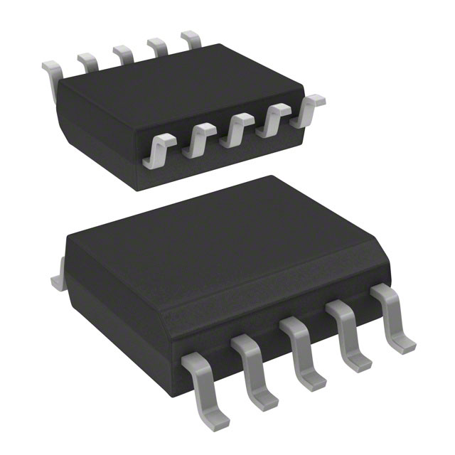
SSOP10 package information
Figure 15. SSOP10 package outline
DS13192 - Rev 2
page 13/20
�VIPER222
SSOP10 package information
Table 6. SSO10 mechanical data
Dim.
mm
Min.
Typ.
A
Max.
1.75
A1
0.10
A2
1.25
b
0.31
0.51
c
0.17
0.25
D
4.80
4.90
5
E
5.80
6
6.20
E1
3.80
3.90
4
e
0.25
1
H
0.25
0.50
L
0.40
0.90
K
0°
8°
Figure 16. SSOP10 recommended footprint
DS13192 - Rev 2
page 14/20
�VIPER222
SSOP10 package information
Table 7. Ordering information
Order code
DS13192 - Rev 2
Package
Packaging
VIPER222XSTR
SSOP10
Tape & Reel
VIPER222LSTR
SSOP10
Tape & Reel
page 15/20
�VIPER222
Revision history
Table 8. Document revision history
DS13192 - Rev 2
Date
Version
Changes
20-Dec-2019
1
Initial release.
17-Jan-2020
2
Changed min value ILIM parameter in Table 5
page 16/20
�VIPER222
Contents
Contents
1
Pin setting. . . . . . . . . . . . . . . . . . . . . . . . . . . . . . . . . . . . . . . . . . . . . . . . . . . . . . . . . . . . . . . . . . . . . . . . .2
2
Typical power capability . . . . . . . . . . . . . . . . . . . . . . . . . . . . . . . . . . . . . . . . . . . . . . . . . . . . . . . . . . . 3
3
Electrical and thermal ratings . . . . . . . . . . . . . . . . . . . . . . . . . . . . . . . . . . . . . . . . . . . . . . . . . . . . . . 4
4
Electrical characteristics. . . . . . . . . . . . . . . . . . . . . . . . . . . . . . . . . . . . . . . . . . . . . . . . . . . . . . . . . . . 6
5
Typical electrical characteristics . . . . . . . . . . . . . . . . . . . . . . . . . . . . . . . . . . . . . . . . . . . . . . . . . . . 8
6
General description. . . . . . . . . . . . . . . . . . . . . . . . . . . . . . . . . . . . . . . . . . . . . . . . . . . . . . . . . . . . . . . .9
6.1
Startup . . . . . . . . . . . . . . . . . . . . . . . . . . . . . . . . . . . . . . . . . . . . . . . . . . . . . . . . . . . . . . . . . . . . . . . 9
6.2
Feedback loop . . . . . . . . . . . . . . . . . . . . . . . . . . . . . . . . . . . . . . . . . . . . . . . . . . . . . . . . . . . . . . . . . 9
6.3
Pulse skipping . . . . . . . . . . . . . . . . . . . . . . . . . . . . . . . . . . . . . . . . . . . . . . . . . . . . . . . . . . . . . . . . . 9
6.4
Burst mode at light load . . . . . . . . . . . . . . . . . . . . . . . . . . . . . . . . . . . . . . . . . . . . . . . . . . . . . . . . 10
6.5
Short-circuit protection . . . . . . . . . . . . . . . . . . . . . . . . . . . . . . . . . . . . . . . . . . . . . . . . . . . . . . . . . 10
6.6
VCC clamp protection. . . . . . . . . . . . . . . . . . . . . . . . . . . . . . . . . . . . . . . . . . . . . . . . . . . . . . . . . . 10
7
Basic application schematics . . . . . . . . . . . . . . . . . . . . . . . . . . . . . . . . . . . . . . . . . . . . . . . . . . . .11
8
Package information. . . . . . . . . . . . . . . . . . . . . . . . . . . . . . . . . . . . . . . . . . . . . . . . . . . . . . . . . . . . . .13
8.1
[Package name] package information . . . . . . . . . . . . . . . . . . . . . . . . . . . . . . . . . . . . . . . . . . . . 13
Revision history . . . . . . . . . . . . . . . . . . . . . . . . . . . . . . . . . . . . . . . . . . . . . . . . . . . . . . . . . . . . . . . . . . . . . . .16
Contents . . . . . . . . . . . . . . . . . . . . . . . . . . . . . . . . . . . . . . . . . . . . . . . . . . . . . . . . . . . . . . . . . . . . . . . . . . . . . .17
List of tables . . . . . . . . . . . . . . . . . . . . . . . . . . . . . . . . . . . . . . . . . . . . . . . . . . . . . . . . . . . . . . . . . . . . . . . . . .18
List of figures. . . . . . . . . . . . . . . . . . . . . . . . . . . . . . . . . . . . . . . . . . . . . . . . . . . . . . . . . . . . . . . . . . . . . . . . . .19
DS13192 - Rev 2
page 17/20
�VIPER222
List of tables
List of tables
Table 1.
Table 2.
Table 3.
Table 4.
Table 5.
Table 6.
Table 7.
Table 8.
Pin description. . . . . . . . .
Typical power . . . . . . . . .
Absolute maximum rating .
Thermal data. . . . . . . . . .
Electrical characteristics . .
SSO10 mechanical data . .
Ordering information. . . . .
Document revision history .
DS13192 - Rev 2
.
.
.
.
.
.
.
.
.
.
.
.
.
.
.
.
.
.
.
.
.
.
.
.
.
.
.
.
.
.
.
.
.
.
.
.
.
.
.
.
.
.
.
.
.
.
.
.
.
.
.
.
.
.
.
.
.
.
.
.
.
.
.
.
.
.
.
.
.
.
.
.
.
.
.
.
.
.
.
.
.
.
.
.
.
.
.
.
.
.
.
.
.
.
.
.
.
.
.
.
.
.
.
.
.
.
.
.
.
.
.
.
.
.
.
.
.
.
.
.
.
.
.
.
.
.
.
.
.
.
.
.
.
.
.
.
.
.
.
.
.
.
.
.
.
.
.
.
.
.
.
.
.
.
.
.
.
.
.
.
.
.
.
.
.
.
.
.
.
.
.
.
.
.
.
.
.
.
.
.
.
.
.
.
.
.
.
.
.
.
.
.
.
.
.
.
.
.
.
.
.
.
.
.
.
.
.
.
.
.
.
.
.
.
.
.
.
.
.
.
.
.
.
.
.
.
.
.
.
.
.
.
.
.
.
.
.
.
.
.
.
.
.
.
.
.
.
.
.
.
.
.
.
.
.
.
.
.
.
.
.
.
.
.
.
.
.
.
.
.
.
.
.
.
.
.
.
.
.
.
.
.
.
.
.
.
.
.
.
.
.
.
.
.
.
.
.
.
.
.
.
.
.
.
.
.
.
.
.
.
.
.
.
.
.
.
.
.
.
.
.
.
.
.
.
.
.
.
.
.
.
.
.
.
.
.
.
.
.
.
.
.
.
.
.
.
.
.
.
.
.
.
.
.
.
.
.
.
.
.
.
.
.
.
.
.
.
.
.
.
.
.
.
.
.
.
.
.
.
.
.
.
.
.
.
.
.
.
.
.
.
.
.
.
.
.
.
.
.
.
.
.
.
.
.
.
.
.
.
.
.
.
.
.
.
.
.
.
.
.
.
.
.
.
.
.
.
.
.
.
.
.
.
.
.
.
.
.
.
.
.
.
.
.
.
.
.
.
.
.
.
.
.
.
.
.
.
.
.
.
.
.
.
.
.
.
.
.
.
.
.
.
.
.
.
.
.
.
.
.
. 2
. 3
. 4
. 4
. 6
14
15
16
page 18/20
�VIPER222
List of figures
List of figures
Figure 1.
Figure 2.
Figure 3.
Figure 4.
Figure 5.
Figure 6.
Figure 7.
Figure 8.
Figure 9.
Figure 10.
Figure 11.
Figure 12.
Figure 13.
Figure 14.
Figure 15.
Figure 16.
DS13192 - Rev 2
Block diagram . . . . . . . . . . . . .
Connection diagram . . . . . . . . .
Rth vs. area . . . . . . . . . . . . . . .
ILIM vs. TJ . . . . . . . . . . . . . . . .
VREF vs. TJ . . . . . . . . . . . . . . .
ICC0 vs. TJ . . . . . . . . . . . . . . . .
ICC1 vs. TJ . . . . . . . . . . . . . . . .
RDS(on) vs. TJ . . . . . . . . . . . . . .
VBVDSS vs. Tj . . . . . . . . . . . . . .
Non isolated flyback converter . .
Primary side flyback converter . .
Isolated flyback converter . . . . .
Buck converter . . . . . . . . . . . . .
Buck-Boost converter . . . . . . . .
SSOP10 package outline . . . . . .
SSOP10 recommended footprint.
.
.
.
.
.
.
.
.
.
.
.
.
.
.
.
.
.
.
.
.
.
.
.
.
.
.
.
.
.
.
.
.
.
.
.
.
.
.
.
.
.
.
.
.
.
.
.
.
.
.
.
.
.
.
.
.
.
.
.
.
.
.
.
.
.
.
.
.
.
.
.
.
.
.
.
.
.
.
.
.
.
.
.
.
.
.
.
.
.
.
.
.
.
.
.
.
.
.
.
.
.
.
.
.
.
.
.
.
.
.
.
.
.
.
.
.
.
.
.
.
.
.
.
.
.
.
.
.
.
.
.
.
.
.
.
.
.
.
.
.
.
.
.
.
.
.
.
.
.
.
.
.
.
.
.
.
.
.
.
.
.
.
.
.
.
.
.
.
.
.
.
.
.
.
.
.
.
.
.
.
.
.
.
.
.
.
.
.
.
.
.
.
.
.
.
.
.
.
.
.
.
.
.
.
.
.
.
.
.
.
.
.
.
.
.
.
.
.
.
.
.
.
.
.
.
.
.
.
.
.
.
.
.
.
.
.
.
.
.
.
.
.
.
.
.
.
.
.
.
.
.
.
.
.
.
.
.
.
.
.
.
.
.
.
.
.
.
.
.
.
.
.
.
.
.
.
.
.
.
.
.
.
.
.
.
.
.
.
.
.
.
.
.
.
.
.
.
.
.
.
.
.
.
.
.
.
.
.
.
.
.
.
.
.
.
.
.
.
.
.
.
.
.
.
.
.
.
.
.
.
.
.
.
.
.
.
.
.
.
.
.
.
.
.
.
.
.
.
.
.
.
.
.
.
.
.
.
.
.
.
.
.
.
.
.
.
.
.
.
.
.
.
.
.
.
.
.
.
.
.
.
.
.
.
.
.
.
.
.
.
.
.
.
.
.
.
.
.
.
.
.
.
.
.
.
.
.
.
.
.
.
.
.
.
.
.
.
.
.
.
.
.
.
.
.
.
.
.
.
.
.
.
.
.
.
.
.
.
.
.
.
.
.
.
.
.
.
.
.
.
.
.
.
.
.
.
.
.
.
.
.
.
.
.
.
.
.
.
.
.
.
.
.
.
.
.
.
.
.
.
.
.
.
.
.
.
.
.
.
.
.
.
.
.
.
.
.
.
.
.
.
.
.
.
.
.
.
.
.
.
.
.
.
.
.
.
.
.
.
.
.
.
.
.
.
.
.
.
.
.
.
.
.
.
.
.
.
.
.
.
.
.
.
.
.
.
.
.
.
.
.
.
.
.
.
.
.
.
.
.
.
.
.
.
.
.
.
.
.
.
.
.
.
.
.
.
.
.
.
.
.
.
.
.
.
.
.
.
.
.
.
.
.
.
.
.
.
.
.
.
.
.
.
.
.
.
.
.
.
.
.
.
.
.
.
.
.
.
.
.
.
.
.
.
.
.
.
.
.
.
.
.
.
.
.
.
.
.
.
.
.
.
.
.
.
.
.
.
.
.
.
.
.
.
.
.
.
.
.
.
.
.
.
.
.
.
.
.
.
.
.
.
.
.
.
.
.
.
.
.
.
.
.
.
.
.
.
.
.
.
.
.
.
.
.
.
.
.
.
.
.
.
.
.
.
.
.
.
.
.
.
.
.
.
.
.
.
.
.
.
.
.
.
.
.
.
.
.
.
.
.
.
.
.
.
.
.
.
.
.
.
.
.
.
.
.
.
.
.
.
.
.
.
.
.
.
.
.
.
.
.
.
.
.
.
.
.
.
.
.
.
.
.
.
.
.
.
.
.
.
.
.
.
.
.
.
.
.
.
.
.
.
.
.
.
.
.
.
.
.
.
.
.
.
.
.
.
.
.
.
.
.
.
.
.
.
.
.
.
.
.
.
.
.
.
.
.
.
.
.
.
.
.
.
.
.
.
.
.
.
.
.
.
.
.
.
.
.
.
.
.
.
.
.
.
.
.
.
.
.
.
.
.
.
. 1
. 2
. 5
. 8
. 8
. 8
. 8
. 8
. 8
11
11
12
12
12
13
14
page 19/20
�VIPER222
IMPORTANT NOTICE – PLEASE READ CAREFULLY
STMicroelectronics NV and its subsidiaries (“ST”) reserve the right to make changes, corrections, enhancements, modifications, and improvements to ST
products and/or to this document at any time without notice. Purchasers should obtain the latest relevant information on ST products before placing orders. ST
products are sold pursuant to ST’s terms and conditions of sale in place at the time of order acknowledgement.
Purchasers are solely responsible for the choice, selection, and use of ST products and ST assumes no liability for application assistance or the design of
Purchasers’ products.
No license, express or implied, to any intellectual property right is granted by ST herein.
Resale of ST products with provisions different from the information set forth herein shall void any warranty granted by ST for such product.
ST and the ST logo are trademarks of ST. For additional information about ST trademarks, please refer to www.st.com/trademarks. All other product or service
names are the property of their respective owners.
Information in this document supersedes and replaces information previously supplied in any prior versions of this document.
© 2020 STMicroelectronics – All rights reserved
DS13192 - Rev 2
page 20/20
�