VN7020AJ
Datasheet
High-side driver with MultiSense analog feedback for automotive applications
Features
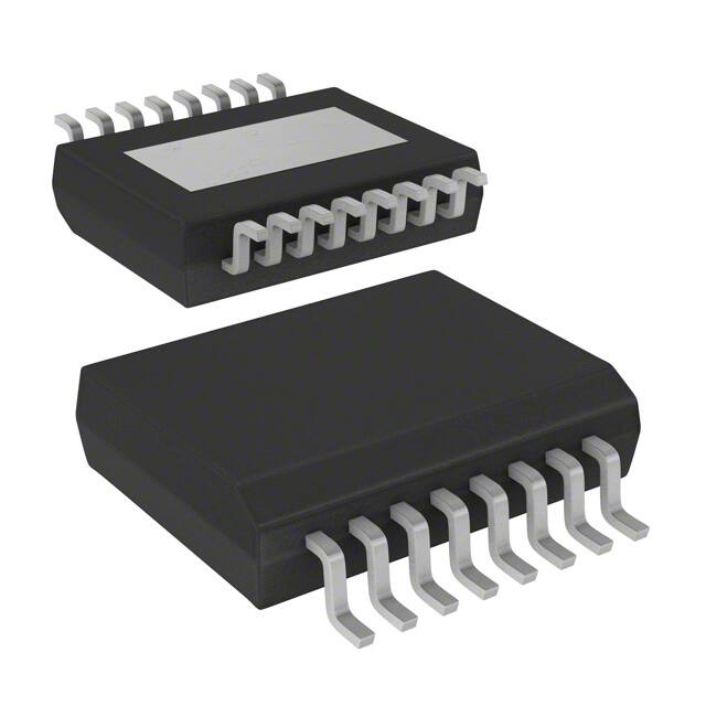
PowerSSO-16
Max transient supply voltage
VCC
40 V
Operating voltage range
VCC
4 to 28 V
Typ. on-state resistance (per Ch)
RON
20 mΩ
Current limitation (typ)
ILIMH
63 A
Standby current (max)
ISTBY
0.5 µA
•
•
•
Product status link
VN7020AJ
•
AEC-Q100 qualified
General
–
Single channel smart high-side driver with MultiSense analog feedback
–
Very low standby current
–
Compatible with 3 V and 5 V CMOS outputs
MultiSense diagnostic functions
–
Multiplexed analog feedback of: load current with high precision
proportional current mirror, VCC supply voltage and TCHIP device
temperature
–
Overload and short to ground (power limitation) indication
–
Thermal shutdown indication
–
OFF-state open-load detection
–
Output short to VCC detection
–
Sense enable/disable
Protections
–
Undervoltage shutdown
–
Overvoltage clamp
–
Load current limitation
–
Self limiting of fast thermal transients
–
Configurable latch-off on overtemperature or power limitation with
dedicated fault reset pin
–
Loss of ground and loss of VCC
–
–
Reverse battery with external components
Electrostatic discharge protection
Applications
•
•
•
All types of Automotive resistive, inductive and capacitive loads
Specially intended for automotive turn indicators (up to 2x P27W or SAE1156
and R5W paralleled or LED rear combinations)
Protected supply for ADAS systems: radars and sensors
Description
The device is a dual channel high-side driver manufactured using ST proprietary
VIPower® M0-7 technology and housed in PowerSSO-16 package. The device is
DS10831 - Rev 4 - July 2018
For further information contact your local STMicroelectronics sales office.
www.st.com
�VN7020AJ
designed to drive 12 V automotive grounded loads through a 3 V and 5 V CMOScompatible interface, providing protection and diagnostics.
The device integrates advanced protective functions such as load current limitation,
overload active management by power limitation and overtemperature shutdown with
configurable latch-off.
A FaultRST pin unlatches the output in case of fault or disables the latch-off
functionality.
A dedicated multifunction multiplexed analog output pin delivers sophisticated
diagnostic functions including high precision proportional load current sense, supply
voltage feedback and chip temperature sense, in addition to the detection of overload
and short circuit to ground, short to VCC and OFF-state open-load.
A sense enable pin allows OFF-state diagnosis to be disabled during the module lowpower mode as well as external sense resistor sharing among similar devices.
DS10831 - Rev 4
page 2/45
�VN7020AJ
Block diagram and pin description
1
Block diagram and pin description
Figure 1. Block diagram
VCC
Internal supply
VCC – GND
Clamp
Undervoltage
shut-down
Control & Diagnostic
VCC – OUT
Clamp
FaultRST
INPUT
Gate Driver
SEL1
T
VCC
VON
Limitation
SEL0
Current
Limitation
MUX
SEn
MultiSense
Power Limitation
Overtemperature
T
Short to VCC
Open-Load in OFF
Current
Sense
Fault
VSENSEH
GND
OUTPUT
GAPGCFT00328
Table 1. Pin functions
Name
VCC
OUTPUT
GND
INPUT
MultiSense
SEn
SEL0,1
FaultRST
DS10831 - Rev 4
Function
Battery connection.
Power outputs. All the pins must be connected together.
Ground connection. Must be reverse battery protected by an external diode /
resistor network.
Voltage controlled input pin with hysteresis, compatible with 3 V and 5 V CMOS
outputs. It controls output switch state.
Multiplexed analog sense output pin; it delivers a current proportional to the
selected diagnostic: load current, supply voltage or chip temperature.
Active high compatible with 3 V and 5 V CMOS outputs pin; it enables the
MultiSense diagnostic pin.
Active high compatible with 3 V and 5 V CMOS outputs pin; they address the
MultiSense multiplexer.
Active low compatible with 3 V and 5 V CMOS outputs pin; it unlatches the output
in case of fault; If kept low, sets the outputs in auto-restart mode.
page 3/45
�VN7020AJ
Block diagram and pin description
Figure 2. Configuration diagram (top view)
PowerSSO-16
INPUT
FaultRST
SEn
GND
SEL0
SEL1
MultiSense
N.C.
16
15
14
13
12
11
10
9
1
2
3
4
5
6
7
8
OUTPUT
OUTPUT
OUTPUT
OUTPUT
N.C.
N.C.
N.C.
N.C.
TAB = V CC
GAPG2901151613CFT
Table 2. Suggested connections for unused and not connected pins
Connection / pin
MultiSense
N.C.
Output
Input
SEn, SELx, FaultRST
Floating
Not allowed
X(1)
X
X
X
To ground
Through 1 kΩ resistor
X
Not allowed
Through 15 kΩ resistor
Through 15 kΩ resistor
1. X: do not care.
DS10831 - Rev 4
page 4/45
�VN7020AJ
Electrical specification
2
Electrical specification
Figure 3. Current and voltage conventions
IS
VCC
FaultRST
I SEn
I OUT
OUTPUT 0,1
CS
SEL 0
VSEn
VSEL
V OUT
I SENSE
SE n
I SEL
VFR
VCC
VFn
I FR
VSENSE
I IN
INPUT 0,1
VIN
I GND
GADG2203170950PS
Note:
VF = VOUT - VCC during reverse battery condition.
2.1
Absolute maximum ratings
Stressing the device above the rating listed in Table 3. Absolute maximum ratings may cause permanent damage
to the device. These are stress ratings only and operation of the device at these or any other conditions above
those indicated in the operating sections of this specification is not implied. Exposure to the conditions in table
below for extended periods may affect device reliability.
Table 3. Absolute maximum ratings
Symbol
Value
Unit
VCC
DC supply voltage
38
-VCC
Reverse DC supply voltage
0.3
VCCPK
Maximum transient supply voltage (ISO
16750-2:2010 Test B clamped to 40 V;
RL = 4 Ω)
40
V
VCCJS
Maximum jump start voltage for single pulse
short circuit protection
28
V
-IGND
DC reverse ground pin current
200
mA
IOUT
OUTPUT DC output current
Internally limited
-IOUT
Reverse DC output current
17
IIN
DS10831 - Rev 4
Parameter
V
A
INPUT DC input current
ISEn
SEn DC input current
ISEL
SEL0,1 DC input current
IFR
FaultRST DC input current
VFR
FaultRST DC input voltage
-1 to 10
mA
7.5
V
page 5/45
�VN7020AJ
Thermal data
Symbol
Parameter
ISENSE
EMAX
Value
MultiSense pin DC output current
(VGND = VCC and VSENSE < 0 V)
10
MultiSense pin DC output current in reverse
(VCC < 0 V)
-20
Maximum switching energy (single pulse)
(TDEMAG = 0.4 ms; Tjstart = 150 °C)
64
mJ
4000
V
2000
V
mA
Electrostatic discharge (JEDEC 22A-114F)
VESD
VESD
Tstg
2.2
•
INPUT
•
MultiSense
•
SEn, SEL0,1, FaultRST
4000
V
•
OUTPUT
4000
V
•
VCC
4000
V
750
V
Charge device model (CDM-AEC-Q100-011)
Tj
Unit
Junction operating temperature
-40 to 150
Storage temperature
-55 to 150
°C
Thermal data
Table 4. Thermal data
Symbol
Parameter
Typ. value
Rthj-board
Thermal resistance junction-board (JEDEC JESD 51-5 /
Rthj-amb
Thermal resistance junction-ambient (JEDEC JESD 51-5)(2)
57
Rthj-amb
Thermal resistance junction-ambient (JEDEC JESD 51-7)
23
51-8)(1)
Unit
5.2
°C/W
1. Device mounted on four-layers 2s2p PCB
2. Device mounted on two-layers 2s0p PCB with 2 cm2 heatsink copper trace
2.3
Main electrical characteristics
7 V < VCC < 28 V; -40°C < Tj < 150°C, unless otherwise specified.
All typical values refer to VCC = 13 V; Tj = 25°C, unless otherwise specified.
Table 5. Power section
Symbol
Parameter
Test conditions
Typ.
Max.
Unit
4
13
28
V
VCC
Operating supply voltage
VUSD
Undervoltage shutdown
4
V
Undervoltage shutdown reset
5
V
VUSDReset
VUSDhyst
Undervoltage shutdown
hysteresis
0.3
IOUT = 3 A; Tj = 25°C
RON
DS10831 - Rev 4
Min.
On-state resistance
V
20
IOUT = 3 A; Tj = 150°C
40
IOUT = 3 A; VCC = 4 V; Tj = 25°C
30
mΩ
page 6/45
�VN7020AJ
Main electrical characteristics
Symbol
Parameter
Vclamp
Test conditions
Clamp voltage
Supply current in standby at
VCC = 13 V(1)
ISTBY
tD_STBY
IS(ON)
IGND(ON)
VF
Typ.
Max.
Unit
IS = 20 mA; 25°C < Tj < 150°C
41
46
52
V
IS = 20 mA; Tj = -40°C
38
0.5
VCC = 13 V;
VIN = VOUT = VFR = VSEn = 0 V;
VSEL0,1 = 0 V; Tj = 85°C(2)
0.5
VCC = 13 V;
VIN = VOUT = VFR = VSEn = 0 V;
VSEL0,1 = 0 V; Tj = 125°C
3
VCC = 13 V; VIN = VOUT
= VFR = VSEL0,1 = 0 V; VSEn = 5 V to
0V
Supply current
VCC = 13 V;
VSEn = VFR = VSEL0,1 = 0 V;
VIN = 5 V; IOUT = 0 A
Control stage current
consumption in ON state. All
channels active.
VCC = 13 V; VSEn = 5 V;
VFR = VSEL0,1 = 0 V; VIN = 5 V;
IOUT = 3 A
Output - VCC diode voltage
V
VCC = 13 V;
VIN = VOUT = VFR = VSEn = 0 V;
VSEL0,1 = 0 V; Tj = 25°C
Standby mode blanking time
Off-state output current at
VCC = 13 V
IL(off)
Min.
60
VIN = VOUT = 0 V; VCC = 13 V;
Tj = 25°C
0
VIN = VOUT = 0 V; VCC = 13 V;
Tj = 125°C
0
µA
300
550
µs
3
5
mA
6
mA
0.01
0.5
µA
3
IOUT = -3 A; Tj = 150°C
0.7
V
1. PowerMOS leakage included.
2. Parameter specified by design; not subject to production test.
Table 6. Switching
VCC = 13 V; -40°C < Tj < 150°C, unless otherwise specified
Symbol
Parameter
td(on) (1)
Turn-on delay time at
Tj = 25 °C
td(off)
(1)
(dVOUT/dt)on (1)
(dVOUT/dt)off (1)
Turn-off delay time at
Tj = 25 °C
Turn-on voltage slope at
Tj = 25 °C
Turn-off voltage slope at
Tj = 25 °C
Test conditions
Min.
Typ.
Max.
10
60
120
RL = 4.3 Ω
Unit
µs
10
40
100
0.1
0.28
0.7
0.1
0.32
0.7
RL = 4.3 Ω
V/µs
WON
Switching energy losses at
turn-on (twon)
RL = 4.3 Ω
—
0.36
0.54 (2)
mJ
WOFF
Switching energy losses at
turn-off (twoff)
RL = 4.3 Ω
—
0.37
0.54(2)
mJ
Differential pulse skew (tPHL tPLH)
RL = 4.3 Ω
-75
-25
25
µs
tSKEW (1)
1. See Figure 6. Switching time and pulse skew.
DS10831 - Rev 4
page 7/45
�VN7020AJ
Main electrical characteristics
2. Parameter guaranteed by design and characterization; not subject to production test.
Table 7. Logic inputs
7 V < VCC < 28 V; -40°C < Tj < 150°C
Symbol
Parameter
Test conditions
Min.
Typ.
Max.
Unit
0.9
V
INPUT characteristics
VIL
Input low level voltage
IIL
Low level input current
VIH
Input high level voltage
IIH
High level input current
VI(hyst)
Input hysteresis voltage
VICL
Input clamp voltage
VIN = 0.9 V
1
µA
2.1
V
VIN = 2.1 V
10
0.2
IIN = 1 mA
V
5.3
IIN = -1 mA
µA
7.2
-0.7
V
FaultRST characteristics
VFRL
Input low level voltage
IFRL
Low level input current
VFRH
Input high level voltage
IFRH
High level input current
VFR(hyst)
Input hysteresis voltage
VFRCL
Input clamp voltage
0.9
VIN = 0.9 V
1
µA
2.1
V
VIN = 2.1 V
10
0.2
IIN = 1 mA
V
V
5.3
IIN = -1 mA
µA
7.5
-0.7
V
SEL0,1 characteristics (7 V < VCC < 18 V)
VSELL
Input low level voltage
ISELL
Low level input current
VSELH
Input high level voltage
ISELH
High level input current
VSEL(hyst)
Input hysteresis voltage
VSELCL
Input clamp voltage
0.9
VIN = 0.9 V
1
µA
2.1
V
VIN = 2.1 V
10
0.2
IIN = 1 mA
V
V
5.3
IIN = -1 mA
µA
7.2
-0.7
V
SEn characteristics (7 V < VCC < 18 V)
VSEnL
Input low level voltage
ISEnL
Low level input current
VSEnH
Input high level voltage
ISEnH
High level input current
VSEn(hyst)
Input hysteresis voltage
VSEnCL
DS10831 - Rev 4
Input clamp voltage
0.9
VIN = 0.9 V
1
µA
2.1
V
VIN = 2.1 V
10
0.2
IIN = 1 mA
IIN = -1 mA
V
µA
V
5.3
7.2
-0.7
V
page 8/45
�VN7020AJ
Main electrical characteristics
Table 8. Protections
7 V < VCC < 18 V; -40°C < Tj < 150°C
Symbol
Parameter
Test conditions
ILIMH
DC short circuit current
ILIML
Short circuit current during
thermal cycling
TTSD
Shutdown temperature
TR
Reset
TRS
Thermal reset of fault
diagnostic indication
Typ.
45
63
VCC = 13 V
4 V < VCC < 18 V
Max.
A
VCC = 13 V; TR < Tj < TTSD
temperature(1)
23
150
175
TRS + 1
TRS + 7
VFR = 0 V; VSEn = 5 V
Thermal hysteresis (TTSD TR)(1)
ΔTJ_SD
Dynamic temperature
Tj = -40°C; VCC = 13 V
Fault reset time for output
unlatch(1)
VFR = 5 V to 0 V; VSEn = 5 V;
VIN = 5 V; VSEL0 = 0 V; VSEL1 = 0 V
Unit
90
(1)
THYST
tLATCH_RST
Min.
200
°C
135
7
60
3
IOUT = 2 A; L = 6 mH; Tj = -40°C
VCC - 38
VDEMAG
Turn-off output voltage clamp
IOUT = 2 A; L = 6 mH; Tj = 25°C to
150°C
VCC - 41
VON
Output voltage drop limitation
IOUT = 0.5 A
K
10
20
µs
V
VCC - 46
VCC - 52
20
V
mV
1. Parameter guaranteed by design and characterization; not subject to production test.
Table 9. MultiSense
7 V < VCC < 18 V; -40°C < Tj < 150°C
Symbol
VSENSE_CL
Parameter
MultiSense clamp voltage
Test conditions
Min.
VSEn = 0 V; ISENSE = 1 mA
-17
VSEn = 0 V; ISENSE = -1 mA
Typ.
Max. Unit
-12
7
V
CurrentSense characteristics
KOL
dKcal/Kcal (1) (2)
KLED
dKLED/KLED (1) (2)
K0
dK0/K0 (1) (2)
K1
dK1/K1 (1) (2)
K2
DS10831 - Rev 4
IOUT/ISENSE
IOUT = 0.01 A; VSENSE = 0.5 V;
VSEn = 5 V
550
Current sense ratio drift at
calibration point
IOUT = 0.01 A to 0.05 A; Ical = 30 mA;
VSENSE = 0.5 V; VSEn = 5 V
-30
IOUT/ISENSE
IOUT = 0.1 A; VSENSE = 0.5 V;
VSEn = 5 V
Current sense ratio drift
IOUT = 0.1 A; VSENSE = 0.5 V;
VSEn = 5 V
IOUT/ISENSE
IOUT = 0.5 A; VSENSE = 0.5 V;
VSEn = 5 V
Current sense ratio drift
IOUT = 0.5 A; VSENSE = 0.5 V;
VSEn = 5 V
IOUT/ISENSE
IOUT = 1 A; VSENSE = 4 V; VSEn = 5 V
Current sense ratio drift
IOUT = 1 A; VSENSE = 4 V; VSEn = 5 V
IOUT/ISENSE
IOUT = 3 A; VSENSE = 4 V; VSEn = 5 V
30
%
1800 3630 5100
-25
25
%
2230 3200 4120
-20
20
%
2180 2970 3900
-15
15
%
2450 2880 3320
page 9/45
�VN7020AJ
Main electrical characteristics
7 V < VCC < 18 V; -40°C < Tj < 150°C
Symbol
dK2/K2 (1) (2)
K3
dK3/K3 (1) (2)
Parameter
Test conditions
Min.
Current sense ratio drift
IOUT = 3 A; VSENSE = 4 V; VSEn = 5 V
-10
IOUT/ISENSE
IOUT = 9 A; VSENSE = 4 V; VSEn = 5 V
Current sense ratio drift
IOUT = 9 A; VSENSE = 4 V; VSEn = 5 V
-5
5
MultiSense disabled: VSEn = 0 V
0
0.5
-0.5
0.5
MultiSense enabled: VSEn = 5 V;
Channel ON; IOUT = 0 A; Diagnostic
selected; VIN = 5 V; VSEL0 = 0 V;
VSEL1 = 0 V; IOUT = 0 A
0
2
MultiSense enabled: VSEn = 5 V;
Channel OFF; Diagnostic selected:
VIN = 0 V; VSEL0 = 0 V; VSEL1 = 0 V
0
2
MultiSense disabled:
-1 V < VSENSE < 5 V(1)
ISENSE0
MultiSense leakage current
Typ.
Max. Unit
10
%
2650 2860 3070
%
µA
VOUT_MSD (1)
VIN = 5 V; VSEn = 5 V; VSEL0 = 0 V;
Output Voltage for MultiSense
VSEL1 = 0 V; RSENSE = 2.7 kΩ;
shutdown
IOUT = 3 A
VSENSE_SAT
Multisense saturation voltage
VCC = 7 V; RSENSE = 2.7 kΩ;
VSEn = 5 V; VIN = 5 V; VSEL0 = 0 V;
VSEL1 = 0 V; IOUT = 9 A; Tj = 150°C
5
V
CS saturation current
VCC = 7 V; VSENSE = 4 V; VIN = 5 V;
VSEn = 5 V; VSEL0 = 0 V; VSEL1 = 0 V;
Tj = 150°C
4
mA
Output saturation current
VCC = 7 V; VSENSE = 4 V; VIN = 5 V;
VSEn = 5 V; VSEL0 = 0 V; VSEL1 = 0 V;
Tj = 150°C
12
A
ISENSE_SAT (1)
IOUT_SAT (1)
5
V
OFF-state diagnostic
VOL
OFF-state open-load voltage
detection threshold
VIN = 0 V; VSEn = 5 V; VSEL0 = 0 V;
VSEL1 = 0 V
2
IL(off2)
OFF-state output sink current
VIN = 0 V; VOUT = VOL; VSEn = 5 V
-100
tDSTKON
OFF-state diagnostic delay
time from falling edge of
INPUT (see Figure
9. TDSTKON )
VIN = 5 V to 0 V; VSEn = 5 V;
VSEL0 = 0 V; VSEL1 = 0 V; IOUT = 0 A;
VOUT = 4 V
100
tD_OL_V
Settling time for valid OFFstate open load diagnostic
indication from rising edge of
SEn
VIN = 0 V; VFR = 0 V; VSEL0 = 0 V;
VSEL1 = 0 V; VOUT = 4 V; VSEn = 0 V
to 5 V
tD_VOL
OFF-state diagnostic delay
time from rising edge of VOUT
VIN = 0 V; VSEn = 5 V; VSEL0 = 0 V;
VSEL1 = 0 V; VOUT = 0 V to 4 V
3
350
5
4
V
-15
µA
700
µs
60
µs
30
µs
Chip temperature analog feedback
VSENSE_TC
DS10831 - Rev 4
MultiSense output voltage
proportional to chip
temperature
VSEn = 5 V; VSEL0 = 0 V; VSEL1 = 5 V;
VIN = 0 V; RSENSE = 1 kΩ; Tj = -40°C
2.325 2.41 2.495
V
VSEn = 5 V; VSEL0 = 0 V; VSEL1 = 5 V;
VIN = 0 V; RSENSE = 1 kΩ; Tj = 25°C
1.985 2.07 2.155
V
VSEn = 5 V; VSEL0 = 0 V; VSEL1 = 5 V;
VIN = 0 V; RSENSE = 1 kΩ; Tj = 125°C
1.435 1.52 1.605
V
page 10/45
�VN7020AJ
Main electrical characteristics
7 V < VCC < 18 V; -40°C < Tj < 150°C
Symbol
dVSENSE_TC/dT
Parameter
Test conditions
Temperature coefficient
Tj = -40°C to 150°C
Min.
Typ.
Max. Unit
-5.5
mV/
K
VSENSE_TC (T) = VSENSE_TC (T0) + dVSENSE_TC / dT * (T - T0)
Transfer function
VCC supply voltage analog feedback
VSENSE_VCC
MultiSense output voltage
proportional to VCC supply
voltage
Transfer function(3)
VCC = 13 V; VSEn = 5 V; VSEL0 = 5 V;
VSEL1 = 5 V; VIN = 0 V;
RSENSE = 1 kΩ
3.16
3.23
3.3
V
6.6
V
30
mA
60
µs
VSENSE_VCC = VCC / 4
Fault diagnostic feedback (see Table 10. Truth table)
VSENSEH
MultiSense output voltage in
fault condition
VCC = 13 V; VIN = 0 V; VSEn = 5 V;
VSEL0 = 0 V; VSEL1 = 0 V; IOUT = 0 A;
VOUT = 4 V; RSENSE = 1 kΩ
5
ISENSEH
MultiSense output current in
fault condition
VCC = 13 V; VSENSE = 5 V
7
20
MultiSense timings (current sense mode - see Figure 7. MultiSense timings (current sense mode)) (4)
tDSENSE1H
Current sense settling time
from rising edge of SEn
VIN = 5 V; VSEn = 0 V to 5 V;
RSENSE = 1 kΩ; RL = 4.3 Ω
tDSENSE1L
Current sense disable delay
time from falling edge of SEn
VIN = 5 V; VSEn = 5 V to 0 V;
RSENSE = 1 kΩ; RL = 4.3 Ω
5
20
µs
tDSENSE2H
Current sense settling time
from rising edge of INPUT
VIN = 0 V to 5 V; VSEn = 5 V;
RSENSE = 1 kΩ; RL = 4.3 Ω
100
250
µs
ΔtDSENSE2H
Current sense settling time
from rising edge of IOUT
(dynamic response to a step
change of IOUT)
VIN = 5 V; VSEn = 5 V; RSENSE = 1 kΩ;
ISENSE = 90 % of ISENSEMAX;
RL = 4.3 Ω
100
µs
tDSENSE2L
Current sense turn-off delay
time from falling edge of
INPUT
VIN = 5 V to 0 V; VSEn = 5 V;
RSENSE = 1 kΩ; RL = 4.3 Ω
250
µs
50
MultiSense timings (chip temperature sense mode - see Figure 8. Multisense timings (chip temperature and VCC sense
mode)) (4)
tDSENSE3H
VSENSE_TC settling time from
rising edge of SEn
VSEn = 0 V to 5 V; VSEL0 = 0 V;
VSEL1 = 5 V; RSENSE = 1 kΩ
60
µs
tDSENSE3L
VSENSE_TC disable delay time
from falling edge of SEn
VSEn = 5 V to 0 V; VSEL0 = 0 V;
VSEL1 = 5 V; RSENSE = 1 kΩ
20
µs
MultiSense timings (VCC voltage sense mode - see Figure 8. Multisense timings (chip temperature and VCC sense mode)) (4)
tDSENSE4H
VSENSE_VCC settling time from VSEn = 0 V to 5 V; VSEL0 = 5 V;
VSEL1 = 5 V; RSENSE = 1 kΩ
rising edge of SEn
60
µs
tDSENSE4L
VSENSE_VCC disable delay
time from falling edge of SEn
VSEn = 5 V to 0 V; VSEL0 = 5 V;
VSEL1 = 5 V; RSENSE = 1 kΩ
20
µs
MultiSense timings (Multiplexer transition times)(4)
DS10831 - Rev 4
tD_CStoTC
MultiSense transition delay
from current sense to TC
sense
VIN = 5 V; VSEn = 5 V; VSEL0 = 0 V;
VSEL1 = 0 V to 5 V; IOUT = 1.5 A;
RSENSE = 1 kΩ
60
µs
tD_TCtoCS
MultiSense transition delay
from TC sense to current
sense
VIN = 5 V; VSEn = 5 V; VSEL0 = 0 V;
VSEL1 = 5 V to 0 V; IOUT = 1.5 A;
RSENSE = 1 kΩ
20
µs
page 11/45
�VN7020AJ
Main electrical characteristics
7 V < VCC < 18 V; -40°C < Tj < 150°C
Symbol
Parameter
Test conditions
Min.
Typ.
Max. Unit
tD_CStoVCC
MultiSense transition delay
from current sense to VCC
sense
VIN = 5 V; VSEn = 5 V; VSEL0 = 5 V;
VSEL1 = 0 V to 5 V; IOUT = 1.5 A;
RSENSE = 1 kΩ
60
µs
tD_VCCtoCS
MultiSense transition delay
from VCC sense to current
sense
VIN = 5 V; VSEn = 5 V; VSEL0 = 5 V;
VSEL1 = 5 V to 0 V; IOUT = 1.5 A;
RSENSE = 1 kΩ
20
µs
tD_TCtoVCC
MultiSense transition delay
from TC sense to VCC sense
VCC = 13 V; Tj = 125°C; VSEn = 5 V;
VSEL0 = 0 V to 5 V; VSEL1 = 5 V;
RSENSE = 1 kΩ
20
µs
tD_VCCtoTC
MultiSense transition delay
from VCC sense to TC sense
VCC = 13 V; Tj = 125°C; VSEn = 5 V;
VSEL0 = 5 V to 0 V; VSEL1 = 5 V;
RSENSE = 1 kΩ
20
µs
1. Parameter specified by design; not subject to production test.
2. All values refer to VCC = 13 V; Tj = 25°C, unless otherwise specified.
3. VCC sensing and TC are referred to GND potential.
4. Transition delays are measured up to +/- 10% of final conditions.
Figure 4. IOUT/ISENSE versus IOUT
6000
5500
Max
5000
Min
4500
Typ
K-factor
4000
3500
3000
2500
2000
1500
1000
500
0
0
1
2
3
4
5
IOUT [A]
6
7
8
9
10
GAPG0309130938CFT
DS10831 - Rev 4
page 12/45
�VN7020AJ
Main electrical characteristics
Figure 5. Current sense accuracy versus IOUT
65
60
55
50
45
40
35
%
30
25
20
15
10
5
0
Current sense uncalibrated precision
Current sense calibrated precision
0
1
2
3
4
5
IOUT [A]
6
7
8
9
10
GAPG0309130941CFT
Figure 6. Switching time and pulse skew
twon
VOUT
twoff
Vcc
80% Vcc
ON
OFF
dVOUT/dt
dVOUT/dt
20% Vcc
t
INPUT
td(off)
td(on)
tpLH
tpHL
t
DS10831 - Rev 4
page 13/45
�VN7020AJ
Main electrical characteristics
Figure 7. MultiSense timings (current sense mode)
IN1
High
SEn
Low
High
SEL0
Low
High
SEL1
Low
IOUT1
CURRENT SENSE
tDSENSE2H
tDSENSE1L
tDSENSE1H
tDSENSE2L
Figure 8. Multisense timings (chip temperature and VCC sense mode)
High
SEn
Low
High
SEL0
Low
High
SEL1
Low
VCC
VSENSE = VSENSE_VCC
VSENSE = VSENSE_TC
SENSE
tDSENSE4H
tDSENSE4L
VCC VOLTAGE SENSE MODE
tDSENSE3H
tDSENSE3L
CHIP TEMPERATURE SENSE MODE
GAPGCFT00319
DS10831 - Rev 4
page 14/45
�VN7020AJ
Main electrical characteristics
Figure 9. TDSTKON
VINPUT
VOUT
VOUT > VOL
MultiSense
TDSTKON
GAPG2609141140CFT
Table 10. Truth table
INX FR SEn SELX OUTX MultiSense
Mode
Conditions
Standby
All logic inputs low
L
L
L
X
H
L
Hi-Z
L
See (1)
H
See (1)
Outputs configured for
auto-restart
H
H
H
See (1)
Outputs configured for
Latch-off
Overload or short to GND
causing:
L
X
L
See (1)
Tj > TTSD or
H
L
H
See (1)
Output cycles with
temperature hysteresis
ΔTj > ΔTj _SD
H
H
L
See (1)
Output latches-off
L
Hi-Z
Re-start when
VCC > VUSD +
L
Hi-Z
Tj < 150 °C
Overload
Undervoltage
VCC < VUSD (falling)
OFF-state
diagnostics
Short to VCC
L
X
Open-load
L
X
Inductive loads turn-off
L
X
Negative output
voltage
X
X
L
Low quiescent current
consumption
L
Nominal load connected;
Normal
L
Comments
See (1)
See (1)
X
X
See (1)
See (1)
VUSDhyst (rising)
(1)
H
See
H
See (1)
VOL; MUX channel =
channel 0 diagnostic; Mutisense = VSENSEH
2.4
Waveforms
Figure 10. Latch functionality - behavior in hard short-circuit condition (TAMB t latch RST
I limH
Fault Reset
Output
current
Junction temperature
很抱歉,暂时无法提供与“VN7020AJTR-E”相匹配的价格&库存,您可以联系我们找货
免费人工找货