VND5E050ACJ-E
VND5E050ACK-E
Double channel high-side driver with analog current sense
for automotive applications
Features
Max transient supply voltage
VCC
41 V
Operating voltage range
VCC 4.5 to 28 V
Max On-state resistance (per ch.)
RON
50 mΩ
Current limitation (typ)
ILIMH
27 A
Off-state supply current
IS
2 µA(1)
1. Typical value with all loads connected.
■
■
■
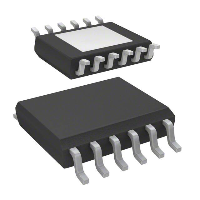
PowerSSO-24
– Reverse battery protected
– Electrostatic discharge protection
Applications
General
– Inrush current active management by
power limitation
– Very low standby current
– 3.0 V CMOS compatible inputs
– Optimized electromagnetic emissions
– Very low electromagnetic susceptibility
– Compliance with European directive
2002/95/EC
– Very low current sense leakage
Diagnostic functions
– Proportional load current sense
– High current sense precision for wide
currents range
– Current sense disable
– Off-state open load detection
– Output short to VCC detection
– Overload and short to ground (power
limitation) indication
– Thermal shutdown indication
Protections
– Undervoltage shutdown
– Overvoltage clamp
– Load current limitation
– Self limiting of fast thermal transients
– Protection against loss of ground and loss
of VCC
– Overtemperature shutdown with auto
restart (thermal shutdown)
September 2013
PowerSSO-12
■
All types of resistive, inductive and capacitive
loads
■
Suitable as LED driver
Description
The VND5E050ACJ-E and VND5E050ACK-E are
double channel high-side drivers manufactured
using ST proprietary VIPower® M0-5 technology
and housed in PowerSSO-12 and PowerSSO-24
packages. The devices are designed to drive 12 V
automotive grounded loads, and to provide
protection and diagnostics. They also implement
a 3 V and 5 V CMOS-compatible interface for use
with any microcontroller.
The devices integrate advanced protective
functions such as load current limitation, inrush
and overload active management by power
limitation, overtemperature shut-off with
auto-restart and overvoltage active clamp. A
dedicated analog current sense pin is associated
with every output channel providing enhanced
diagnostic functions including fast detection of
overload and short-circuit to ground through
power limitation indication, overtemperature
indication, short-circuit to VCC diagnosis on-state
and off-state open-load detection.
The current sensing and diagnostic feedback of
the whole device can be disabled by pulling the
CS_DIS pin high to share the external sense
resistor with similar devices.
Doc ID 022515 Rev 2
1/43
www.st.com
1
�Contents
VND5E050ACJ-E, VND5E050ACK-E
Contents
1
Block diagram and pin description . . . . . . . . . . . . . . . . . . . . . . . . . . . . . 6
2
Electrical specifications . . . . . . . . . . . . . . . . . . . . . . . . . . . . . . . . . . . . . . 8
3
2.1
Absolute maximum ratings . . . . . . . . . . . . . . . . . . . . . . . . . . . . . . . . . . . . . 8
2.2
Thermal data . . . . . . . . . . . . . . . . . . . . . . . . . . . . . . . . . . . . . . . . . . . . . . . 9
2.3
Electrical characteristics . . . . . . . . . . . . . . . . . . . . . . . . . . . . . . . . . . . . . . . 9
2.4
Waveforms . . . . . . . . . . . . . . . . . . . . . . . . . . . . . . . . . . . . . . . . . . . . . . . . 18
2.5
Electrical characteristics curves . . . . . . . . . . . . . . . . . . . . . . . . . . . . . . . . 21
Application information . . . . . . . . . . . . . . . . . . . . . . . . . . . . . . . . . . . . . 24
3.1
GND protection network against reverse battery . . . . . . . . . . . . . . . . . . . 24
3.1.1
Solution 1: resistor in the ground line (RGND only) . . . . . . . . . . . . . . . . 24
3.1.2
Solution 2: diode (DGND) in the ground line . . . . . . . . . . . . . . . . . . . . . 25
3.2
Load dump protection . . . . . . . . . . . . . . . . . . . . . . . . . . . . . . . . . . . . . . . . 25
3.3
MCU I/Os protection . . . . . . . . . . . . . . . . . . . . . . . . . . . . . . . . . . . . . . . . . 25
3.4
Current sense and diagnostic . . . . . . . . . . . . . . . . . . . . . . . . . . . . . . . . . . 25
3.4.1
3.5
4
5
Short to VCC and off-state open-load detection . . . . . . . . . . . . . . . . . . 26
Maximum demagnetization energy (VCC = 13.5V) . . . . . . . . . . . . . . . . . 28
Package and PCB thermal data . . . . . . . . . . . . . . . . . . . . . . . . . . . . . . . 29
4.1
PowerSSO-12 thermal data . . . . . . . . . . . . . . . . . . . . . . . . . . . . . . . . . . . 29
4.2
PowerSSO-24 thermal data . . . . . . . . . . . . . . . . . . . . . . . . . . . . . . . . . . . 31
Package and packing information . . . . . . . . . . . . . . . . . . . . . . . . . . . . . 35
5.1
ECOPACK® . . . . . . . . . . . . . . . . . . . . . . . . . . . . . . . . . . . . . . . . . . . . . . . 35
5.2
PowerSSO-12 package information . . . . . . . . . . . . . . . . . . . . . . . . . . . . . 35
5.3
PowerSSO-24 package information . . . . . . . . . . . . . . . . . . . . . . . . . . . . . 37
5.4
PowerSSO-12 packing information . . . . . . . . . . . . . . . . . . . . . . . . . . . . . 39
5.5
PowerSSO-24 packing information . . . . . . . . . . . . . . . . . . . . . . . . . . . . . 40
6
Order codes . . . . . . . . . . . . . . . . . . . . . . . . . . . . . . . . . . . . . . . . . . . . . . . 41
7
Revision history . . . . . . . . . . . . . . . . . . . . . . . . . . . . . . . . . . . . . . . . . . . 42
2/43
Doc ID 022515 Rev 2
�VND5E050ACJ-E, VND5E050ACK-E
List of tables
List of tables
Table 1.
Table 2.
Table 3.
Table 4.
Table 5.
Table 6.
Table 7.
Table 8.
Table 9.
Table 10.
Table 11.
Table 12.
Table 13.
Table 14.
Table 15.
Table 16.
Table 17.
Table 18.
Table 19.
Table 20.
Pin function . . . . . . . . . . . . . . . . . . . . . . . . . . . . . . . . . . . . . . . . . . . . . . . . . . . . . . . . . . . . . . 6
Suggested connections for unused and not connected pins . . . . . . . . . . . . . . . . . . . . . . . . 7
Absolute maximum ratings . . . . . . . . . . . . . . . . . . . . . . . . . . . . . . . . . . . . . . . . . . . . . . . . . . 8
Thermal data. . . . . . . . . . . . . . . . . . . . . . . . . . . . . . . . . . . . . . . . . . . . . . . . . . . . . . . . . . . . . 9
Power section . . . . . . . . . . . . . . . . . . . . . . . . . . . . . . . . . . . . . . . . . . . . . . . . . . . . . . . . . . . . 9
Switching (VCC = 13V; Tj = 25°C) . . . . . . . . . . . . . . . . . . . . . . . . . . . . . . . . . . . . . . . . . . . 10
Logic inputs. . . . . . . . . . . . . . . . . . . . . . . . . . . . . . . . . . . . . . . . . . . . . . . . . . . . . . . . . . . . . 10
Protections and diagnostics . . . . . . . . . . . . . . . . . . . . . . . . . . . . . . . . . . . . . . . . . . . . . . . . 11
Current sense (8 V < VCC < 18 V) . . . . . . . . . . . . . . . . . . . . . . . . . . . . . . . . . . . . . . . . . . . 11
Open load detection (8V
tDSTK(on)
VSENSE
VCS_DIS
Doc ID 022515 Rev 2
19/43
�Electrical specifications
VND5E050ACJ-E, VND5E050ACK-E
Figure 15. Short to VCC
Short to VCC
Resistive
Short to VCC
Hard
Short to VCC
VOUT > VOL
VOL
VOUT
IOUT
tDSTK(on)
tDSTK(on)
VCS_DIS
Figure 16. TJ evolution in overload or short to GND
TJ evolution in
Overload or Short to GND
INPUT
Self-limitation of fast thermal transients
TTSD
THYST
TR
TJ_START
TJ
ILimH >
Power Limitation
< ILimL
IOUT
20/43
Doc ID 022515 Rev 2
�VND5E050ACJ-E, VND5E050ACK-E
2.5
Electrical specifications
Electrical characteristics curves
Figure 17. Off-state output current
Figure 18. High level input current
Iloff (nA)
Iih (µA)
550
5
500
4,5
Vin=2.1V
Off State
Vcc=13V
Vin=Vout=0V
450
400
4
3,5
350
3
300
2,5
250
2
200
1,5
150
100
1
50
0,5
0
0
-50
-25
0
25
50
75
100
125
150
175
-50
-25
0
25
Tc (°C)
50
75
100
125
150
175
100
125
150
175
150
175
Tc (°C)
Figure 19. Input clamp voltage
Figure 20. Input low level
Vicl (V)
Vil (V)
7
2
6,8
1,8
lin=1mA
6,6
1,6
6,4
1,4
6,2
1,2
6
1
5,8
0,8
5,6
0,6
5,4
0,4
5,2
0,2
5
0
-50
-25
0
25
50
75
100
125
150
175
-50
-25
0
25
Tc (°C)
50
75
Tc (°C)
Figure 21. Input high level
Figure 22. Input hysteresis voltage
Vihyst (V)
Vih (V)
1
4
0,9
3,5
0,8
3
0,7
2,5
0,6
0,5
2
0,4
1,5
0,3
1
0,2
0,5
0,1
0
0
-50
-25
0
25
50
75
100
125
150
175
-50
-25
0
25
50
75
100
125
Tc (°C)
Tc (°C)
Doc ID 022515 Rev 2
21/43
�Electrical specifications
VND5E050ACJ-E, VND5E050ACK-E
Figure 23. On-state resistance vs Tcase
Figure 24. On-state resistance vs VCC
Ron (mOhm)
Ron (mOhm)
300
100
Iout= 2A
Vcc=13V
250
Tc=150°C
80
Tc=125°C
200
60
150
Tc=25°C
40
Tc=-40°C
100
20
50
0
0
-50
-25
0
25
50
75
100
125
150
0
175
5
10
15
20
25
30
35
40
Vcc (V)
Tc (°C)
Figure 25. Undervoltage shutdown
Figure 26. Turn-on voltage slope
Vusd (V)
(dVout/dt )On (V/ms)
16
1000
900
14
Vcc=13V
RI=6.5 Ohm
800
12
700
10
600
500
8
400
6
300
4
200
2
100
0
0
-50
-25
0
25
50
75
100
125
150
-50
175
-25
0
25
50
75
100
125
150
175
Tc (°C)
Tc (°C)
Figure 27. ILIMH vs Tcase
Figure 28. Turn-off voltage slope
Ilimh (A)
(dVout/dt )Off (V/ms)
40
600
550
35
500
Vcc=13V
Vcc=13V
RI= 6.5 Ohm
450
30
400
350
25
300
250
20
200
150
15
100
50
10
0
-50
-25
0
25
50
75
100
125
150
175
-50
Tc (°C)
22/43
-25
0
25
50
75
Tc (°C)
Doc ID 022515 Rev 2
100
125
150
175
�VND5E050ACJ-E, VND5E050ACK-E
Electrical specifications
Figure 29. CS_DIS high level voltage
Figure 30. CS_DIS clamp voltage
Vcsdh (V)
Vcsdcl(V)
4
10
3,5
9
8
Icsd = 1 mA
3
7
2,5
6
2
5
1,5
4
3
1
2
0,5
1
0
0
-50
-25
0
25
50
75
100
125
150
175
Tc (°C)
-50
-25
0
25
50
75
100
125
150
175
Tc (°C)
Figure 31. CS_DIS low level voltage
Vcsdl (V)
3
2,5
2
1,5
1
0,5
0
-50
-25
0
25
50
75
100
125
150
175
Tc (°C)
Doc ID 022515 Rev 2
23/43
�Application information
3
VND5E050ACJ-E, VND5E050ACK-E
Application information
Figure 32. Application schematic
+5V
VCC
Rprot
CS_DIS
Dld
ΜCU
Rprot
INPUT
OUTPUT
Rprot
CURRENT SENSE
GND
RSENSE
VGND
CEXT
RGND
DGND
Note:
Channel 2 has the same internal circuit as channel 1.
3.1
GND protection network against reverse battery
This section provides two solutions for implementing a ground protection network against
reverse battery.
3.1.1
Solution 1: resistor in the ground line (RGND only)
This can be used with any type of load.
The following is an indication on how to resize the RGND resistor.
1.
RGND ≤ 600 mV / (IS(on)max)
2.
RGND ≥ (−VCC) / (-IGND)
where -IGND is the DC reverse ground pin current and can be found in the absolute
maximum rating section of the device datasheet.
Power dissipation in RGND (when VCC < 0: during reverse battery situations) is:
PD = (-VCC)2/RGND
This resistor can be shared amongst several different HSDs. Please note that the value of
this resistor should be calculated with formula (1) where IS(on)max becomes the sum of the
maximum on-state currents of the different devices.
Please note that if the microprocessor ground is not shared by the device ground then the
RGND produces a shift (IS(on)max * RGND) in the input thresholds and the status output
values. This shift varies depending on how many devices are on in case of several high side
drivers sharing the same RGND.
24/43
Doc ID 022515 Rev 2
�VND5E050ACJ-E, VND5E050ACK-E
Application information
If the calculated power dissipation leads to a large resistor or several devices have to share
the same resistor then ST suggests to utilize Section 3.1.2: Solution 2: diode (DGND) in the
ground line.
3.1.2
Solution 2: diode (DGND) in the ground line
A resistor (RGND = 1 kΩ) should be inserted in parallel to DGND if the device drives an
inductive load.
This small signal diode can be safely shared amongst several different HSDs. Also in this
case, the presence of the ground network will produce a shift (≈600mV) in the input
threshold and in the status output values if the microprocessor ground is not common to the
device ground. This shift will not vary if more than one HSD shares the same diode/resistor
network.
3.2
Load dump protection
Dld is necessary (voltage transient suppressor) if the load dump peak voltage exceeds the
VCC maximum DC rating. The same applies if the device is subject to transients on the VCC
line that are greater than the ones shown in the ISO 7637-2: 2004(E) table.
3.3
MCU I/Os protection
If a ground protection network is used and negative transients are present on the VCC line,
the control pins are pulled negative.
ST suggests to insert a resistor (Rprot) in line to prevent the microcontroller I/O pins from
latching-up.
The value of these resistors is a compromise between the leakage current of microcontroller
and the current required by the HSD I/Os (Input levels compatibility) with the latch-up limit of
microcontroller I/Os:
-VCCpeak/Ilatchup ≤ Rprot ≤ (VOHμC-VIH-VGND) / IIHmax
Calculation example:
For VCCpeak = - 100V and Ilatchup ≥ 20mA; VOHµC ≥ 4.5V
5kΩ ≤ Rprot ≤ 180kΩ
Recommended values: Rprot =10kΩ, CEXT=10nF.
3.4
Current sense and diagnostic
The current sense pin performs a double function (see Figure 33: Current sense and
diagnostic):
●
Current mirror of the load current in normal operation, delivering a current
proportional to the load current according to a known ratio KX.
The current ISENSE can be easily converted to a voltage VSENSE by means of an
external resistor RSENSE. Linearity between IOUT and VSENSE is ensured up to 5V
minimum (see parameter VSENSE in Table 9: Current sense (8 V < VCC < 18 V)). The
current sense accuracy depends on the output current (refer to current sense electrical
Doc ID 022515 Rev 2
25/43
�Application information
VND5E050ACJ-E, VND5E050ACK-E
characteristics Table 9: Current sense (8 V < VCC < 18 V)).
●
Diagnostic flag in fault conditions, delivering a fixed voltage VSENSEH up to a
maximum current ISENSEH in case of the following fault conditions (refer to
Table 11: Truth table):
–
Power limitation activation
–
Overtemperature
–
Short to VCC in off-state
–
Open-load in off-state with additional external components.
A logic level high on the CS_DIS pin simultaneously sets all the current sense pins of the
device in a high impedance state, thus disabling the current monitoring and diagnostic
detection. This feature allows multiplexing of the microcontroller analog inputs by sharing
the sense resistance and ADC line among different devices.
Figure 33. Current sense and diagnostic
VPU
VBAT
VCC
Main MOSn
41V
PU_CMD
Overtemperature
IOUT/KX
RPU
+
OL OFF
ISENSEH
VOL
Pwr_Lim
CS_DIS
OUTn
ILoff2r
ILoff2f
INPUTn
VSENSEH
CURRENT
SENSEn
GND
RPROT
To uC ADC
3.4.1
RSENSE
Load
RPD
VSENSE
Short to VCC and off-state open-load detection
Short to VCC
A short circuit between VCC and output is indicated by the relevant current sense pin set to
VSENSEH during the device off-state. Little or no current is delivered by the current sense
during the on-state depending on the nature of the short circuit.
Off-state open-load with external circuitry
Detection of an open-load in off mode requires an external pull-up resistor (RPU) connecting
the output to a positive supply voltage (VPU).
26/43
Doc ID 022515 Rev 2
�VND5E050ACJ-E, VND5E050ACK-E
Application information
It is preferable that VPU is switched off during the module standby mode to avoid an increase
in overall standby current consumption in normal conditions, that is, when the load is
connected.
An external pull-down resistor (RPD) connected between output and GND is mandatory to
avoid misdetection in case of floating outputs in off-state (see Figure 33: Current sense and
diagnostic).
RPD must be selected in order to ensure VOUT < VOLmin unless pulled up by the external
circuitry:
VOUT
Pull − up _ OFF
= RPD ⋅ I L ( off 2 ) f < VOL min = 2V
RPD ≤ 22 KΩ is recommended.
For proper open load detection in off-state, the external pull-up resistor must be selected
according to the following formula:
VOUT
Pull − up _ ON
=
RPD ⋅ VPU − RPU ⋅ RPD ⋅ I L ( off 2) r
RPU + RPD
> VOL max = 4V
For the values of VOLmin,VOLmax, IL(off2)r and IL(off2)f see Table 10: Open load detection
(8V