VND7004AY
Double channel high-side driver with MultiSense analog
feedback for automotive applications
Datasheet - production data
Configurable latch-off on
overtemperature or power limitation
with dedicated fault reset pin
Loss of ground and loss of VCC
Reverse battery with self switch of the
PowerMOS
Electrostatic discharge protection
Applications
Features
Specially intended for Automotive smart power
distribution, glow plugs, heating systems, DC
motors, relay replacement and high power
resistive and inductive actuators.
Max transient supply voltage
VCC
40 V
Operating voltage range
VCC
4 to 28 V
Typ. on-state resistance (per Ch)
RON
4 mΩ
Description
Current limitation (typ)
ILIMH
100 A
Standby current (max)
ISTBY
0.5 µA
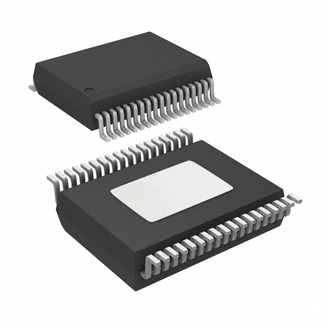
The device is a double channel high-side driver
manufactured using ST proprietary VIPower®
M0‑ 7 technology and housed in PowerSSO-36
package. The device is designed to drive 12 V
automotive grounded loads through a 3 V and
5 V CMOS-compatible interface, providing
protection and diagnostics.
AEC-Q100 qualified
General
Double channel smart high-side driver
with MultiSense analog feedback
Very low standby current
Compatible with 3 V and 5 V CMOS
outputs
MultiSense diagnostic functions
Multiplexed analog feedback of: load
current with high precision proportional
current mirror, VCC supply voltage and
TCHIP device temperature
Overload and short to ground (power
limitation) indication
Thermal shutdown indication
OFF-state open-load detection
Output short to VCC detection
Sense enable/disable
Protections
Undervoltage shutdown
Overvoltage clamp
Load current limitation
Self limiting of fast thermal transients
June 2017
The device integrates advanced protective
functions such as load current limitation, overload
active management by power limitation and
overtemperature shutdown with configurable
latch-off.
A FaultRST pin unlatches the output in case of
fault or disables the latch-off functionality.
A dedicated multifunction multiplexed analog
output pin delivers sophisticated diagnostic
functions including high precision proportional
load current sense, supply voltage feedback and
chip temperature sense, in addition to the
detection of overload and short circuit to ground,
short to VCC and OFF-state open-load.
A sense enable pin allows OFF-state diagnosis to
be disabled during the module low-power mode
as well as external sense resistor sharing among
similar devices.
DocID027772 Rev 11
This is information on a product in full production.
1/47
www.st.com
�Contents
VND7004AY
Contents
1
Block diagram and pin description ................................................ 5
2
Electrical specification .................................................................... 7
3
4
5
2.1
Absolute maximum ratings ................................................................ 7
2.2
Thermal data ..................................................................................... 8
2.3
Main electrical characteristics ........................................................... 8
2.4
Waveforms ...................................................................................... 20
2.5
Electrical characteristics curves ...................................................... 22
Protections..................................................................................... 26
3.1
Power limitation ............................................................................... 26
3.2
Thermal shutdown ........................................................................... 26
3.3
Current limitation ............................................................................. 26
3.4
Negative voltage clamp ................................................................... 26
Application information ................................................................ 27
4.1
GND protection network against reverse battery............................. 27
4.2
Immunity against transient electrical disturbances .......................... 28
4.3
MCU I/Os protection ........................................................................ 28
4.4
Multisense - analog current sense .................................................. 29
4.4.1
Principle of Multisense signal generation ......................................... 30
4.4.2
TCASE and VCC monitor ................................................................. 32
4.4.3
Short to VCC and OFF-state open-load detection ........................... 33
Package and PCB thermal data .................................................... 34
5.1
PowerSSO-36 thermal data ............................................................ 34
6
Maximum demagnetization energy (VCC = 16 V) ........................ 38
7
Package information ..................................................................... 39
8
9
2/47
7.1
PowerSSO-36 package information ................................................ 39
7.2
PowerSSO-36 packing information ................................................. 41
7.3
PowerSSO-36 marking information ................................................. 43
Order codes ................................................................................... 44
Revision history ............................................................................ 45
DocID027772 Rev 11
�VND7004AY
List of tables
List of tables
Table 1: Pin functions ................................................................................................................................. 5
Table 2: Suggested connections for unused and not connected pins ........................................................ 6
Table 3: Absolute maximum ratings ........................................................................................................... 7
Table 4: Thermal data ................................................................................................................................. 8
Table 5: Power section ............................................................................................................................... 8
Table 6: Switching..................................................................................................................................... 10
Table 7: Logic inputs ................................................................................................................................. 10
Table 8: Protections .................................................................................................................................. 11
Table 9: MultiSense .................................................................................................................................. 12
Table 10: Truth table ................................................................................................................................. 19
Table 11: MultiSense multiplexer addressing ........................................................................................... 19
Table 12: ISO 7637-2 - electrical transient conduction along supply line ................................................. 28
Table 13: MultiSense pin levels in off-state .............................................................................................. 32
Table 14: PCB properties ......................................................................................................................... 35
Table 15: Thermal parameters ................................................................................................................. 37
Table 16: PowerSSO-36 mechanical data................................................................................................ 39
Table 17: Reel dimensions ....................................................................................................................... 41
Table 18: PowerSSO-36 carrier tape dimensions .................................................................................... 42
Table 19: Device summary ....................................................................................................................... 44
Table 20: Document revision history ........................................................................................................ 45
DocID027772 Rev 11
3/47
�List of figures
VND7004AY
List of figures
Figure 1: Block diagram .............................................................................................................................. 5
Figure 2: Configuration diagram (top view)................................................................................................. 6
Figure 3: Current and voltage conventions ................................................................................................. 7
Figure 4: Switching time and Pulse skew ................................................................................................. 17
Figure 5: MultiSense timings (current sense mode) ................................................................................. 17
Figure 6: Multisense timings (chip temperature and VCC sense mode) .................................................. 18
Figure 7: TDSTKON.................................................................................................................................. 18
Figure 8: Latch functionality - behavior in hard short circuit condition (TAMB
很抱歉,暂时无法提供与“VND7004AYTR”相匹配的价格&库存,您可以联系我们找货
免费人工找货- 国内价格
- 1+65.76120
- 10+64.29240
- 30+63.32040
- 国内价格 香港价格
- 1+51.483241+6.62513
- 10+39.3472110+5.06341
- 25+36.3213325+4.67402
- 100+32.99580100+4.24607
- 250+31.67082250+4.07557
- 国内价格 香港价格
- 1000+29.667391000+3.81776
- 2000+29.019872000+3.73443
- 3000+28.695713000+3.69272