E M C
C o m p o n e n t s
July 2013
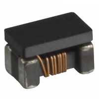
Common Mode Filters
For ultra high-speed differential signal line
(HDMI, DVI, DisplayPort, USB3.0, etc.)
ACM-D/-H series
ACM2012D
ACM2012H
[0805 inch]*
[0805 inch]
* Dimensions Code JIS[EIA]
�(2/9)
E M C
C o m p o n e n t s
REMINDERS FOR USING THESE PRODUCTS
Before using these products, be sure to request the delivery specifications.
SAFETY REMINDERS
Please pay sufficient attention to the warnings for safe designing when using these products.
REMINDERS
The storage period is less than 6 months. Be sure to follow the storage conditions (Temperature: 5 to 40°C, Humidity: 10 to 75% RH or
less).
If the storage period elapses, the soldering of the terminal electrodes may deteriorate.
Do not use or store in locations where there are conditions such as gas corrosion (salt, acid, alkali, etc.).
Before soldering, be sure to preheat components.
The preheating temperature should be set so that the temperature difference between the solder temperature and chip temperature
does not exceed 150°C.
Soldering corrections after mounting should be within the range of the conditions determined in the specifications.
If overheated, a short circuit, performance deterioration, or lifespan shortening may occur.
When embedding a printed circuit board where a chip is mounted to a set, be sure that residual stress is not given to the chip due to
the overall distortion of the printed circuit board and partial distortion such as at screw tightening portions.
Self heating (temperature increase) occurs when the power is turned ON, so the tolerance should be sufficient for the set thermal
design.
Carefully lay out the coil for the circuit board design of the non-magnetic shield type.
A malfunction may occur due to magnetic interference.
Use a wrist band to discharge static electricity in your body through the grounding wire.
Do not expose the products to magnets or magnetic fields.
Do not use for a purpose outside of the contents regulated in the delivery specifications.
The products listed on this catalog are intended for use in general electronic equipment (AV equipment, telecommunications
equipment, home appliances, amusement equipment, computer equipment, personal equipment, office equipment, measurement
equipment, industrial robots) under a normal operation and use condition.
The products are not designed or warranted to meet the requirements of the applications listed below, whose performance and/or
quality require a more stringent level of safety or reliability, or whose failure, malfunction or trouble could cause serious damage to
society, person or property.
If you intend to use the products in the applications listed below or if you have special requirements exceeding the range or conditions
set forth in the each catalog, please contact us.
(1) Aerospace/Aviation equipment
(2) Transportation equipment (cars, electric trains, ships, etc.)
(3) Medical equipment
(4) Power-generation control equipment
(5) Atomic energy-related equipment
(6) Seabed equipment
(7) Transportation control equipment
(8) Public information-processing equipment
(9) Military equipment
(10) Electric heating apparatus, burning equipment
(11) Disaster prevention/crime prevention equipment
(12) Safety equipment
(13) Other applications that are not considered general-purpose
applications
When designing your equipment even for general-purpose applications, you are kindly requested to take into consideration securing
protection circuit/device or providing backup circuits in your equipment.
001-01 / 20130723 / e9712_acm_dh.fm
�(3/9)
E M C
C o m p o n e n t s
Common Mode Filters
Product compatible with RoHS directive
Compatible with lead-free solders
For ultra high-speed differential signal line
(HDMI, DVI, DisplayPort, USB3.0, etc.)
Overview of the ACM-D/-H Series
FEATURES
Broadband common mode filter that was developed for Gbps-level high-speed differential signal interfaces such as DVI and HDMITM.
Differential mode cutoff frequency is 3.5GHz for ACM2012D and 6.0GHz for ACM2012H, so they do not negatively influence high-speed
differential signals.
Characteristics impedance is matched for 100:, which is set for many differential interfaces, and can suppress unnecessary reflection
components.
APPLICATION
EMI measure for HDMITM, which is an interface for digital video devices:
ACM2012H is ideal for senders (Sources) such as Digital TVs, DVD recorders, and liquid crystal projectors, while ACM2012D is ideal for
receivers (Sink).
EMI measure for high-speed differential signal interfaces for digital video signal interfaces such as DVI, Display port, and Serial ATA
used for PCs, etc.
PART NUMBER CONSTRUCTION
ACM
2012
-
Series
name
L×W×H Dimensions
(mm)
2.0×1.2×1.2
2012
2.0×1.2×1.3
D
-
Product
internal code
D
H
900
-
Impedance
(:)at 100MHz
900
90
2P
-
Number of lines
2P
2 lines
T
00
Packaging style
Internal code
T
TL
ø180mm reel
ø330mm reel
OPERATING TEMPERATURE RANGE, PACKAGE QUANTITY, PRODUCT WEIGHT
Type
Temperature range
Operating
Storage
temperature
temperature
(°C)
(°C)
ACM2012D
–40 to +85
–40 to +85
ACM2012H
–40 to +85
–40 to +85
Reel diameter
Package quantity
Individual weight
(mm)
ø180
ø330
ø180
ø330
(pieces/reel)
2,000
10,000
2,000
10,000
(mg)
10
10
�The Storage temperature range is for after the circuit board is mounted.
RoHS Directive Compliant Product: See the following for more details related to RoHS Directive compliant products. http://www.tdk.co.jp/rohs/
Halogen-free: Indicates that Cl content is less than 900ppm, Br content is less than 900ppm, and that the total Cl and Br content is less than 1500ppm.
• All specifications are subject to change without notice.
001-01 / 20130723 / e9712_acm_dh.fm
�(4/9)
E M C
C o m p o n e n t s
Overview of the ACM-D/-H Series
RECOMMENDED REFLOW PROFILE
Preheating
Soldering
Natural
cooling
Peak
T: Temperature
T4
T3
T2
T3
t3
T1
t1
t2
t: Time
Preheating
Temp.
T1
T2
150°C
180°C
Time
t1
60 to 120s
Soldering
Temp.
Time
T3
t2
230°C
10 to 30s
Peak
Temp.
T4
245°C
Time
t3
5s max.
• All specifications are subject to change without notice.
001-01 / 20130723 / e9712_acm_dh.fm
�(5/9)
E M C
C o m p o n e n t s
ACM-D/-H series
ACM2012D Type
SHAPE & DIMENSIONS
0.5
0.3
0.05
1.2±0.2
0.3
1.3max.
2.0±0.2
0.4
1.2
Dimensions in mm
0.4
0.4
1
4
2
3
0.4
0.75
1.1
0.75
CIRCUIT DIAGRAM
0.4
RECOMMENDED LAND PATTERN
• No polarity
Dimensions in mm
• All specifications are subject to change without notice.
001-01 / 20130723 / e9712_acm_dh.fm
�(6/9)
E M C
C o m p o n e n t s
ACM-D/-H series ACM2012D Type
ELECTRICAL CHARACTERISTICS
CHARACTERISTICS SPECIFICATION TABLE
Common mode
impedance
(: )
[at 100MHz]
min.
typ.
65
90
DC resistance
(: )max.
[1 line]
0.30
Insulation
Rated current Rated voltage
resistance
(mA)max.
(V)max.
(M: )min.
Cutoff
frequency
(GHz)typ.
Characteristic
impedance
(: )typ.
Part No.
300
3.5
100
ACM2012D-900-2P-T00
20
○ Measurement equipment
Measurement item
Product No.
Common mode impedance
4991A
DC resistance
4338A
Insulation resistance
4339A
* Equivalent measurement equipment may be used.
10
Manufacturer
Agilent Technologies
Agilent Technologies
Agilent Technologies
IMPEDANCE VS. FREQUENCY CHARACTERISTICS
10000
Impedance (Ω)
1000
100
900 Common mode
900 Differential mode
10
1
1
10
100
Frequency (MHz)
1000
10000
○ Measurement equipment
Product No.
Manufacturer
4991A
Agilent Technologies
* Equivalent measurement equipment may be used.
• All specifications are subject to change without notice.
001-01 / 20130723 / e9712_acm_dh.fm
�(7/9)
E M C
C o m p o n e n t s
ACM-D/-H series
ACM2012H Type
SHAPE & DIMENSIONS
0.35
0.5
1.2±0.2
0.35
0.4
1.2±0.1
2.0±0.2
0.4
1.2
Dimensions in mm
0.4
0.4
0.4
0.4
RECOMMENDED LAND PATTERN
0.75
1.1
0.75
CIRCUIT DIAGRAM
1
4
2
3
• No polarity
Dimensions in mm
• All specifications are subject to change without notice.
001-01 / 20130723 / e9712_acm_dh.fm
�(8/9)
E M C
C o m p o n e n t s
ACM-D/-H series ACM2012H Type
ELECTRICAL CHARACTERISTICS
CHARACTERISTICS SPECIFICATION TABLE
Common mode
impedance
(: )
[at 100MHz]
min.
typ.
65
90
DC resistance
(: )max.
[1 line]
Insulation
Rated current Rated voltage
resistance
(mA)max.
(V)max.
(M: )min.
Cutoff
frequency
(GHz)typ.
Characteristic
impedance
(: )typ.
Part No.
0.30
300
6
100
ACM2012H-900-2P-T00
20
○ Measurement equipment
Measurement item
Product No.
Common mode impedance
4991A
DC resistance
4338A
Insulation resistance
4339A
* Equivalent measurement equipment may be used.
10
Manufacturer
Agilent Technologies
Agilent Technologies
Agilent Technologies
IMPEDANCE VS. FREQUENCY CHARACTERISTICS
10000
Impedance (Ω)
1000
100
900 Common mode
900 Differential mode
10
1
1
10
100
Frequency (MHz)
1000
10000
○ Measurement equipment
Product No.
Manufacturer
4991A
Agilent Technologies
* Equivalent measurement equipment may be used.
• All specifications are subject to change without notice.
001-01 / 20130723 / e9712_acm_dh.fm
�(9/9)
E M C
C o m p o n e n t s
ACM-D/-H series
Packaging style
REEL DIMENSIONS
2.0±0.5
E
Type
ACM2012D
W1
9.5±0.5
9+1/–0
9.5±0.5
9+1/–0
W2
13.5±1
13±1
13.5±1
13±1
N
100±1
60+1/–0
100±1
60+1–0
E
2 typ.
2 typ.
2 typ.
2 typ.
N
ACM2012H
A
ø330±2
ø180±3
ø330±2
ø180±3
1.0
ø13.0±0.2
W1
ø21.0±0.8
W2
A
Dimensions in mm
TAPE DIMENSIONS
P2
P0
W
B
F
E
øD0
K
P1
A
Dimensions in mm
Type
ACM2012D
ACM2012H
A
1.4±0.1
1.4±0.1
B
2.25±0.1
2.25±0.1
øD0
1.5+0.1/0
1.5+0.1/0
E
1.75±0.1
1.75±0.1
F
3.5±0.1
3.5±0.1
P0
4.0±0.1
4.0±0.1
P1
4.0±0.1
4.0±0.1
P2
2.0±0.1
2.0±0.1
W
8.0±0.2
8.0±0.2
K
1.4±0.1
1.4±0.1
t
0.25±0.05
0.25±0.05
500 to 560min.
160min.
Taping
440min.
Drawing direction
Dimensions in mm
• All specifications are subject to change without notice.
001-01 / 20130723 / e9712_acm_dh.fm
�