R F
C o m p o n e n t s
September 2016
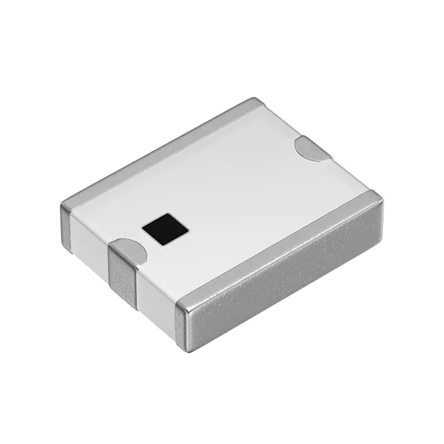
Multilayer Antenna (Triple Band type)
For 1574-1577MHz / 2400-2484MHz / 5150-5850MHz
ANT025020LCT1575MA1
2.5x2.0mm [EIA 1008]*
* Dimensions Code JIS[EIA]
Caution
The products in this catalog will be or have been
stopped production
Discontinue Issue Date
Apr. 28, 2021
Last Purchase Order Date
Dec. 31, 2022
Last Shipment Date
Mar. 31, 2023
Please refer to our Web site about replacement information.
�RF Components
Multilayer Antenna (Triple Band type)
Conformity to RoHS Directive
For 1574-1577MHz / 2400-2484MHz / 5150-5850MHz
pr
od
u
st cts
op w
pe il
d lb
pr e
od or
uc ha
tio ve
n
be
en
ANT025020LCT1575MA1
SHAPES AND DIMENSIONS
[Top view]
2.50±0.20
0.60±0.10
(1)
(3)
Terminal functions
1 Radiator electrode for GPS
2 Radiator electrode for 5.5GHz
3 Feed point
4 Radiator electrode for 2.4GHz
(0.21)
0.52±0.20
(0.21)
Marking
0.74±0.20
(2)
[Bottom view]
2.00±0.20
(4)
Dimensions in mm
2.00
Th
e
0.60
3.10
2.30
1.40
3.70
0.60
3.70
3.10
SOLDER RESIST PATTERN
1.40
RECOMMENDED LAND PATTERN
1.90
Dimensions in mm
1.90
Dimensions in mm
RoHS Directive Compliant Product: See the following for more details.https://product.tdk.com/info/en/environment/rohs/index.html
• All specifications are subject to change without notice.
• Before using these products, be sure to request the delivery specifications.
20160926 / rf_ant_ant025020lct1575ma1_summary
�RF Components
ANT025020LCT1575MA1
EVALUATION BOARD
pr
od
u
st cts
op w
pe il
d lb
pr e
od or
uc ha
tio ve
n
be
en
Mt Common
Ft 5.5GHz
ANT025020LCT1575MA1
Ft GPS
PCB size : 130mm x 75mm x 1mm
Antenna area : 16 x 6 mm
Ft 2.4GHz
Ft GPS
Ft 2.4GHz
Ft 5.5GHz
Mt Common
Component P/N
3.0nH
1.6pF
1.0nH
2.7nH
Measurement condition for Radiation Pattern
Z
Er
PCB
θ
Eø
Chip antenna
Eθ
Th
e
Y
ø
X
• All specifications are subject to change without notice.
• Before using these products, be sure to request the delivery specifications.
20160926 / rf_ant_ant025020lct1575ma1_summary
�RF Components
ANT025020LCT1575MA1
ELECTRICAL CHARACTERISTICS
VSWR
Frequency Range
(MHz)
Min.
Typ.
Max.
1574 to 1577
2400 to 2484
5150 to 5850
—
—
—
1.30
1.80
2.40
Linear
130 x 75
16 x 6
50 (Nominal)
4.0
4.0
4.0
pr
od
u
st cts
op w
pe il
d lb
pr e
od or
uc ha
tio ve
n
be
en
Item
Polarization
PCB size (mm)
Antenna keep-out area (mm)
Characteristic Impedance ()
・This is typical antenna performance with the standard PCB.
TEMPERATURE RANGE
Operating temperature
(°C)
–40 to +85
Storage temperature
(°C)
–40 to +85
FREQUENCY CHARACTERISTICS
Efficiency(dB)
–2
–3
–4
–5
–6
–7
–8
11
10
9
8
7
6
5
4
3
–9
2
–10
1
1.500 1.525 1.550 1.575 1.600 1.625 1.650
Frequency (GHz)
Efficiency
Spec (VSWR)
VSWR
2.4GHz BAND
5.5GHz BAND
0
11
10
–1
10
9
–2
9
8
–3
8
–4
7
–5
6
–6
5
4
–7
4
3
–8
3
–9
2
–10
1
2.300 2.350 2.400 2.450 2.500 2.550 2.600
Frequency (GHz)
–9
–10
2
1
–3
–4
–5
–6
–7
Th
e
–8
7
6
5
VSWR
Efficiency(dB)
–2
Efficiency(dB)
11
0
–1
Efficiency
Spec (VSWR)
VSWR
5
5.2
5.4
5.6
Frequency (GHz)
5.8
6
VSWR
0
–1
VSWR
GPS BAND
Efficiency
Spec (VSWR)
VSWR
• Tested antenna has been soldered. Evaluation board size is 130x75x1 mm.
• All specifications are subject to change without notice.
• Before using these products, be sure to request the delivery specifications.
20160926 / rf_ant_ant025020lct1575ma1_summary
�RF Components
ANT025020LCT1575MA1
GPS BAND
RHCP
Z-X plane
pr
od
u
st cts
op w
pe il
d lb
pr e
od or
uc ha
tio ve
n
be
en
RADIATION PATTERNS
Z-Y plane
X-Y plane
0°
10 (dBi)
315°
270°
225°
0
–10
–20
–30
–40
0°
10 (dBi)
315°
45°
90°
135°
Y
90°
0
–10
–20
–30
–40
270°
135°
225°
180°
Frequency(GHz)
Average(dBic)
Maximum(dBic)
Minimum(dBic)
315°
45°
0
–10
–20
–30
–40
270°
0°
10 (dBi)
Frequency(GHz)
Average(dBic)
Maximum(dBic)
Minimum(dBic)
90°
135°
225°
180°
1.5755
–6.4
–1.7
–19.6
45°
180°
Frequency(GHz)
Average(dBic)
Maximum(dBic)
Minimum(dBic)
1.5755
–6.5
–3.3
–13.4
1.5755
–4.8
–2.7
–8.8
Z
270°
90°
Y
270°
Z
90°
X
0°
X
0°
Z
90˚
Y
270˚
X
0˚
Th
e
• Tested antenna has been soldered. Evaluation board size is 130x75x1 mm.
• All specifications are subject to change without notice.
• Before using these products, be sure to request the delivery specifications.
20160926 / rf_ant_ant025020lct1575ma1_summary
�RF Components
ANT025020LCT1575MA1
RADIATION PATTERNS
pr
od
u
st cts
op w
pe il
d lb
pr e
od or
uc ha
tio ve
n
be
en
2.4GHz BAND
0°
10 (dBi)
315°
Y
270˚
270°
90˚
X
Z
0˚
0
–10
–20
–30
–40
0°
10 (dBi)
315°
45°
135°
225°
270°
90°
180°
Horizontal polarization
Frequency(GHz) 2.400 2.442
–6.7
–6.0
Average(dBi)
–1.7
–1.1
Maximum(dBi)
–23.6 –23.6
Minimum(dBi)
2.400GHz
2.442GHz
2.484GHz
2.484
–6.0
–1.0
–24.1
270°
270°
0
–10
–20
–30
–40
45°
90°
135°
225°
180°
Vertical polarization
Frequency(GHz) 2.400 2.442
–10.8 –10.4
Average(dBi)
–7.3
–6.7
Maximum(dBi)
–21.7 –20.3
Minimum(dBi)
0°
10 (dBi)
315°
0
–10
–20
–30
–40
2.400GHz
2.442GHz
2.484GHz
2.484
–10.7
–6.8
–20.8
0°
10 (dBi)
315°
45°
270°
90°
0
–10
–20
–30
40
45°
90°
90°
Y
0°
Z
X
135°
225°
180°
Horizontal polarization
Frequency(GHz) 2.400 2.442
–5.4
–4.8
Average(dBi)
–0.7
0.2
Maximum(dBi)
–25.3 –21.5
Minimum(dBi)
2.400GHz
2.442GHz
2.484GHz
2.484
–4.9
0.4
–24.3
180°
Vertical polarization
Frequency(GHz) 2.400 2.442
–21.1 –19.8
Average(dBi)
–13.9 –12.1
Maximum(dBi)
–44.8 –45.8
Minimum(dBi)
0°
10 (dBi)
315°
Z
90˚
Y
270˚
X
270°
0˚
225°
0
–10
–20
–30
40
135°
225°
2.400GHz
2.442GHz
2.484GHz
2.484
–19.9
–12.3
–62.6
0°
10 (dBi)
315°
45°
270°
90°
135°
2.484
–11.0
–5.4
–62.6
225°
45°
90°
135°
180°
Vertical polarization
Frequency(GHz) 2.400 2.442
–2.8
–2.3
Average(dBi)
–0.8
–0.2
Maximum(dBi)
–5.0
–4.2
Minimum(dBi)
2.400GHz
2.442GHz
2.484GHz
2.484
–2.5
–0.3
–4.3
Th
e
180°
Horizontal polarization
Frequency(GHz) 2.400 2.442
–10.5 –10.2
Average(dBi)
–4.9
–4.6
Maximum(dBi)
–38.2 –40.7
Minimum(dBi)
2.400GHz
2.442GHz
2.484GHz
0
–10
–20
–30
–40
• Tested antenna has been soldered. Evaluation board size is 130x75x1 mm.
• All specifications are subject to change without notice.
• Before using these products, be sure to request the delivery specifications.
20160926 / rf_ant_ant025020lct1575ma1_summary
�RF Components
ANT025020LCT1575MA1
RADIATION PATTERNS
pr
od
u
st cts
op w
pe il
d lb
pr e
od or
uc ha
tio ve
n
be
en
5.5GHz BAND
0°
10 (dBi)
315°
Y
270˚
270°
90˚
X
Z
0˚
0
–10
–20
–30
–40
0°
10 (dBi)
315°
45°
135°
225°
270°
90°
180°
Horizontal polarization
Frequency(GHz) 5.150 5.500
–16.4 –12.4
Average(dBi)
–7.5
–7.1
Maximum(dBi)
–40.0 –38.7
Minimum(dBi)
5.150GHz
5.500GHz
5.850GHz
5.850
–8.6
–3.8
–33.9
270°
270°
0
–10
–20
–30
–40
45°
90°
135°
225°
180°
Vertical polarization
Frequency(GHz) 5.150 5.500
–4.4
–3.3
Average(dBi)
–1.5
–0.5
Maximum(dBi)
–19.1 –20.7
Minimum(dBi)
0°
10 (dBi)
315°
0
–10
–20
–30
–40
5.150GHz
5.500GHz
5.850GHz
5.850
–5.0
–1.7
–27.1
0°
10 (dBi)
315°
45°
270°
90°
0
–10
–20
–30
–40
45°
90°
90°
Y
0°
Z
X
135°
225°
180°
Horizontal polarization
Frequency(GHz) 5.150 5.500
–3.3
–3.5
Average(dBi)
3.3
2.8
Maximum(dBi)
–15.7 –20.6
Minimum(dBi)
5.150GHz
5.500GHz
5.850GHz
5.850
–3.6
1.5
–35.9
180°
Vertical polarization
Frequency(GHz) 5.150 5.500
–18.8 –14.8
Average(dBi)
–11.3
–7.4
Maximum(dBi)
–40.0 –36.2
Minimum(dBi)
0°
10 (dBi)
315°
Z
90˚
Y
270˚
X
270°
0˚
225°
0
–10
–20
–30
–40
135°
225°
5.150GHz
5.500GHz
5.850GHz
5.850
–15.6
–9.6
–38.6
0°
10 (dBi)
315°
45°
270°
90°
135°
5.850
–4.0
2.4
–28.1
225°
45°
90°
135°
180°
Vertical polarization
Frequency(GHz) 5.150 5.500
–5.1
–6.0
Average(dBi)
1.0
1.2
Maximum(dBi)
–34.5 –21.4
Minimum(dBi)
5.150GHz
5.500GHz
5.850GHz
5.850
–4.3
0.1
–11.0
Th
e
180°
Horizontal polarization
Frequency(GHz) 5.150 5.500
–2.5
–2.2
Average(dBi)
4.1
4.0
Maximum(dBi)
–26.9 –27.2
Minimum(dBi)
5.150GHz
5.500GHz
5.850GHz
0
–10
–20
–30
–40
• Tested antenna has been soldered. Evaluation board size is 130x75x1 mm.
• All specifications are subject to change without notice.
• Before using these products, be sure to request the delivery specifications.
20160926 / rf_ant_ant025020lct1575ma1_summary
�RF Components
pr
od
u
st cts
op w
pe il
d lb
pr e
od or
uc ha
tio ve
n
be
en
RECOMMENDED REFLOW PROFILE
Preheating
Soldering
Peak
T4
T: Temperature
3°C/sec
or lower
6°C/sec
or lower
T3
T2
T1
t1
T3
t3
t2
t: Time
Preheating
Temp.
T1
150°C
t3
T2
200°C
Time
t1
60 to 120sec
Soldering
Critical zone (T3 to T4)
Temp.
Time
T3
t2
217°C
60 to 120sec
Th
e
: Time within 5°C of actual peak temperature
The maximum number of reflow is 3.
• All specifications are subject to change without notice.
• Before using these products, be sure to request the delivery specifications.
Peak
Temp.
T4
240 to 260°C
Time
t3
30sec max.
�RF Components
ANT025020LCT1575MA1
PACKAGING STYLE
pr
od
u
st cts
op w
pe il
d lb
pr e
od or
uc ha
tio ve
n
be
en
REEL DIMENSIONS
ø60–0.0
+1.0
2.0±0.5
9.0 +1.0
–0.0
ø13±0.2
ø21±0.8
13.0±1.0
+0
ø180 –1.5
Dimensions in mm
0.25±0.05
B
3.5±0.05
4.0±0.1
A
8.0±0.2
2.0±0.05
ø1.5 +0.1
0
1.75±0.1
TAPE DIMENSIONS
4.0±0.1
K
Dimensions in mm
A
2.35±0.05
B
2.85±0.05
K
0.90±0.05
PACKAGE QUANTITY
Th
e
Standard package quantity
(pieces/reel)
2,000
• All specifications are subject to change without notice.
• Before using these products, be sure to request the delivery specifications.
20160926 / rf_ant_ant025020lct1575ma1_summary
�RF Components
REMINDERS FOR USING THESE PRODUCTS
Before using these products, be sure to request the delivery specifications.
pr
od
u
st cts
op w
pe il
d lb
pr e
od or
uc ha
tio ve
n
be
en
SAFETY REMINDERS
Please pay sufficient attention to the warnings for safe designing when using these products.
REMINDERS
The products listed on this catalog are intended for use in general electronic equipment (AV equipment, telecommunications equipment,
home appliances, amusement equipment, computer equipment, personal equipment, office equipment, measurement equipment,
industrial robots) under a normal operation and use condition.
The products are not designed or warranted to meet the requirements of the applications listed below, whose performance and/or quality
require a more stringent level of safety or reliability, or whose failure, malfunction or trouble could cause serious damage to society, person
or property.
Please understand that we are not responsible for any damage or liability caused by use of the products in any of the applications below
or for any other use exceeding the range or conditions set forth in this catalog.
(1) Aerospace/Aviation equipment
(2) Transportation equipment (cars, electric trains, ships, etc.)
(3) Medical equipment
(4) Power-generation control equipment
(5) Atomic energy-related equipment
(6) Seabed equipment
(7) Transportation control equipment
(8) Public information-processing equipment
(9) Military equipment
(10) Electric heating apparatus, burning equipment
(11) Disaster prevention/crime prevention equipment
(12) Safety equipment
(13) Other applications that are not considered general-purpose
applications
Th
e
When using this product in general-purpose applications, you are kindly requested to take into consideration securing protection circuit/
equipment or providing backup circuits, etc., to ensure higher safety.
• All specifications are subject to change without notice.
• Before using these products, be sure to request the delivery specifications.
20160926 / rf_ant_ant025020lct1575ma1_summary
�
ANT025020LCT1575MA1 价格&库存
很抱歉,暂时无法提供与“ANT025020LCT1575MA1”相匹配的价格&库存,您可以联系我们找货
免费人工找货- 国内价格 香港价格
- 1+6.639791+0.82352
- 10+5.8305710+0.72315
- 25+5.4753425+0.67910
- 100+4.46733100+0.55408
- 250+4.14937250+0.51464
- 500+3.53125500+0.43798
- 1000+2.824991000+0.35038


 工商网监
湘ICP备2023018690号
工商网监
湘ICP备2023018690号
