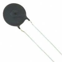
NTC thermistors for
inrush current limiting
Leaded and coated disks
Series/Type:
B57237S0***M0**
Date:
November 2015
© EPCOS AG 2015. Reproduction, publication and dissemination of this publication, enclosures hereto and the
information contained therein without EPCOS' prior express consent is prohibited.
EPCOS AG is a TDK Group Company.
�Inrush current limiters
B57237S0***M0**
ICLs
S237
Applications
Inrush current limiting, e.g. in switch-mode power
supplies, soft-start motors
Dimensional drawing
Features
Leaded and coated NTC thermistors
Tinned copper wire, kinked
Coating material flame retardant to UL 94 V-0
Component marking includes the manufacturer's
logo, resistance value and date code
Highly stable electrical characteristics
Approvals
UL 1434 (file number E69802)
IEC (certificate number 101QA12)
VDE (certificate number 40038223)
CQC (0900104539)
Dimensions in mm
Approx. weight 2 g
Options
Resistance tolerance 25 °C
Tmax = 170 °C
Derating curve for types S153, S235, S236, S238, S364 and S464
Figure 2
Please read Cautions and warnings and
Important notes at the end of this document.
Page 8 of 21
�Inrush current limiters
B57237S0***M0**
ICLs
S237
TA = Ambient temperature > 65 °C
Tmax = 170 °C
The Imax values specified in the data sheets denote the maximum permissible continuous current
(DC or RMS values for sine-shaped AC) in the temperature range 0 °C to 65 °C.
1.6 Maximum permissible capacitance
The currents during turn-on are much higher than the rated currents during continuous operation.
To test the effects of these current surges EPCOS uses the following standard procedure according to IEC 60539-1:
Figure 3
Test circuit for evaluating the maximum permissible capacitance of an NTC thermistor
Vload
Load voltage [V]
Ctest
Test capacitance [µF]
RS
Series resistance [RS = 1 Ω]
VNTC
Voltage drop across the NTC under test [V]
The capacitor Ctest is discharged via the series resistor RS and the NTC inrush current limiter. The
load voltage is chosen such that the voltage applied to the thermistor at the start of discharge is
VNTC = 375 V (corresponds to (230 V + ∆V) � �2).
Please read Cautions and warnings and
Important notes at the end of this document.
Page 9 of 21
�Inrush current limiters
B57237S0***M0**
ICLs
S237
Figure 4
Maximum permissible capacitance discharging test: typical curves
The maximum capacitances that can be switched depend on the individual thermistor type and
are given in the data sheets.
Please read Cautions and warnings and
Important notes at the end of this document.
Page 10 of 21
�Inrush current limiters
B57237S0***M0**
ICLs
S237
Taping and packing
1
Taping of radial leaded ICL NTC thermistors according to the
specified lead spacing
Dimensions and tolerances
Lead spacing F = 5.0 mm (taping to IEC 60286-2)
for the following types: S153, S235 and S236
Lead spacing F = 7.5 mm (taping based on IEC 60286-2)
for the following types: P11, P13, S237, S238 and S364
Please read Cautions and warnings and
Important notes at the end of this document.
Page 11 of 21
�Inrush current limiters
B57237S0***M0**
ICLs
S237
Dimensions (mm)
Lead
spacing
5 mm
Tolerance of
lead spacing
5 mm
Lead
spacing
7.5 mm
Tolerance of
lead spacing
7.5 mm
≥12.0
Remarks
w
≤12.0
th
6.0
max.
7
max.
please refer to dimensional
drawings
d
0.5/0.6
±0.05
0.8/1.0
±0.05
please refer to dimensional
drawings
P0
12.7
±0.3
12.7
±0.3
±1 mm / 20 sprocket holes
P1
3.85
±0.7
8.95
±0.8
F
5.0
+0.6/�0.1
7.5
±0.8
∆h
0
±2.0
0
∆p
0
±1.3
0
±2.0
W
18.0
±0.5
18.0
±0.5
W0
5.5
min.
11.0
min.
W1
9.0
+0.75/�0.5
9.0
+0.75/�0.5
please refer to dimensional
drawings
Depends on th measured at top
of component body
W2
3.0
max.
3.0
max.
H
18.0
+2.0/�0
18.0
+2.0/�0
H0
16.0
±0.5
16.0
±0.5
H1
32.2
max.
45.0
max.
D0
4.0
±0.2
4.0
±0.2
t
0.9
max.
0.9
max.
L
11.0
max.
11.0
max.
L1
4.0
max.
4.0
max.
Please read Cautions and warnings and
Important notes at the end of this document.
Page 12 of 21
peel-off force ≥5 N
applies only to uncrimped
types
applies only to crimped types
without wires
�Inrush current limiters
B57237S0***M0**
ICLs
S237
Types of packing
Reel packing
Reel dimensions (in mm)
Reel type
Series
pcs. per reel d
f
n
w
I
S153, S235
1500
360 max.
31 ±1
approx. 45
54 max.
I
S236
1000
360 max.
31 ±1
approx. 45
54 max.
II
P11, P13
1500
500 max.
23 ±1
approx. 59
72 max.
II
S237, S238, S364
1000
500 max.
23 ±1
approx. 59
72 max.
Ammo packing
Ammo Series
type
pcs. per x
package
y
z
I
S153,
S235,
S236
1000
45
335
272
II
P11,
P13,
S237,
S238,
S364
750
55
340
340
Ammo packing dimensions (in mm)
Bulk packing
The components are packed in cardboard boxes, the size of which depends on the order quantity.
Series S464 and P27 is only available as bulk.
Please read Cautions and warnings and
Important notes at the end of this document.
Page 13 of 21
�Inrush current limiters
B57237S0***M0**
ICLs
S237
Mounting instructions
1
Soldering
1.1
Leaded NTC thermistors
Leaded thermistors comply with the solderability requirements specified by CECC.
When soldering, care must be taken that the NTC thermistors are not damaged by excessive
heat. The following maximum temperatures, maximum time spans and minimum distances have
to be observed:
Dip soldering
Iron soldering
Bath temperature
max. 260 °C
max. 360 °C
Soldering time
max. 4 s
max. 2 s
Distance from thermistor
min. 6 mm
min. 6 mm
Under more severe soldering conditions the resistance may change.
Solderability (test to IEC 60068-2-20)
Preconditioning: Immersion into flux F-SW 32.
Evaluation criterion: Wetting of soldering areas ≥95%.
Solder
Bath temperature (°C)
Dwell time (s)
SnAg (3.0 ... 4.0), Cu (0.5 ... 0.9)
245 ±3
3
1.1.1
Resistance to soldering heat (test to IEC 60068-2-20)
Preconditioning: Immersion into flux F-SW 32.
Solder
Bath temperature (°C)
Dwell time (s)
SnAg (3.0 ... 4.0), Cu (0.5 ... 0.9)
260 �5
10
Please read Cautions and warnings and
Important notes at the end of this document.
Page 14 of 21
�Inrush current limiters
B57237S0***M0**
ICLs
1.1.2
S237
Wave soldering
Temperature characteristic at component terminal with dual wave soldering
2
Robustness of terminations
The leads meet the requirements of IEC 60068-2-21. They may not be bent closer than 4 mm
from the solder joint on the thermistor body or from the point at which they leave the feedthroughs. During bending, any mechanical stress at the outlet of the leads must be removed. The
bending radius should be at least 0.75 mm.
Tensile strength:
Test Ua1:
Leads
0.50 < ∅ ≤0.80 mm = 10.0 N
0.80 < ∅ ≤1.25 mm = 20.0 N
Bending strength: Test Ub:
Two 90°-bends in opposite directions at a weight of 0.25 kg.
Torsional strength: Test Uc: severity 2
The lead is bent by 90° at a distance of 6 to 6.5 mm from the thermistor body.
The bending radius of the leads should be approx. 0.75 mm. Two torsions of
180° each (severity 2).
Please read Cautions and warnings and
Important notes at the end of this document.
Page 15 of 21
�Inrush current limiters
B57237S0***M0**
ICLs
S237
When subjecting leads to mechanical stress, the following should be observed:
Tensile stress on leads
During mounting and operation tensile forces on the leads are to be avoided.
Bending of leads
Bending of the leads directly on the thermistor body is not permissible.
A lead may be bent at a minimum distance of twice the wire's diameter +2 mm from the solder
joint on the thermistor body. During bending the wire must be mechanically relieved at its outlet.
The bending radius should be at least 0.75 mm.
Twisting of leads
The twisting (torsion) by 180° of a lead bent by 90° is permissible at 6 mm from the bottom of the
thermistor body.
3
Sealing and potting
When thermistors are sealed, potted or overmolded, there must be no mechanical stress caused
by thermal expansion during the production process (curing / overmolding process) and during
later operation. The upper category temperature of the thermistor must not be exceeded. Ensure
that the materials used (sealing / potting compound and plastic material) are chemically neutral.
4
Cleaning
If cleaning is necessary, mild cleaning agents such as ethyl alcohol and cleaning gasoline are
recommended. Cleaning agents based on water are not allowed. Ultrasonic cleaning methods are
permissible.
5
Storage
In order to maintain their solderability, thermistors must be stored in a non-corrosive atmosphere.
Humidity, temperature and container materials are critical factors.
The components should be left in the original packing. Touching the metallization of unsoldered
thermistors may change their soldering properties.
�25 °C up to 45 °C
Storage temperature:
Max. relative humidity (without condensation):
很抱歉,暂时无法提供与“B57237S0109M000”相匹配的价格&库存,您可以联系我们找货
免费人工找货- 国内价格
- 1+1.84800
- 50+1.43000
- 500+1.32000
- 国内价格 香港价格
- 1+13.419841+1.73586
- 5+11.107405+1.43675
- 10+10.2501110+1.32586
- 50+8.5077850+1.10048
- 100+7.85002100+1.01540
- 250+7.05480250+0.91254
- 国内价格
- 1+2.91600
- 10+2.32200
- 30+2.07360
- 100+1.74960
- 500+1.60920
- 1000+1.53360
- 国内价格
- 250+8.09156
- 500+7.91452