NTC thermistors for
temperature measurement
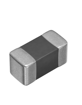
SMD NTC thermistors,
case size 0603 (1608), automotive series
Series/Type:
B573**V5
Date:
June 2012
© EPCOS AG 2012. Reproduction, publication and dissemination of this publication, enclosures hereto and the
information contained therein without EPCOS' prior express consent is prohibited.
�Temperature measurement and compensation
B573**V5
SMD NTC thermistors, case size 0603 (1608)
Applications
Temperature measurement and compensation
Automotive series
Dimensional drawing
Features
Qualification based on AEC-Q200 Rev-D
Multilayer SMD NTC with inner electrodes
Nickel barrier termination
For temperature measurement up to 150 °C
Excellent long-term aging stability in high
temperature and high humidity environment
Options
Alternative resistance ratings, resistance
tolerances and B value tolerances available on
request.
Delivery mode
Cardboard tape, 180-mm reel
Dimensions in mm
Approx. weight 6 mg
General technical data
Operating temperature range
Max. power
Resistance tolerance
Rated temperature
Dissipation factor
Thermal cooling time constant
Heat capacity
Top
(at 25 °C, on PCB) P251)
∆RR/RR
TR
(on PCB)
δth1)
(on PCB)
τc1)
Cth1)
1) Depends on mounting situation
Please read Cautions and warnings and
Important notes at the end of this document.
Page 2 of 24
�40 ... 150
180
±1, ±3, ±5
25
approx. 3
approx. 4
approx. 12
°C
mW
%
°C
mW/K
s
mJ/K
�Temperature measurement and compensation
B573**V5
SMD NTC thermistors, case size 0603 (1608)
Automotive series
Electrical specification and ordering codes
R25
Ω
10 k
10 k
10 k
10 k
10 k
22 k
22 k
47 k
100 k
100 k
100 k
No. of R/T
characteristic
8500
8502
8507
8509
8509
8502
8507
8507
8507
8507
8507
B25/50
K
3590
3940
4386
3380
3380
3940
4386
4386
4386
4386
4386
B25/85
K
3635
3980
4455
3435
3435
3980
4455
4455
4455
4455
4455
B25/100
K
3650 ±3%
4000 ±3%
4480 ±3%
3455 ±1%
3455 ±1%
4000 ±3%
4480 ±3%
4480 ±3%
4480 ±1%
4480 ±1%
4480 ±3%
+ = Resistance tolerance
F = ±1% (only for type B57332V5103F360 and B57352V5104F360)
H = ±3%
J = ±5%
Please read Cautions and warnings and
Important notes at the end of this document.
Page 3 of 24
Ordering code
B57342V5103+060
B57351V5103+060
B57352V5103+060
B57332V5103+360
B57332V5103F360
B57351V5223+060
B57352V5223+060
B57352V5473+060
B57352V5104+360
B57352V5104F360
B57352V5104+060
�Temperature measurement and compensation
SMD NTC thermistors, case size 0603 (1608)
B573**V5
Automotive series
Reliability data only for type B57332V5103F360
Tests of SMD NTC thermistors are based on AEC-Q200 Rev-D. The parts are mounted on
standardized PCB.
Test
Pre- and
post-stress
electrical test
High temperature
exposure
(storage)
Temperature
cycling
Standard
Test conditions
∆R25/R25 Remarks
(typical)
Resistance at: 25 °C and 100 °C
Test temperature: 150 °C
Duration: 1000 h
Unpowered
JESD22,
Lower test temperature: �40 °C
method JA-104 Upper test temperature: 150 °C
Number of cycles: 1000
Transfer time: < 10 s
Dwell time: 15 min
Air � Air
< 1%
< 3%
Physical
dimensions
Test temperature: 85 °C
Rel. humidity of air: 85%
Duration: 1000 h
Test voltage: VNTC = 0.3 V DC
MIL-STD-202, Test temperature: 150 °C
method 108
Pmax = 0.35 mW
Duration: 1000 h
MIL-STD-883E, Visual inspection
method 2009
JESD22,
Measured with calibers
method JB-100
Resistance to
solvents
MIL-STD-202,
method 215
Mechanical shock
MIL-STD-202,
method 213
Biased humidity
Operational life
External visual
MIL-STD-202,
method 108
MIL-STD-202,
method 103
Please read Cautions and warnings and
Important notes at the end of this document.
< 3%
< 3%
Not applicable for SMD thermistors
(component has no marking, color
coding or coating)
Peak value: 1500 g
< 1%
Half sine
Condition F
Page 4 of 24
Temperature
cycling is
performed
acc.
MIL-STD-202,
method 107.
No warrant
will be
assumed for
the reliability
of solder
joint.
Within the
specified
values
�Temperature measurement and compensation
SMD NTC thermistors, case size 0603 (1608)
Test
Standard
Vibration
MIL-STD-202,
method 204
Resistance to
soldering heat
ESD
Solderability
Electrical
characterization
Flammability
Board flex
Terminal strength
Resistance drift
after soldering
Test conditions
Acceleration: 5 g
Sweep time: 20 min
Frequency range: 10 ... 2000 Hz
3 × 12 cycles
MIL-STD-202, Dip: 260 °C; 10 s
method 210
1 heat cycle
AEC-Q200-002, Discharge capacitance: 150 pF
method -002
Discharge resistance: 2 kΩ
Charging voltage: 6 kV
Contact discharge
2 pulses in each polarity
J-STD-002
a) Dip: 235 °C; 5 s:
aging 4 h @ 155 °C
b) Dip: 215 °C; 5 s:
steam aging 8 h @ 92 °C
c) Dip: 260 °C; 7 s:
steam aging 8 h @ 92 °C
R(25 °C), R(100 °C), B(25/100)
UL-94,
V-0 or V-1
B573**V5
Automotive series
∆R25/R25 Remarks
(typical)
< 1%
< 1%
< 3%
Not applicable for SMD thermistors
(component is not coated or
encapsulated with plastic
materials)
AEC-Q200-005, Max. bending: 2 mm
< 2%
method -005
Duration @ max. bending: 60 s
AEC-Q200-006, Max. F: 10 N
< 2%
method -006
Reflow soldering profile
< 1%
Wave soldering profile
Please read Cautions and warnings and
Important notes at the end of this document.
Page 5 of 24
95% of
termination
wetted
Within the
specified
values
�Temperature measurement and compensation
SMD NTC thermistors, case size 0603 (1608)
B573**V5
Automotive series
Reliability data
Tests of SMD NTC thermistors are based on AEC-Q200 Rev-D. The parts are mounted on
standardized PCB.
Test
Pre- and
post-stress
electrical test
High temperature
exposure
(storage)
Temperature
cycling
Standard
Test conditions
Resistance at: 25 °C and 100 °C
Physical
dimensions
Test temperature: 150 °C
Duration: 1000 h
Unpowered
JESD22,
Lower test temperature: �40 °C
method JA-104 Upper test temperature: 150 °C
Number of cycles: 1000
Transfer time: < 10 s
Dwell time: 15 min
Air � Air
MIL-STD-202, Test temperature: 85 °C
method 103
Rel. humidity of air: 85%
Duration: 1000 h
Test voltage: VNTC = 0.3 V DC
MIL-STD-202, Test temperature: 150 °C
method 108
Pmax = 0.35 mW
Duration: 1000 h
MIL-STD-883E, Visual inspection
method 2009
JESD22,
Measured with calibers
method JB-100
Resistance to
solvents
MIL-STD-202,
method 215
Mechanical shock
MIL-STD-202,
method 213
Vibration
MIL-STD-202,
method 204
Resistance to
soldering heat
MIL-STD-202,
method 210
Biased humidity
Operational life
External visual
∆R25/R25 Remarks
(typical)
MIL-STD-202,
method 108
Please read Cautions and warnings and
Important notes at the end of this document.
< 5%
< 5%
< 5%
< 5%
Not applicable for SMD thermistors
(component has no marking, color
coding or coating)
Peak value: 1500 g
< 5%
Half sine
Condition F
Acceleration: 5 g
< 5%
Sweep time: 20 min
Frequency range: 10 ... 2000 Hz
3 × 12 cycles
Dip: 260 °C; 10 s
< 3%
1 heat cycle
Page 6 of 24
Within the
specified
values
�Temperature measurement and compensation
SMD NTC thermistors, case size 0603 (1608)
Test
Standard
ESD
AEC-Q200-002, Discharge capacitance: 150 pF
method -002
Discharge resistance: 2 kΩ
Charging voltage: 6 kV
Contact discharge
2 pulses in each polarity
J-STD-002
a) Dip: 235 °C; 5 s:
aging 4 h @ 155 °C
b) Dip: 215 °C; 5 s:
steam aging 8 h @ 92 °C
c) Dip: 260 °C; 7 s:
steam aging 8 h @ 92 °C
R(25 °C), R(100 °C), B(25/100)
Solderability
Electrical
characterization
Flammability
Board flex
Terminal strength
Resistance drift
after soldering
Test conditions
UL-94
V-0 or V-1
B573**V5
Automotive series
∆R25/R25 Remarks
(typical)
< 5%
Not applicable for SMD thermistors
(component is not coated or
encapsulated with plastic
materials)
AEC-Q200-005, Max. bending: 2 mm
< 5%
method -005
Duration @ max. bending: 60 s
AEC-Q200-006, Max. F: 10 N
< 5%
method -006
Reflow soldering profile
< 1%
Wave soldering profile
Please read Cautions and warnings and
Important notes at the end of this document.
Page 7 of 24
95% of
termination
wetted
Within the
specified
values
�Temperature measurement and compensation
B573**V5
SMD NTC thermistors, case size 0603 (1608)
Automotive series
R/T characteristics
R/T No.
T (°C)
8500
8502
8507
B25/100 = 3650 K
B25/100 = 4000 K
B25/100 = 4480 K
RT/R25
α (%/K) RT/R25
α (%/K) RT/R25
α (%/K)
�55.0
�50.0
�45.0
�40.0
�35.0
63.917
45.889
33.344
24.504
18.201
6.8
6.5
6.3
6.1
5.8
96.158
66.892
47.127
33.606
24.243
7.4
7.1
6.9
6.6
6.4
�30.0
�25.0
�20.0
�15.0
�10.0
13.657
10.347
7.9114
6.1019
4.7454
5.6
5.5
5.3
5.1
4.9
17.681
13.032
9.702
7.2923
5.5314
6.2
6.0
5.8
5.6
5.4
23.213
16.686
12.115
8.8803
6.5692
6.7
6.5
6.3
6.1
5.9
�5.0
0.0
5.0
10.0
15.0
3.7198
2.938
2.3372
1.8722
1.5096
4.8
4.6
4.5
4.4
4.2
4.2325
3.2657
2.54
1.9907
1.5716
5.3
5.1
4.9
4.8
4.7
4.9025
3.6896
2.7994
2.1406
1.6492
5.8
5.6
5.4
5.3
5.1
20.0
25.0
30.0
35.0
40.0
1.2249
1.0000
0.82111
0.67798
0.56279
4.1
4.0
3.9
3.8
3.7
1.2494
1.0000
0.80552
0.65288
0.53229
4.5
4.4
4.3
4.1
4.0
1.2798
1.0000
0.78663
0.62277
0.4961
5.0
4.9
4.7
4.6
4.5
45.0
50.0
55.0
60.0
65.0
0.46958
0.39374
0.33171
0.28073
0.23863
3.6
3.5
3.4
3.3
3.2
0.43645
0.35981
0.29819
0.24837
0.20787
3.9
3.8
3.7
3.6
3.5
0.39757
0.32044
0.2597
0.21161
0.17331
4.4
4.3
4.1
4.0
3.9
70.0
75.0
80.0
85.0
90.0
0.2037
0.17459
0.15022
0.12975
0.11247
3.1
3.0
3.0
2.9
2.8
0.17479
0.14763
0.12523
0.10667
0.091227
3.4
3.3
3.2
3.2
3.1
0.14265
0.11799
0.098035
0.081823
0.068589
3.8
3.8
3.7
3.6
3.5
95.0
100.0
105.0
110.0
115.0
0.097838
0.085396
0.074781
0.065691
0.057883
2.8
2.7
2.6
2.6
2.5
0.078319
0.067488
0.058363
0.050647
0.044098
3.0
2.9
2.9
2.8
2.7
0.057735
0.048796
0.041403
0.035263
0.030143
3.4
3.3
3.2
3.2
3.1
120.0
125.0
130.0
135.0
140.0
0.051153
0.045335
0.040289
0.0359
0.032071
2.4
2.4
2.3
2.3
2.2
0.03852
0.033752
0.029663
0.026146
0.023111
2.7
2.6
2.6
2.5
2.4
0.025858
0.022258
0.019223
0.016655
0.014476
3.0
3.0
2.9
2.8
2.8
145.0
150.0
0.028723
0.025786
2.2
2.1
0.020484
0.018203
2.4
2.3
0.012619
0.011033
2.7
2.7
Please read Cautions and warnings and
Important notes at the end of this document.
Page 8 of 24
142.71
96.913
66.637
46.366
32.629
7.9
7.6
7.4
7.1
6.9
�Temperature measurement and compensation
B573**V5
SMD NTC thermistors, case size 0603 (1608)
Automotive series
R/T characteristics
R/T No. 8509
T (°C) B25/100 = 3455 K
T (°C)
RT/R25
α (%/K)
B25/100 = 3455 K
T (°C)
RT/R25
α (%/K)
B25/100 = 3455 K
RT/R25
α (%/K)
�55.0
�50.0
�45.0
�40.0
�35.0
44.605
33.281
25.044
19.003
14.536
5.9
5.8
5.6
5.4
5.3
15.0
20.0
25.0
30.0
35.0
1.4703
1.2093
1.0000
0.83113
0.69418
4.0
3.9
3.7
3.6
3.6
85.0
90.0
95.0
100.0
105.0
0.1451
0.12663
0.11088
0.097381
0.085788
2.8
2.7
2.6
2.6
2.5
�30.0
�25.0
�20.0
�15.0
�10.0
11.206
8.7041
6.8104
5.3665
4.2576
5.1
5.0
4.8
4.7
4.6
40.0
45.0
50.0
55.0
60.0
0.58255
0.49112
0.41587
0.35365
0.30197
3.5
3.4
3.3
3.2
3.1
110.0
115.0
120.0
125.0
130.0
0.075795
0.067155
0.059663
0.053146
0.047463
2.4
2.4
2.3
2.3
2.2
�5.0
0.0
5.0
10.0
3.4001
2.7326
2.2096
1.7973
4.4
4.3
4.2
4.1
65.0
70.0
75.0
80.0
0.25888
0.22278
0.19243
0.16681
3.0
3.0
2.9
2.8
135.0
140.0
145.0
150.0
0.042493
0.038134
0.034302
0.030925
2.2
2.1
2.1
2.1
Please read Cautions and warnings and
Important notes at the end of this document.
Page 9 of 24
�Temperature measurement and compensation
SMD NTC thermistors, case size 0603 (1608)
B573**V5
Automotive series
Taping and packing
1
Taping of SMD NTC thermistors
1.1
Cardboard tape for case size 0402 and 0603 (taping to IEC 60286-3)
Dimensions (mm)
Case size
0402
(8-mm tape)
Case size
0603
(8-mm tape)
Tolerance
A0 × B0
0.60 × 1.15
0.95 × 1.80
±0.2
T2
0.70
1.10
T
0.60
0.90
max.
D0
1.50
1.50
±0.10
P0
4.00
4.00
±0.101)
P2
2.00
2.00
±0.05
P1
2.00
4.00
±0.10
W
8.00
8.00
±0.30
E
1.75
1.75
±0.10
F
3.50
3.50
±0.05
G
0.75
0.75
min.
1) ≤0.2 mm over 10 sprocket holes.
Please read Cautions and warnings and
Important notes at the end of this document.
Page 10 of 24
�Temperature measurement and compensation
SMD NTC thermistors, case size 0603 (1608)
1.2
Blister tape for case size 0805 and 1206 (taping to IEC 60286-3)
Dimensions (mm)
Case size
0805
(8-mm tape)
Case size
1206
(8-mm tape)
Tolerance
A0 × B0
1.60 × 2.40
1.90 × 3.50
±0.2
K0
1.40
1.40
max.
T2
2.5
2.5
max.
D0
1.50
1.50
+0.10/–0
D1
1.00
1.00
min.
P0
4.00
4.00
±0.102)
P2
2.00
2.00
±0.05
P1
4.00
4.00
±0.10
W
8.00
8.00
±0.30
E
1.75
1.75
±0.10
F
3.50
3.50
±0.05
G
0.75
0.75
min.
2) ≤0.2 mm over 10 sprocket holes.
Please read Cautions and warnings and
Important notes at the end of this document.
Page 11 of 24
B573**V5
Automotive series
�Temperature measurement and compensation
B573**V5
SMD NTC thermistors, case size 0603 (1608)
1.3
Automotive series
Reel packing
Packing survey
Case
size
Chip 8-mm tape
thickness3)
Reel dimensions
Packing units
mm
mm
pcs./reel
Blister Card- A
board
Tol.
W1
Tol.
W2
180-mm 330-mm
reel
reel
0402
0.5
x
180
�3/+0
8.4
+1.5/�0
14.4 max.
10000
�
0603
0.8
x
180
�3/+0
8.4
+1.5/�0
14.4 max.
4000
�
330
±2.0
12.4
+1.5/�0
18.4 max.
�
16000
0805
0.8
x
8.4
12.4
+1.5/�0
+1.5/�0
14.4 max.
18.4 max.
16000
x
�3/+0
±2.0
4000
1.2
180
330
3000
12000
0.8
x
180
�2/+0
8.4
+1.5/�0
14.4 max.
4000
�
1.2
x
180
�2/+0
8.4
+1.5/�0
14.4 max.
2000
�
1206
3) Chip thickness depends on the resistance value.
Please read Cautions and warnings and
Important notes at the end of this document.
Page 12 of 24
�Temperature measurement and compensation
B573**V5
SMD NTC thermistors, case size 0603 (1608)
2
Automotive series
Packing codes
The last two digits of the complete ordering code state the packing mode:
Last two digits
60
SMD
Cardboard tape
180-mm reel packing
62
SMD
Blister tape
180-mm reel packing
70
SMD
Cardboard tape
330-mm reel packing
72
SMD
Blister tape
330-mm reel packing
Please read Cautions and warnings and
Important notes at the end of this document.
Page 13 of 24
�Temperature measurement and compensation
SMD NTC thermistors, case size 0603 (1608)
B573**V5
Automotive series
Mounting instructions
1
Soldering
1.1
SMD NTC thermistors
SMD NTC thermistors can be provided with a nickel barrier termination or on special request with
silver-palladium termination. The usage of mild, non-activated fluxes for soldering is recommended as well as a proper cleaning of the PCB.
The nickel barrier layer of the silver/nickel/tin termination (see figure 1) prevents leaching of the
silver base metalization layer. This allows great flexibility in the selection of soldering parameters.
The tin prevents the nickel layer from oxidizing and thus ensures better wetting by the solder. The
nickel barrier termination is suitable for all commonly-used soldering methods.
Note: SMD NTCs with AgPd termination are not approved for lead-free soldering.
Figure 1
SMD NTC thermistors, structure of nickel barrier termination
1.1.1
Solderability (test to IEC 60068-2-58)
Preconditioning: Immersion into flux F-SW 32.
Evaluation criterion: Wetting of soldering areas ≥95%.
Solder
Bath temperature (°C)
Dwell time (s)
SnPb 60/40
215 ±3
3 ±0.3
SnAg (3.0 ... 4.0), Cu (0.5 ... 0.9)
245 ±3
3 ±0.3
1.1.2
Resistance to soldering heat (test to IEC 60068-2-58)
Preconditioning: Immersion into flux F-SW 32.
Evaluation criterion: Leaching of side edges ≤1/3.
Solder
Bath temperature (°C)
Dwell time (s)
SnPb 60/40
260 ±5
10 ±1
SnAg (3.0 ... 4.0), Cu (0.5 ... 0.9)
260 ±5
10 ±1
Please read Cautions and warnings and
Important notes at the end of this document.
Page 14 of 24
�Temperature measurement and compensation
SMD NTC thermistors, case size 0603 (1608)
Wave soldering
Temperature characteristic at component terminal with dual wave soldering
Solder joint profiles for silver/nickel/tin terminations
Please read Cautions and warnings and
Important notes at the end of this document.
Page 15 of 24
B573**V5
Automotive series
�Temperature measurement and compensation
SMD NTC thermistors, case size 0603 (1608)
B573**V5
Automotive series
Reflow soldering
Recommended temperature characteristic for reflow soldering following JEDEC J-STD-020D
Profile feature
Preheat and soak
- Temperature min
- Temperature max
- Time
Average ramp-up rate
Liquidous temperature
Time at liquidous
Peak package body temperature
Time (tP)3) within 5 °C of specified
classification temperature (Tc)
Average ramp-down rate
Time 25 °C to peak temperature
Tsmin
Tsmax
tsmin to tsmax
Tsmax to Tp
TL
tL
Tp1)
Tp to Tsmax
Sn-Pb eutectic assembly
Pb-free assembly
100 °C
150 °C
60 ... 120 s
3 °C/ s max.
183 °C
60 ... 150 s
220 °C ... 235 °C2)
150 °C
200 °C
60 ... 180 s
3 °C/ s max.
217 °C
60 ... 150 s
245 °C ... 260 °C2)
20 s3)
30 s3)
6 °C/ s max.
maximum 6 min
6 °C/ s max.
maximum 8 min
1) Tolerance for peak profile temperature (TP) is defined as a supplier minimum and a user maximum.
2) Depending on package thickness. For details please refer to JEDEC J-STD-020D.
3) Tolerance for time at peak profile temperature (tP) is defined as a supplier minimum and a user maximum.
Note: All temperatures refer to topside of the package, measured on the package body surface.
Number of reflow cycles: 3
Please read Cautions and warnings and
Important notes at the end of this document.
Page 16 of 24
�Temperature measurement and compensation
SMD NTC thermistors, case size 0603 (1608)
B573**V5
Automotive series
Solder joint profiles for silver/nickel/tin terminations
1.1.3
Recommended geometry of solder pads
Recommended maximum dimensions (mm)
Case size
inch/mm
A
B
C
0402/1005
0.6
0.6
1.7
0603/1608
1.0
1.0
3.0
0805/2012
1.3
1.2
3.4
1206/3216
1.8
1.2
4.5
1.1.4
Notes
Iron soldering should be avoided, hot air methods are recommended for repair purposes.
Please read Cautions and warnings and
Important notes at the end of this document.
Page 17 of 24
�Temperature measurement and compensation
SMD NTC thermistors, case size 0603 (1608)
2
B573**V5
Automotive series
Conductive adhesion
An alternative to soldering is the gluing of thermistors with conductive adhesives. The benefit of
this method is that it involves no thermal stress. The adhesives used must be chemically inert.
3
Clamp contacting
Pressure contacting by means of clamps is particularly suitable for applications involving frequent
switching and high turn-on powers.
4
Sealing and potting
When thermistors are sealed, potted or overmolded, there must be no mechanical stress caused
by thermal expansion during the production process (curing / overmolding process) and during
later operation. The upper category temperature of the thermistor must not be exceeded. Ensure
that the materials used (sealing / potting compound and plastic material) are chemically neutral.
5
Cleaning
If cleaning is necessary, mild cleaning agents such as ethyl alcohol and cleaning gasoline are
recommended. Cleaning agents based on water are not allowed. Ultrasonic cleaning methods are
permissible.
6
Storage
In order to maintain their solderability, thermistors must be stored in a non-corrosive atmosphere.
Humidity, temperature and container materials are critical factors.
Do not store SMDs where they are exposed to heat or direct sunlight. Otherwise, the packing material may be deformed or SMDs may stick together, causing problems during mounting. After
opening the factory seals, such as polyvinyl-sealed packages, use the SMDs as soon as possible.
The components should be left in the original packing. Touching the metallization of unsoldered
thermistors may change their soldering properties.
Storage temperature:
�25 °C up to 45 °C
Relative humidity (without condensation):
≤75% annual mean


 工商网监
湘ICP备2023018690号
工商网监
湘ICP备2023018690号


