SIOV metal oxide varistors
Housed (ThermoFuse) varistors, AdvanceD series
Series/Type:
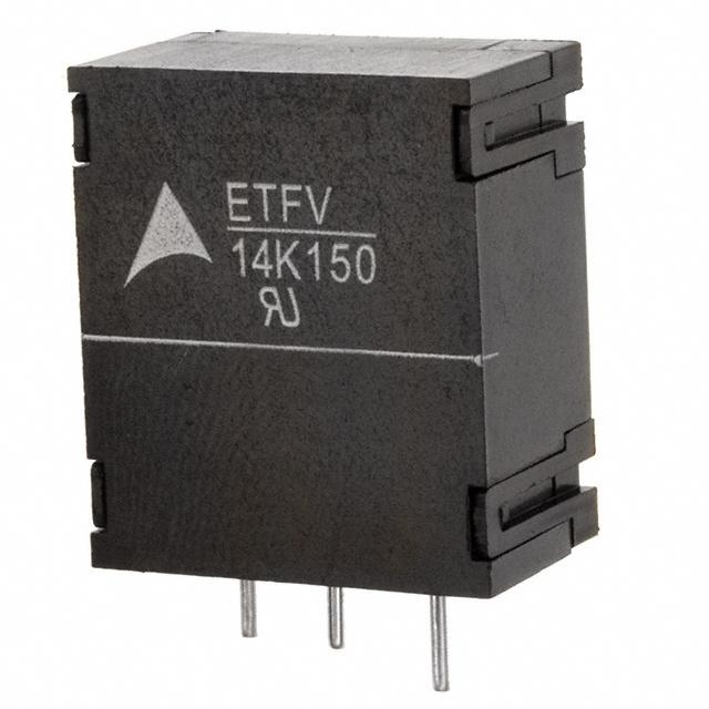
ETFV14
Date:
April 2011
© EPCOS AG 2015. Reproduction, publication and dissemination of this publication, enclosures hereto and the
information contained therein without EPCOS' prior express consent is prohibited.
EPCOS AG is a TDK Group Company.
�Housed varistors
ETFV14
ThermoFuse varistors, ETFV14 series
Construction
Round varistor element, leaded
Coating: epoxy resin, flame-retardant to UL 94 V-0
Terminals: tinned copper wire, metal compound wire
Housing: thermoplastic, flame-retardant to UL 94 V-0
Features
Wide operating voltage range 130 … 420 VRMS
Self-protected under abnormal overvoltage conditions
High-energy AdvanceD series E2
Approvals
UL
IEC
VDE
Applications
Air conditioner, refrigerator, TV, etc.
Power meter, inverter, telecom equipment, etc.
Transient voltage surge suppressors (TVSS)
Solar inverter
Delivery mode
Bulk (standard)
Typical applications
General technical data
Climatic category
Operating temperature
Storage temperature
Electric strength
Insulation resistance
Response time
Please read Cautions and warnings and
Important notes at the end of this document.
to IEC 60068-1
to IEC 61051
to IEC 61051
to IEC 61051
Page 2 of 15
40/85/56
�40 ... + 85
�40 ... + 85
≥ 2.5
≥ 100
< 25
°C
°C
kVRMS
MΩ
ns
�Housed varistors
ETFV14
ThermoFuse varistors, ETFV14 series
Electrical specifications and ordering codes
Maximum ratings (TA = 85 °C)
Ordering code
B72214T2131K101
B72214T2141K101
B72214T2151K101
B72214T2171K101
B72214T2211K101
B72214T2231K101
B72214T2251K101
B72214T2271K101
B72214T2301K101
B72214T2321K101
B72214T2351K101
B72214T2381K101
B72214T2421K101
Type
(untaped)
SIOVETFV14K130E2
ETFV14K140E2
ETFV14K150E2
ETFV14K175E2
ETFV14K210E2
ETFV14K230E2
ETFV14K250E2
ETFV14K275E2
ETFV14K300E2
ETFV14K320E2
ETFV14K350E2
ETFV14K385E2
ETFV14K420E2
VRMS
VDC
Wmax
(2 ms)
J
50
55
60
70
80
90
100
110
125
136
136
136
136
Pmax
V
170
180
200
225
270
300
320
350
385
420
460
505
560
imax
(8/20 µs)
A
6000
6000
6000
6000
6000
6000
6000
6000
6000
6000
6000
6000
6000
V
130
140
150
175
210
230
250
275
300
320
350
385
420
Vv
(1 mA)
V
205
220
240
270
330
360
390
430
470
510
560
620
680
∆Vv
(1 mA)
%
±10
±10
±10
±10
±10
±10
±10
±10
±10
±10
±10
±10
±10
vc,max
(ic)
V
340
360
395
455
545
595
650
710
775
840
910
1025
1120
ic
Ctyp
(1 kHz)
pF
650
610
570
490
410
380
350
320
300
280
260
240
220
W
0.6
0.6
0.6
0.6
0.6
0.6
0.6
0.6
0.6
0.6
0.6
0.6
0.6
Characteristics (TA = 25 °C)
Ordering code
B72214T2131K101
B72214T2141K101
B72214T2151K101
B72214T2171K101
B72214T2211K101
B72214T2231K101
B72214T2251K101
B72214T2271K101
B72214T2301K101
B72214T2321K101
B72214T2351K101
B72214T2381K101
B72214T2421K101
Type
(untaped)
SIOVETFV14K130E2
ETFV14K140E2
ETFV14K150E2
ETFV14K175E2
ETFV14K210E2
ETFV14K230E2
ETFV14K250E2
ETFV14K275E2
ETFV14K300E2
ETFV14K320E2
ETFV14K350E2
ETFV14K385E2
ETFV14K420E2
Please read Cautions and warnings and
Important notes at the end of this document.
Page 3 of 15
A
50
50
50
50
50
50
50
50
50
50
50
50
50
�Housed varistors
ETFV14
ThermoFuse varistors, ETFV14 series
Dimensional drawings
Weight
Nominal diameter
mm
14
Lead configuration
Please read Cautions and warnings and
Important notes at the end of this document.
Page 4 of 15
VRMS
V
130 ... 420
Weight
g
4.0 ... 5.6
�Housed varistors
ETFV14
ThermoFuse varistors, ETFV14 series
Reliability data
Test
Test methods/conditions
Requirement
Varistor voltage
The voltage between two terminals with To meet the specified value
the specified measuring current applied
is called VV (1 mADC @ 0.2 ... 2 s).
Clamping voltage
The maximum voltage between two
terminals with the specified standard
impulse current (8/20 µs) applied.
To meet the specified value
Endurance at upper
category temperature
1000 h at UCT
|∆V/V (1 mA)| ≤10%
Surge current derating,
8/20 µs
10 surge currents (8/20 µs), unipolar,
interval 30 s, amplitude corresponding
to derating curve for 10 impulses at
20 µs
Surge current derating,
2 ms
10 surge currents (2 ms), unipolar,
|∆V/V (1 mA)| ≤10%
interval 120 s, amplitude corresponding (measured in direction of
to derating curve for 10 impulses at
surge current)
2 ms
No visible damage
Electric strength
IEC 61051-1, test 4.9.2
After having continuously applied the
maximum allowable AC voltage at UCT
±2 °C for 1000 h, the specimen shall be
stored at room temperature and normal
humidity for 1 to 2 h.
Thereafter, the change of VV shall be
measured.
Metal balls method, 2500 VRMS, 60 s
The varistor is placed in a container
holding 1.6 ±0.2 mm diameter metal
balls such that only the terminations of
the varistor are protruding.
The specified voltage shall be applied
between both terminals of the specimen
connected together and the electrode
inserted between the metal balls.
Please read Cautions and warnings and
Important notes at the end of this document.
Page 5 of 15
|∆V/V (1 mA)| ≤10%
(measured in direction of
surge current)
No visible damage
No breakdown
�Housed varistors
ETFV14
ThermoFuse varistors, ETFV14 series
Test
Test methods/conditions
Requirement
Climatic sequence
The specimen shall be subjected to:
a) dry heat at UCT, 16 h, IEC
60068-2-2, test Ba
b) damp heat, 1st cycle:
55 °C, 93% r. H., 24 h, IEC
60068-2-30, test Db
c) cold, LCT, 2 h, IEC 60068-2-1, test
Aa
d) damp heat, additional 5 cycles:
55 °C/25 °C, 93% r. H., 24 h/cycle,
IEC 60068-2-30, test Db.
|∆V/V (1 mA)| ≤10%
Rins ≥100 MΩ
Then the specimen shall be stored at
room temperature and normal humidity
for 1 to 2 h.
Thereafter, the change of VV shall be
measured. Thereafter, insulation resistance Rins shall be measured at V = 500
V.
Rapid change of
temperature
IEC 60068-2-14, test Na, LCT/UCT,
dwell time 30 min, 5 cycles
|∆V/V (1 mA)| ≤5%
No visible damage
Damp heat, steady state
IEC 60068-2-78, test Ca
|∆V/V (1 mA)| ≤10%
The specimen shall be subjected to
Rins ≥100 MΩ
40 ±2 °C, 90 to 95% r. H. for 56 days
without load / with 10% of the maximum continuous DC operating voltage
VDC. Then stored at room temperature
and normal humidity for 1 to 2 h.
Thereafter, the change of VV shall be
measured. Thereafter, insulation resistance Rins shall be measured at V = 500
V (insulated varistors only).
Please read Cautions and warnings and
Important notes at the end of this document.
Page 6 of 15
�Housed varistors
ETFV14
ThermoFuse varistors, ETFV14 series
Test
Test methods/conditions
Solderability
IEC 60068-2-20, test Ta,
Resistance to soldering
heat
IEC 60068-2-20, test Tb, method 1A,
260 °C, 10 s:
Requirement
The inspection shall be
carried out under adequate
method 1 with modified conditions for
light with normal eyesight or
lead-free solder alloys: 245 °C, 3 s:
with the assistance of a
After dipping the terminals to a depth of
magnifier capable of giving
approximately 3 mm from the body in a
a magnification of 4 to
soldering bath of 245 °C for 3 s, the
10 times. The dipped
terminals shall be visually examined.
surface shall be covered
with a smooth and bright
solder coating with no more
than small amounts of
scattered imperfections
such as pinholes or
un-wetted or de-wetted
areas. These imperfections
shall not be concentrated in
one area.
|∆V/V (1 mA)| ≤5%
No visible damage
Each lead shall be dipped into a solder
bath having a temperature of 260 ±5 °C
to a point 2.0 to 2.5 mm from the body
of the specimen, be held there for
10 ±1 s and then be stored at room
temperature and normal humidity for
1 to 2 h.
The change of VV shall be measured
and the specimen shall be visually
examined.
Tensile strength
IEC 60068-2-21, test Ua1
|∆V/V (1 mA)| ≤5%
After gradually applying the force
specified below and keeping the unit
fixed for 10 s, the terminal shall be
visually examined for any damage.
No break of solder joint,
no wire break
Force for wire diameter:
0.6 mm = 10 N
0.8 mm = 10 N
1.0 mm = 20 N
Please read Cautions and warnings and
Important notes at the end of this document.
Page 7 of 15
�Housed varistors
ETFV14
ThermoFuse varistors, ETFV14 series
Test
Test methods/conditions
Requirement
Vibration
IEC 60068-2-6, test Fc, method B4
Frequency range: 10 … 55 Hz
Amplitude:
0.75 mm or 98 m/s2
Duration:
6 h (3 · 2 h)
Pulse:
sine wave
After repeatedly applying a single
harmonic vibration according to the
table above.
The change of VV shall be measured
and the specimen shall be visually
examined.
|∆V/V (1 mA)| ≤5%
IEC 60068-2-29, test Eb
Pulse duration:
6 ms
Max. acceleration: 400 m/s2
Number of bumps: 4000
Pulse:
half sine
IEC 60695-11-5 (needle flame test)
|∆V/V (1 mA)| ≤5%
Bump
Fire hazard
Severity: vertical 10 s
Please read Cautions and warnings and
Important notes at the end of this document.
Page 8 of 15
No visible damage
No visible damage
5 s max.
�Housed varistors
ETFV14
ThermoFuse varistors, ETFV14 series
Test
Test methods/conditions
Requirement
Abnormal overvoltage test The device is designed to meet the
limited current abnormal overvoltage
condition, outlined in section 39.4 of UL
1449, 3rd edition.
Detailed test voltage applied onto the
device for different types as in the
following table:
Type
Device
rating
V
Test
voltage
V
ETFV14K130E2
130
260
ETFV14K140E2
140
280
ETFV14K150E2
150
300
ETFV14K175E2
175
350
ETFV14K210E2
210
420
ETFV14K230E2
230
415
ETFV14K250E2
250
500
ETFV14K275E2
275
480
ETFV14K300E2
300
600
ETFV14K320E2
320
600
ETFV14K350E2
350
600
ETFV14K385E2
385
600
ETFV14K420E2
420
600
Note:
UCT = Upper category temperature
LCT = Lower category temperature
Rins = Insulation resistance
Please read Cautions and warnings and
Important notes at the end of this document.
Page 9 of 15
Any of these phenomena
shall not be observed, or
this specimen will be judged
as failed part:
1. Emission of flame, molten
metal, glowing or flaming
particles through any
openings (pre-existed or
created as a result of the
test) in the product.
2. Charring, glowing, or
flaming of the supporting
surface, tissue paper, or
cheesecloth.
3. Ignition of the enclosure.
4. Creation of any openings
in the enclosure that
result in accessibility of
live parts, when
evaluated in accordance
with accessibility of live
parts test in section 58.2
of UL1449, 3rd edition.
�Housed varistors
ETFV14
ThermoFuse varistors, ETFV14 series
v/i characteristics
v = f (i) for explanation of the characteristics refer to "General technical information", chapter 1.6.3
A = Leakage current, B = Protection level } for worst-case varistor tolerances
SIOV-ETFV14 ... E2
Please read Cautions and warnings and
Important notes at the end of this document.
Page 10 of 15
�Housed varistors
ETFV14
ThermoFuse varistors, ETFV14 series
Derating curves
Maximum surge current imax = f (tr, pulse train)
For explanation of the derating curves refer to "General technical information", section 1.8.1
SIOV-ETFV14 ... E2
Please read Cautions and warnings and
Important notes at the end of this document.
Page 11 of 15
�Housed varistors
ETFV14
ThermoFuse varistors, ETFV14 series
Cautions and warnings
General
1. EPCOS metal oxide varistors are designed for specific applications and should not be used
for purposes not identified in our specifications, application notes and data books unless otherwise agreed with EPCOS during the design-in-phase.
2. Ensure suitability of SIOVs through reliability testing during the design-in phase. SIOVs
should be evaluated taking into consideration worst-case conditions.
3. For applications of SIOVs in line-to-ground circuits based on various international and local
standards there are restrictions existing or additional safety measures required.
Storage
1. Store SIOVs only in original packaging. Do not open the package before storage.
2. Storage conditions in original packaging:
Storage temperature: �25 °C ... +45 °C,
Relative humidity: