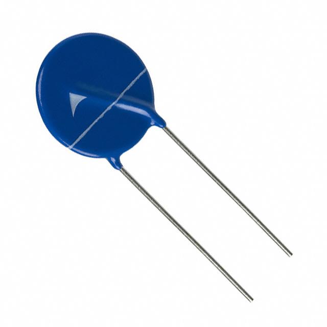
Leaded Varistors
SuperioR Series
Series/Type:
Ordering code:
SIOV-S20K150E3
B72220S3151K101
Date:
Version:
2017-10-13
a
Content of header bars 1 and 2 of data sheet will be automatically entered in headers and footers! Please fill in the table and then
change the color to "white". This ensures that the table disappears (invisible) for the customer PDF.
Don't change formatting when entering or pasting text in the table and don't add any cell or line in and to it!
Identification/Classification 1 (header 1 + top left bar):
Leaded Varistors
Identification/Classification 2
SuperioR Series
(header 2 + bottom left header bar):
Ordering code: (top right header bar)
B72220S3151K101
Series/Type: (bottom right header bar)
SIOV-S20K150E3
Preliminary data (optional):
Department:
PPD VAR PD
Date:
2017-10-13
Version:
a
Prepared by:
Leo Liu
Release signed by PE&PD&QS:
Helen Li, Dr,Yang, Mac Gao
Modifications/Remarks:
New issue
EPCOS AG 2017. Reproduction, publication and dissemination of this publication, enclosures hereto and the information
contained therein without EPCOS' prior express consent is prohibited.
EPCOS AG is a TDK Group Company.
�Leaded Varistors
SuperioR Series
B72220S3151K101
SIOV-S20K150E3
Applications
Overvoltage protection
Features
•
UL approval to UL1449 (file number E321126).
SIOV nomenclature
S
20
K
150
E3
=
=
=
=
=
Disk type
Rated disk diameter
Tolerance of VV at 1mA: ±10%
Max. AC operating voltage
SuperioR series
General technical data
Climatic category
Operating temperature
Storage temperature
Electric strength
Insulation resistance
to IEC 60068-1
to IEC 61051
to IEC 61051
PPD VAR PD
Please read Cautions and warnings and
Important notes at the end of this document.
40/105/56
-40…+105 °C
-40…+125 °C
≥2.5 kVRMS
≥100 MΩ
2017-10-13
Page 2 of 11
�Leaded Varistors
SuperioR Series
B72220S3151K101
SIOV-S20K150E3
Dimensional drawings in mm
bmax
hmax
smax
e
atyp
lmin
∅d
1)
=
=
=
=
=
=
=
21.5
25.5
5.0
10.0 ±0.5
2.1
25.0
1.0 ±0.05
1) seating plane in accordance
with IEC 60717
Electrical data
Maximum Ratings (105 °C):
Max. AC operating voltage
Max. DC operating voltage
Surge current (8/20 µs)
Energy absorption (2 ms)
Average power dissipation
Characteristics (25 °C):
Varistor voltage at 1 mA
Clamping voltage at 100 A (8/20 µs)
Typ. capacitance at 1 kHz
1 time
1 time
VRMS
VDC
Imax
Wmax
Pmax
=
=
=
=
=
150 V
200 V
12000 A
155 J
1.0 W
VV
VC,max
C
=
=
=
240 V ±10%
395 V
2050 pF
PPD VAR PD
Please read Cautions and warnings and
Important notes at the end of this document.
2017-10-13
Page 3 of 11
�Leaded Varistors
SuperioR Series
B72220S3151K101
SIOV-S20K150E3
V/I Characteristic
VAR9560A
5000
v
4000
V
2000
1000
800
600
400
200
100
80
60
50
10 -5
10 -4
10 -3
10 -2
10 -1
10 0
10 1
10 2
10 3
A 10 4
i
Derating
PPD VAR PD
Please read Cautions and warnings and
Important notes at the end of this document.
2017-10-13
Page 4 of 11
�Leaded Varistors
SuperioR Series
B72220S3151K101
SIOV-S20K150E3
Reliability Data Electrical
Characteristics
Test Methods/Description
Specifications
Varistor
Voltage
The voltage between two terminals with the
specified measuring current applied is called Vv (1
mADC @ 0.2 … 2 s).
To meet the specified
value.
Clamping
Voltage
The maximum voltage between two terminals with
the specified standard impulse current (8/20µs)
illustrated below applied.
To meet the specified
value.
Surge current
derating,
8/20 µs
10 surge currents (8/20 µs), unipolar, interval 30 s,
amplitude corresponding to derating curve for 10
impulses at 20 µs
|∆V/V (1 mA)| ≤10%
(measured in direction of
surge current)
No visible damage
Surge current
derating,
2 ms
10 surge currents (2ms), unipolar, interval 120s,
amplitude corresponding to derating curve for 10
impulses at 2 ms
|∆V/V (1 mA)| ≤10%
(measured in direction of
surge current)
No visible damage
PPD VAR PD
Please read Cautions and warnings and
Important notes at the end of this document.
2017-10-13
Page 5 of 11
�Leaded Varistors
SuperioR Series
B72220S3151K101
SIOV-S20K150E3
Reliability Data Mechanical
Characteristics
Test Methods/Description
Specifications
Tensile strength
IEC 60068-2-21, test Ua1
After gradually applying the force specified below
and keeping the unit fixed for 10 s, the terminal shall
be visually examined for any damage.
Force for wire diameter:
0.6 mm = 10 N
0.8 mm = 10 N
1.0 mm = 20 N
|∆V/V (1 mA)| ≤5%
No break of solder joint,
no wire break
Vibration
IEC 60068-2-6, test Fc, method B4
Frequency range:
10 .... 55 Hz
Amplitude:
0.75 mm or 98 m/s²
Duration:
6 h (3 x 2 h)
Pulse:
sine wave
After repeatedly applying a single harmonic vibration
according to the table above, the change of Vv shall
be measured and the part shall be visually
examined.
|∆V/V (1 mA)| ≤5%
No visible damage
Solderability
IEC 60068-2-20, test Ta, method 1 with modified
conditions for lead-free solder alloys: 245°C, 3 s:
After dipping the terminals to a depth of
approximately 3 mm from the body in a soldering
bath of 245 °C for 3 s, the terminals shall be visually
examined.
The inspection shall be
carried out under
adequate light with normal
eyesight or with the
assistance of a magnifier
capable of giving a
magnification of 4 to 10
times. The dipped surface
shall be covered with a
smooth and bright solder
coating with no more than
small amounts of
scattered imperfections
such as pinholes or unwetted or de-wetted
areas. These
imperfections shall not be
concentrated in one area.
PPD VAR PD
Please read Cautions and warnings and
Important notes at the end of this document.
2017-10-13
Page 6 of 11
�Leaded Varistors
SuperioR Series
B72220S3151K101
SIOV-S20K150E3
Characteristics
Test Methods/Description
Specifications
Resistance to
soldering heat
IEC 60068-2-20, test Tb, method 1A, 260 °C, 10 s:
Each lead shall be dipped into a solder bath having
a temperature of 260 ±5 °C to a point 2.0 to 2.5 mm
from the body of the unit, be held there for 10 ±1 s
and then be stored at room temperature and normal
humidity for 1 to 2 hours. The change of Vv shall be
measured and the part shall be visually examined.
|∆V/V (1 mA)| ≤5%
No visible damage
Bump
IEC 60068-2-29, test Eb
Pulse duration:
6 ms
2
Max. acceleration:
400m/s
Number of bumps:
4000
Pulse:
half sine
|∆V/V (1 mA)| ≤5%
No visible damage
Fire hazard
IEC 60695-11-5 (needle flame test)
Severity: vertical 10 s
5 s max.
Electric strength
IEC 61051-1, test 4.9.2
Metal balls method, 2500 VRMS, 60 s
No breakdown
The varistor is placed in a container holding 1.6 ±0.2
mm diameter metal balls such that only the
terminations of the varistor are protruding.
The specified voltage shall be applied between both
terminals of the specimen connected together and
the electrode inserted between the metal balls.
PPD VAR PD
Please read Cautions and warnings and
Important notes at the end of this document.
2017-10-13
Page 7 of 11
�Leaded Varistors
SuperioR Series
B72220S3151K101
SIOV-S20K150E3
Reliability Data Environmental
Characteristics
Test Methods/Description
Endurance at upper
category temperature
1000 h at UCT
After having continuously applied the maximum
allowable voltage at UCT ±2 °C for 1000 h, the
specimen shall be stored at room temperature and
normal humidity for 1 to 2 h.
Thereafter, the change of Vv shall be measured.
|∆V/V (1 mA)| ≤10%
Damp heat, steady
state
IEC 60068-2-78, test Ca
|∆V/V (1 mA)| ≤10%
Rins ≥100 MΩ
The specimen shall be subjected to 40 ±2 °C, 90 to
95 % r.H. for 56 days without load / with 10% of the
maximum continuous DC operating voltage VDC.
Then stored at room temperature and normal
humidity for 1 to 2 h.
Thereafter, the change of Vv shall be measured.
Thereafter, insulation resistance Rins shall be
measured at V = 500 V (insulated varistors only).
Specifications
Climatic sequence
The specimen shall be subjected to:
a) IEC 60068-2-2, test Ba, dry heat at UCT, 16 h
b) IEC 60068-2-30, test Db, damp heat, 1st cycle:
55 °C, 93% r.H., 24 h
c) IEC 60068-2-1, test Aa, cold, LCT, 2 h
d) IEC 60068-2-30, test Db, damp heat, additional 5
cycles: 55 °C/25 °C, 93% r.H., 24 h/cycle.
Then the specimen shall be stored at room
temperature and normal humidity for 1 to 2 h.
Thereafter, the change of Vv shall be measured.
Thereafter, insulation resistance Rins shall be
measured at V = 500 V.
|∆V/V (1 mA)| ≤10%
Rins ≥100 MΩ
Rapid change of
temperature
-40°C to 125°C, dwell time 10 min, 1000 cycles
|∆V/V (1 mA)| ≤5%
No visible damage
Note:
UCT = Upper category temperature
LCT = Lower category temperature
Rins = Insulation resistance
PPD VAR PD
Please read Cautions and warnings and
Important notes at the end of this document.
2017-10-13
Page 8 of 11
�Leaded Varistors
SuperioR Series
B72220S3151K101
SIOV-S20K150E3
Cautions and warnings
General
1.
EPCOS metal oxide varistors (SIOVs) are designed for specific applications and should not be used for
purposes not identified in our specifications, application notes and data books unless otherwise agreed with
EPCOS during the design-in-phase.
2.
Ensure suitability of SIOVs through reliability testing during the design-in phase. The SIOVs should be
evaluated taking into consideration worst-case conditions.
3.
For applications of SIOVs in line-to ground circuits based on various international and local standards there
are restrictions existing or additional safety measures required.
Storage
1.
Store SIOVs only in original packaging. Do not open the package before storage.
2.
Storage conditions in original packaging:
Storage temperature:
Relative humidity:
Dew precipitation:
-25 °C … +45 °C