C A P A C I T O R S
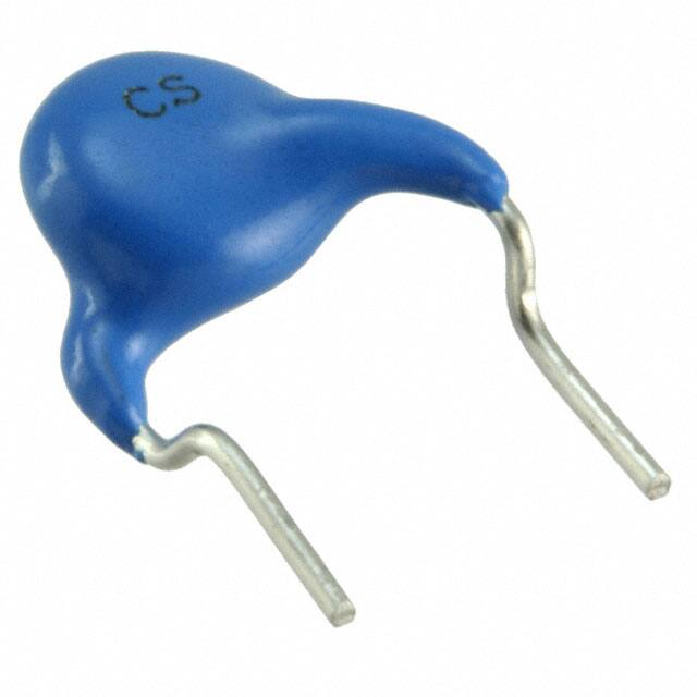
Disc type capacitors with leads
High voltage ceramic capacitors, commercial grade, safety standard approved
REACH
SVHC-Free
RoHS
Cl
Br
Pb
Halogen
Free
Lead
Free
CS45 series
FEATURES
Compliant with IEC and the safety standards of various countries.
Withstand voltage is 2,600V AC.
Flame-resistant reinforced outer insulation prevents fires, electrical shock, and other potential hazards.
Conform to RoHS directive due to lead(Pb) free of lead-wire and internal solder material.
Compatible with halogen-free external resin coating.
APPLICATION
Y capacitor for AC adapter, charger, power supplies
PART NUMBER CONSTRUCTION
*
CS45
-E
2GA
102
M
Series
name*
Temperature
characteristics
Rated voltage
Nominal
capacitance
Capacitance
tolerance
-SL
+350 to
–1,000ppm/°C
-B
-E
-F
±10%
+20, –55%
+30, –80%
2GA
X1:440V AC
Y2:300V AC
-
□
K
A
Lead-wire type
Application
classification
Internal code
100
10pF
J
±5%
G
Long lead
221
220pF
K
±10%
N
Short lead
472
4,700pF
M
±20%
V
Taping
K
Safety
standard
approved
A
Halogen-free
Please refer to P-3 about the product dimensions.
OPERATING TEMPERATURE RANGE
Temperature characteristics
Operating temperature (°C)
Storage temperature (°C)*
SL
–40 to 125
–40 to 125
B
–40 to 125
–40 to 125
E
–40 to 125
–40 to 125
F
–40 to 125
–40 to 125
The maximum operating temperature of +125°C includes capacitor self-generated heat of up to 20°C.
* After capacitor is mounted on board, the storage temperature range is applied.
STANDARD LEAD-WIRE SHAPES
Dimemsions in mm
T
25min.
*2
T
4max.
4max.
5±1
*2
Vertical kink
D*1
ø0.6±0.05
F
*2
16+1.5
–0.5
D*1
4max.
4max.
T
Symbols V : Taping
4max.
D*1
Symbols N : Bulk/short leads
5±1
Symbols G : Bulk/long leads
F
F
ø0.6±0.05
ø0.6±0.05
TDK’s standard product is vertical kink. TDK recommends short leads for bulk products.
*1 Body diameter (D) is reference value if D is smaller than maximum dimension of lead to lead distance (F).
*2 Coating on leads shall not extend beyond the bottom of vertical kink.
RoHS Directive Compliant Product: See the following for more details. https://product.tdk.com/en/environment/rohs/index.html
Halogen-free: Indicate that Cl content is less than 900ppm, Br content is less than 900ppm, and that the total Cl and Br content is less than 1500ppm.
Please be sure to request delivery specifications that provide further details on the features and specifications of the products for proper and safe use.
Please note that the contents may change without any prior notice due to reasons such as upgrading.
(1/5)
20210802
leaddisc_commercial_cs45_en.fm
�C A P A C I T O R S
Overview of CS45 series
CERTIFIED STATUS OF VARIOUS COUNTRIES
Safety
standard
ENEC
UL
cUL/CSA
SAA
CQC
IEC standard No.
Standard No.
Temperature
characteristics
Sub-class
Rated
voltage
X1, Y2
X1:440V AC
Y2:300V AC
EN 60384-14
UL60384-14
IEC 60384-14
AS3250
IEC 60384-14
KTL
SL,B,E,F
X1
Y2
K60384-14
440V AC
300V AC
Approval report No.*
Taiwan
Xiamen
ENEC-01049
E37861
CS6268
CQC14001112768 CQC14001112449
SZ03001-12006
SU03047-12006
SZ03001-12008
SU03047-12008
* Certificate numbers shall be changed owing to the revisions of the related standards and renewal of certificate.
RECOMMENDED FLOW PROFILE
Soldering
Preheating
Natural
cooling
T: Temperature
T2
T1
t1
t2
t3
t: Time
Preheating
Temp.
T1
110°C min.
Time
t1
30 to 60s.
Peak
Temp.
T2
260°C
Time
t2
Within 10s.
Natural cooling
Time
t3
Over 60s.
Please be sure to request delivery specifications that provide further details on the features and specifications of the products for proper and safe use.
Please note that the contents may change without any prior notice due to reasons such as upgrading.
(2/5)
20210802
leaddisc_commercial_cs45_en.fm
�C A P A C I T O R S
CS45 type
MARKINGS
Item
1.Series
2.Nominal capacitance
3.Capacitance tolerance
4.Rated voltage Eac
Markings
CS
10
J
440∼X1
300∼Y2
Description
CS45 series
10pF
±5%
X1:440V AC
Y2:300V AC
Production base code
04
2020.4*
5.TDK’s trademark
6.Date code
Marking examples
Front
Back
CS
10J
04
(Marking position is reference.)
* Year
*The
and month of production: last digit of year + month denoted by 1, 2, 3, 4, 5, 6, 7, 8, 9, O (October), N (November), or D (December).
expression has become simplified due to a revision in the standards.
RATED VOLTAGE Eac: X1:440V, Y2:300V
CAPACITANCE AND DIMENSIONS
Temperature
characteristics
Capacitance
Capacitance
tolerance
Dimensions (mm)
F
Dmax. * Tmax. (applied
to bulk)
F
(applied
to taping)
Part numbers
Bulk/long leads
(Symbols: G)
Bulk/short leads
(Symbols: N)
Taping
(Symbols: V)
SL
10pF
±5%
(7.0)
5.0
7.5±1.5
7.5±0.8
CS45SL2GA100J-GKA
CS45SL2GA100J-NKA
CS45SL2GA100J-VKA
SL
15pF
±5%
(7.0)
5.0
7.5±1.5
7.5±0.8
CS45SL2GA150J-GKA
CS45SL2GA150J-NKA
CS45SL2GA150J-VKA
SL
22pF
±5%
(7.0)
5.0
7.5±1.5
7.5±0.8
CS45SL2GA220J-GKA
CS45SL2GA220J-NKA
CS45SL2GA220J-VKA
SL
33pF
±5%
(7.0)
5.0
7.5±1.5
7.5±0.8
CS45SL2GA330J-GKA
CS45SL2GA330J-NKA
CS45SL2GA330J-VKA
SL
47pF
±5%
(7.0)
5.0
7.5±1.5
7.5±0.8
CS45SL2GA470J-GKA
CS45SL2GA470J-NKA
CS45SL2GA470J-VKA
SL
68pF
±5%
(7.5)
5.0
7.5±1.5
7.5±0.8
CS45SL2GA680J-GKA
CS45SL2GA680J-NKA
CS45SL2GA680J-VKA
B
100pF
±10%
(6.5)
5.0
7.5±1.5
7.5±0.8
CS45-B2GA101K-GKA
CS45-B2GA101K-NKA
CS45-B2GA101K-VKA
B
150pF
±10%
(6.5)
5.0
7.5±1.5
7.5±0.8
CS45-B2GA151K-GKA
CS45-B2GA151K-NKA
CS45-B2GA151K-VKA
B
220pF
±10%
(6.5)
5.0
7.5±1.5
7.5±0.8
CS45-B2GA221K-GKA
CS45-B2GA221K-NKA
CS45-B2GA221K-VKA
B
330pF
±10%
(6.5)
5.0
7.5±1.5
7.5±0.8
CS45-B2GA331K-GKA
CS45-B2GA331K-NKA
CS45-B2GA331K-VKA
B
470pF
±10%
(7.0)
5.0
7.5±1.5
7.5±0.8
CS45-B2GA471K-GKA
CS45-B2GA471K-NKA
CS45-B2GA471K-VKA
B
680pF
±10%
(8.0)
5.0
7.5±1.5
7.5±0.8
CS45-B2GA681K-GKA
CS45-B2GA681K-NKA
CS45-B2GA681K-VKA
E
1,000pF
±20%
(6.5)
5.0
7.5±1.5
7.5±0.8
CS45-E2GA102M-GKA
CS45-E2GA102M-NKA
CS45-E2GA102M-VKA
E
1,500pF
±20%
(7.5)
5.0
7.5±1.5
7.5±0.8
CS45-E2GA152M-GKA
CS45-E2GA152M-NKA
CS45-E2GA152M-VKA
E
2,200pF
±20%
(8.0)
5.0
7.5±1.5
7.5±0.8
CS45-E2GA222M-GKA
CS45-E2GA222M-NKA
CS45-E2GA222M-VKA
E
3,300pF
±20%
10.0
5.0
7.5±1.5
7.5±0.8
CS45-E2GA332M-GKA
CS45-E2GA332M-NKA
CS45-E2GA332M-VKA
E
4,700pF
±20%
11.0
5.0
7.5±1.5
7.5±0.8
CS45-E2GA472M-GKA
CS45-E2GA472M-NKA
CS45-E2GA472M-VKA
F
10,000pF
±20%
14.5
5.0
7.5±1.5
7.5±0.8
CS45-F2GA103M-GKA
CS45-F2GA103M-NKA
CS45-F2GA103M-VKA
* The values in parentheses "( )" are reference values.
Click the part number for details.
• Please refer to p-4 about the taping dimemsions.
• For more information about products with other capacitance or other data, please contact us.
Please be sure to request delivery specifications that provide further details on the features and specifications of the products for proper and safe use.
Please note that the contents may change without any prior notice due to reasons such as upgrading.
(3/5)
20210802
leaddisc_commercial_cs45_en.fm
�C A P A C I T O R S
CS45 type
TAPING DIMENSIONS
P
T
D*1
P2
h
F
C*2
S
t
W0
W
L
W1
H0
P1
W2
H0
A
h
P0
D0
ød
Item
Symbols
Dimensions (mm)
Body diameter
D
Refer to P-3
Body thickness
Lead-wire diameter
Pitch of component
Feed hole pitch
T
ød
P
P0
Refer to P-3
0.6±0.05
15.0±1.0
15.0±0.3
3.75±0.7
7.5±1.3
7.5±0.8
Feed hole center to lead-wire
P1
Feed hole center to component center
P2
Lead-to lead distance
F
Component alignment
Carrier tape width
Adhesive tape width
Hole position
Adhesive tape position
Bottom of kink from tape center
Lead-wire protrusion
Feed hole diameter
Carrier tape thickness
(Including adhesive tape)
Length of snipped lead-wire
Coating on lead-wire
Height of kink
Spring action
Dh
W
W0
W1
W2
H0
Remarks
*1 Body diameter (D) is reference value if D is smaller than maximum dimension of lead to lead distance (F).
Including the slant of body
Excepting the tape splicing part
Including the slanting body due to bending lead-wire
Measuring point is bottom kink
D0
0 ±2.0
18.0+1.0,–0.5
10.0 Min.
9.0±0.5
4.0 Max.
16.0+1.5,–0.5
1.0 Max.
4.0±0.2
t
0.6±0.3
Including adhesive tape
L
C
A
S
11.0 Max.
4.0 Max.
4.0 Max.
2.0 Max.
*2 Coating on leads shall not extend beyond the bottom of vertical kink.
Measuring point is bottom kink
AMMO PACK INNER BOX SIZE
Including the slanting body due to bending lead-wire
Adhesive tape do not stick out the tape
PACKAGE QUANTITY
Package quantity
Type
Bulk (pieces / bag)
Taping (pieces / box)
1000
1000
320max.
CS45
x.
ma
340max.
60
Dimensions in mm
Please be sure to request delivery specifications that provide further details on the features and specifications of the products for proper and safe use.
Please note that the contents may change without any prior notice due to reasons such as upgrading.
(4/5)
20210802
leaddisc_commercial_cs45_en.fm
�C A P A C I T O R S
REMINDERS FOR USING THESE PRODUCTS
Before using these products, be sure to request the delivery specifications.
SAFETY REMINDERS
Please pay sufficient attention to the warnings for safe designing when using this products.
REMINDERS
Do not use or store in locations where there are conditions such as gas corrosion (salt, acid, alkali, etc.).
Before soldering, be sure to preheat components.
The preheating temperature should be set so that the temperature difference between the solder temperature and product temperature
does not exceed 150°C.
Soldering corrections after mounting should be within the range of the conditions determined in the specifications.
If overheated, a short circuit, performance deterioration, or lifespan shortening may occur.
Self heating (temperature increase) occurs when the power is turned ON, so the tolerance should be sufficient for the set thermal
design.
Do not use for a purpose outside of the contents regulated in the delivery specifications.
The products listed on this catalog are intended for use in general electronic equipment (AV equipment, telecommunications equipment, home appliances, amusement equipment, computer equipment, personal equipment, office equipment, measurement equipment, industrial robots) under a normal operation and use condition.
The products are not designed or warranted to meet the requirements of the applications listed below, whose performance and/or quality require a more stringent level of safety or reliability, or whose failure, malfunction or trouble could cause serious damage to society,
person or property.
If you intend to use the products in the applications listed below or if you have special requirements exceeding the range or conditions
set forth in the each catalog, please contact us.
(1) Aerospace/aviation equipment
(2) Transportation equipment (cars, electric trains, ships, etc.)
(3) Medical equipment
(4) Power-generation control equipment
(5) Atomic energy-related equipment
(6) Seabed equipment
(7) Transportation control equipment
(8) Public information-processing equipment
(9) Military equipment
(10) Electric heating apparatus, burning equipment
(11) Disaster prevention/crime prevention equipment
(12) Safety equipment
(13) Other applications that are not considered general-purpose
applications
Please refer to the guideline of notabilia for fixed ceramic capacitors issued by JEITA(Japan Electronics and Information Technology
Association, EIAJ RCR-2335).
This guideline describes general precautions* for using fixed ceramic capacitors. Please carefully confirm it and use capacitors safely.
* Items for check, explanation/reason/concrete example and failure examples, etc.
When designing your equipment even for general-purpose applications, you are kindly requested to take into consideration securing protection circuit/device or providing backup circuits in your equipment.
Please be sure to request delivery specifications that provide further details on the features and specifications of the products for proper and safe use.
Please note that the contents may change without any prior notice due to reasons such as upgrading.
(5/5)
20210802
leaddisc_commercial_cs45_en.fm
�