ICP-10125 Datasheet
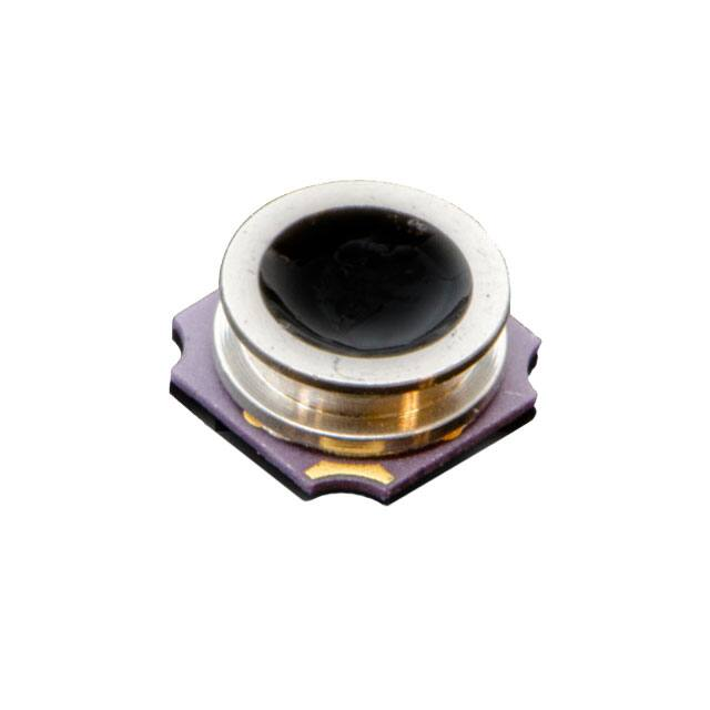
High Accuracy, Low Power, 10atm Waterproof Barometric Pressure
and Temperature Sensor IC
GENERAL INFORMATION
FEATURES
The ICP-10125 pressure sensor is based on MEMS capacitive
technology, which provides ultra-low noise at the lowest
power, enabling industry leading relative accuracy, sensor
throughput, and temperature stability. The pressure sensor
can measure pressure differences with an accuracy of ±1 Pa,
an accuracy enabling altitude measurement differentials as
small as 8.5 cm, less than the height of a single stair step.
Consuming only 1.3 µA @1 Hz, the device is available in a
small footprint 3.55 mm x 3.55 mm x 1.45 mm chimney
package with waterproofing gel providing IPx8 waterproofing
to 10 ATM. The ICP-10125 is ideally suited for wearable
fitness monitoring and battery powered IoT.
The ICP-10125 offers an industry leading temperature
coefficient offset of ±0.5 Pa/C. The combination of high
accuracy, low power, temperature stability, waterproofing in
a small footprint enables higher performance barometric
pressure sensing for sports activity identification and mobile
indoor/outdoor navigation.
DEVICE INFORMATION
PART
NUMBER
PACKAGE
LID OPENING
ICP-10125
3.55x3.55x1.45mm
HTCC-10L
Gel filled HTCC package with
machined lid; IPx8
waterproofing to 10 ATM
•
•
•
•
•
•
•
•
•
•
•
Pressure operating range: 30 to 110 kPa
Noise and current consumption
o 0.4 Pa @ 10.4 µA (ULN mode)
o 0.8 Pa @ 5.2 µA (LN mode)
o 3.2 Pa @ 1.3 µA (LP mode)
Pressure Sensor Relative Accuracy: ±1 Pa for any
10 hPa change over 950 hPa-1050 hPa at 25C
Pressure Sensor Absolute Accuracy: ±1 hPa over
950 hPa-1050 hPa, 0C to 65C
Pressure Sensor Temperature Coefficient Offset:
±0.5 Pa/C over 25C to 45C at 100 kPa
Temperature Sensor Absolute Accuracy: ±0.4C
IPx8: Waterproof to 10 ATM
Temperature operating range: -40 °C to 85 °C
Host Interface: I2C at up to 400 kHz
Single Supply voltage: 1.8V ±5%
RoHS and Green compliant
TYPICAL OPERATING CIRCUIT
Denotes RoHS and Green-Compliant Package
BLOCK DIAGRAMS
AP/HUB
I2C
ICP-10125
APPLICATIONS
•
•
•
•
•
•
Smart watches
Leisure, Sports, and Fitness Activity Monitoring for
Wearable Sensors
Altimeters and barometers for portable devices
Indoor/Outdoor Navigation (dead-reckoning,
floor/elevator/step detection)
Home and Building Automation
Weather Forecasting
InvenSense, Inc. reserves the right to change
specifications and information herein without notice
unless the product is in mass production and the
datasheet has been designated by InvenSense in writing
as subject to a specified Product / Process Change
Notification Method regulation.
InvenSense, a TDK Group Company
1745 Technology Drive, San Jose, CA 95110 U.S.A
+1(408) 988–7339
invensense.tdk.com
Document Number: DS-000329
Revision: 1.1
Release Date: 04/09/2021
�ICP-10125
TABLE OF CONTENTS
GENERAL INFORMATION ..................................................................................................................................................1
DEVICE INFORMATION .....................................................................................................................................................1
BLOCK DIAGRAMS...........................................................................................................................................................1
APPLICATIONS ................................................................................................................................................................1
FEATURES .....................................................................................................................................................................1
TYPICAL OPERATING CIRCUIT ............................................................................................................................................1
1
INTRODUCTION .............................................................................................................................................. 5
1.1
1.2
2
PRESSURE AND TEMPERATURE SENSOR SPECIFICATIONS .............................................................................. 6
2.1
2.2
2.3
2.4
2.5
3
INTERFACE SPECIFICATIONS .................................................................................................................................11
PIN OUT DIAGRAM AND SIGNAL DESCRIPTION........................................................................................................11
TYPICAL OPERATING CIRCUIT ..............................................................................................................................12
BILL OF MATERIALS FOR EXTERNAL COMPONENTS...................................................................................................13
OPERATION AND COMMUNICATION ............................................................................................................ 14
5.1
5.2
5.3
5.4
5.5
5.6
5.7
5.8
5.9
5.10
5.11
5.12
5.13
5.14
6
ELECTRICAL CHARACTERISTICS ...............................................................................................................................8
ABSOLUTE MAXIMUM RATINGS.............................................................................................................................9
SENSOR SYSTEM TIMING ......................................................................................................................................9
I2C TIMING CHARACTERIZATION ..........................................................................................................................10
APPLICATIONS INFORMATION ..................................................................................................................... 11
4.1
4.2
4.3
4.4
5
OPERATION RANGES ...........................................................................................................................................6
OPERATION MODES ............................................................................................................................................6
PRESSURE SENSOR SPECIFICATIONS ........................................................................................................................7
TEMPERATURE SENSOR SPECIFICATIONS ..................................................................................................................7
RECOMMENDED OPERATION CONDITIONS ...............................................................................................................7
ELECTRICAL SPECIFICATIONS .......................................................................................................................... 8
3.1
3.2
3.3
3.4
4
PURPOSE AND SCOPE ..........................................................................................................................................5
PRODUCT OVERVIEW...........................................................................................................................................5
POWER-UP AND COMMUNICATION START ............................................................................................................14
MEASUREMENT COMMANDS ..............................................................................................................................14
STARTING A MEASUREMENT ...............................................................................................................................14
SENSOR BEHAVIOR DURING MEASUREMENT ..........................................................................................................14
READOUT OF MEASUREMENT RESULTS .................................................................................................................15
SOFT RESET .....................................................................................................................................................15
READ-OUT OF ID REGISTER .................................................................................................................................15
CHECKSUM CALCULATION ..................................................................................................................................16
CONVERSION OF SIGNAL OUTPUT ........................................................................................................................16
READ-OUT OF CALIBRATION PARAMETERS .............................................................................................................18
SAMPLE CODE: EXAMPLE C SYNTAX .....................................................................................................................18
SAMPLE CODE: CONVERSION FORMULA (EXAMPLE PYTHON SYNTAX) ..........................................................................20
SAMPLE CODE: USING CONVERSION FORMULA (EXAMPLE PYTHON SYNTAX).................................................................21
COMMUNICATION DATA SEQUENCES....................................................................................................................22
ASSEMBLY .................................................................................................................................................... 23
6.1
IMPLEMENTATION AND USAGE RECOMMENDATIONS ...............................................................................................23
6.1.1
Soldering ..............................................................................................................................................23
Document Number: DS-000329
Revision: 1.1
Page 2 of 30
�ICP-10125
6.1.2
Chemical Exposure and Sensor Protection ...........................................................................................23
7
PACKAGE DIMENSIONS ................................................................................................................................ 24
8
TAPE AND REEL SPECIFICATION .................................................................................................................... 26
9
ORDERING GUIDE ......................................................................................................................................... 27
10
REFERENCES ............................................................................................................................................. 28
11
REVISION HISTORY ................................................................................................................................... 29
Document Number: DS-000329
Revision: 1.1
Page 3 of 30
�ICP-10125
LIST OF FIGURES
Figure 1. Digital I/O Pads Timing ................................................................................................................ 10
Figure 2. Pin Out Diagram for ICP-10125, 3.55mm x 3.55mm x 1.45mm HTCC ....................................... 11
Figure 3. ICP-10125 Application Schematic ............................................................................................... 12
Figure 4. Typical Application Circuit ............................................................................................................ 13
Figure 5. Communication Data Sequences ................................................................................................ 22
Figure 6. ICP-10125 Package Diagram ...................................................................................................... 24
Figure 7. ICP-10125 recommended PCB land pattern ............................................................................... 25
Figure 8. ICP-10125 Artwork....................................................................................................................... 25
Figure 9. ICP-10125 Tape Dimensions ................................................................................................... 26
Figure 10. Tape and Reel Orientation ......................................................................................................... 26
LIST OF TABLES
Table 1. Operation Ranges ........................................................................................................................... 6
Table 2. Operation Modes............................................................................................................................. 6
Table 3. Pressure Sensor Specifications ...................................................................................................... 7
Table 4. Temperature Sensor Specifications ................................................................................................ 7
Table 5. Electrical Specifications .................................................................................................................. 8
Table 6. Absolute Maximum Ratings ............................................................................................................ 9
Table 7. System Timing Specifications ......................................................................................................... 9
Table 8. I2C Parameters Specification ........................................................................................................ 10
Table 9. Signal Descriptions ....................................................................................................................... 11
Table 10. Bill of Materials ............................................................................................................................ 13
Table 11. ICP-10125 I2C Device Address ................................................................................................... 14
Table 12. Measurement Commands ........................................................................................................... 14
Table 13. Soft Reset Command .................................................................................................................. 15
Table 14. Read-Out Command of ID Register ............................................................................................ 15
Table 15. 16-bit ID Structure ....................................................................................................................... 16
Table 16. ICP-10125 I2C CRC Properties ................................................................................................... 16
Document Number: DS-000329
Revision: 1.1
Page 4 of 30
�ICP-10125
1 INTRODUCTION
1.1
PURPOSE AND SCOPE
This document is a preliminary product specification, providing a description, specifications, and design related
information for the ICP-10125 Pressure Sensor.
Specifications are subject to change without notice. Final specifications will be updated based upon
characterization of production silicon.
1.2
PRODUCT OVERVIEW
The ICP-10125 is an ultra-low power, low noise, digital output barometric pressure and temperature sensor IC. It is
based on an innovative MEMS capacitive pressure sensor technology that can measure pressure differences with
an accuracy of ±1 Pa at the industry’s lowest power. The high accuracy MEMS capacitive pressure sensor is capable
of measuring altitude differentials down to 8.5 cm without the penalty of increased power consumption or
reduced sensor throughput.
The capacitive pressure sensor has a ±1 hPa absolute accuracy over its full range of 300 hPa -1100 hPa. The
pressure sensor has an embedded temperature sensor and 400 kHz I2C bus for communication. For power-critical
applications, the ICP-10125 features a low power mode of 1.3 µA at a noise of 3.2 Pa or for high performance
applications, it features a low noise mode of 0.8 Pa while only consuming 5.2 µA.
The device is available in a small footprint 3.55 mm x 3.55 mm x 1.45 mm chimney package with waterproofing gel
providing IPx8 waterproofing to 10 ATM.
The ICP-10125 also offers industry leading temperature stability of the pressure sensor with a temperature
coefficient offset of ±0.5 Pa/C. The high accuracy, temperature stability, and market leading low power
consumption of 1.3 µA @1 Hz offered by ICP-10125 makes it ideally suited for applications such as mobile phones,
drone flight control and stabilization, indoor/outdoor navigation (elevator, floor, and stair step detection), sports
and fitness activity monitoring, and battery-powered IoT.
Document Number: DS-000329
Revision: 1.1
Page 5 of 30
�ICP-10125
2 PRESSURE AND TEMPERATURE SENSOR SPECIFICATIONS
2.1
OPERATION RANGES
The sensor shows best performance when operated within the recommended temperature and pressure range
(hereafter called normal conditions) of 0°C – 45°C and 95 kPa – 105 kPa, respectively. The following ranges are
defined for the device:
OPERATION RANGE
PRESSURE (KPA)
TEMPERATURE (C)
Normal
95 to 105
0 to 45
Extended
30 to 110
-20 to 65
Maximum
25 to 115
-40 to 85
Table 1. Operation Ranges
2.2
OPERATION MODES
The sensor can be operated in up to four different measurement modes to satisfy different requirements for
power consumption vs. noise, accuracy, and measurement frequency. An overview of the operation modes is given
in Table 2.
PARAMETER
Conversion Time
Current
Consumption
Pressure RMS
Noise
CONDITIONS
Time between sending last bit
of measurement command,
and sensor data ready for
measurement
1 Hz ODR
Valid for P = 100 kPa, T = 25°C,
and U = 1.8V
SENSOR MODE
Low Power (LP)
Normal (N)
TYP
1.6
5.6
MAX
1.8
6.3
UNITS
NOTES
1
1
Low Noise (LN)
Ultra Low Noise
(ULN)
Low Power (LP)
Normal (N)
Low Noise (LN)
Ultra Low Noise
(ULN)
Low Power (LP)
Normal
Low Noise (LN)
Ultra Low Noise
(ULN)
20.8
23.8
ms
1
83.2
94.5
1.3
2.6
5.2
1
µA
10.4
3.2
1.6
0.8
Pa
0.4
Table 2. Operation Modes
Notes:
1.
Guaranteed by design.
Low Power modes supports ODR greater than 500 Hz while the Low Noise mode provides industry leading RMS
noise at a fast 40 Hz ODR. Further decrease in noise may be achieved by software oversampling and filtering
through customer’s software implementation or custom TDK InvenSense operation modes available upon request.
Document Number: DS-000329
Revision: 1.1
Page 6 of 30
�ICP-10125
2.3
PRESSURE SENSOR SPECIFICATIONS
Pressure sensor specifications are given in Table 3. Default conditions of 25 °C and 1.8V supply voltage apply, unless
otherwise stated.
PARAMETER
Absolute Accuracy
Relative Accuracy
Long-term drift
During 1 year
Solder drift
CONDITIONS
Normal range
Extended range
Any step ≤ 1 kPa, 25 °C
Any step ≤ 10 kPa, 25 °C
TYP
±1
±1.5
±1
±3
Normal range
Extended range
±35
±40
1.5
P = 100 kPa
25°C … 45°C
Maximum range
Temperature coefficient offset
Resolution
UNITS
NOTES
hPa
1
Pa
Pa/y
hPa
±0.5
Pa/°C
0.01
Pa
1, 2
Table 3. Pressure Sensor Specifications
Notes:
1.
2.
2.4
Absolute accuracy may be improved through One Point Calibration
Sensor accuracy post Solder reflow may be improved through One Point Calibration
TEMPERATURE SENSOR SPECIFICATIONS
Specifications of the temperature sensor are shown in Table 4.
PARAMETER
Absolute Accuracy
Repeatability
Resolution
Long-term drift
CONDITIONS
Extended range
Extended range
Maximum range
Normal range
TYP
±0.4
±0.1
0.01
600kPa
Table 6. Absolute Maximum Ratings
3.3
SENSOR SYSTEM TIMING
Default conditions of 25°C and 1.8V supply voltage apply to typ. values listed in Table 7, unless otherwise stated.
Max. values apply over the specified operating range of VDD and over the operating temperature range.
PARAMETER
SYMBOL
CONDITIONS
MIN
TYP
MAX
UNITS
COMMENTS
Power-up time
tPU
After hard reset, VDD ≥ VPOR
-
170
-
µs
Time between VDD reaching VPU
and sensor entering idle state
Soft reset time
tSR
After soft reset
-
170
-
µs
Time between ACK of soft reset
command and sensor entering
idle state
LN Mode
-
20.8
23.8
ms
Duration for a pressure and
temperature measurement
Measurement duration
tMEAS
Table 7. System Timing Specifications
Document Number: DS-000329
Revision: 1.1
Page 9 of 30
�ICP-10125
3.4
I2C TIMING CHARACTERIZATION
Default conditions of 25°C and 1.8V supply voltage apply to values in Table 8, unless otherwise stated.
PARAMETER
SYMBOL
SCL clock frequency
CONDITIONS
fSCL
Hold time (repeated) START condition
After this period, the first
clock pulse is generated
tHD;STA
MIN
TYP
MAX
UNITS
0
-
400
kHz
0.6
-
-
µs
LOW period of the SCL clock
tLOW
1.3
-
-
µs
HIGH period of the SCL clock
tHIGH
0.6
-
-
µs
Set-up time for a repeated START
condition
tSU;STA
0.6
-
-
µs
SDA hold time
tHD;DAT
0
-
-
µs
SDA set-up time
tSU;DAT
100
-
-
ns
SCL/SDA rise time
tR
20
-
300
ns
SCL/SDA fall time
tF
-
-
300
ns
SDA valid time
tVD;DAT
-
-
0.9
µs
Set-up time for STOP condition
tSU;STO
0.6
-
-
µs
CB
-
-
400
pF
Capacitive load on bus line
Table 8. I2C Parameters Specification
1/fSC
tHIGH
L
tLOW
tR
tF
70
%
30
%
SCL
tSU;D
DATA IN
AT
tHD;DA
T
70
%
30
%
SDA
tVD;DAT
tF
tR
DATA OUT
SDA
Figure 1. Digital I/O Pads Timing
Document Number: DS-000329
Revision: 1.1
Page 10 of 30
70
%
30
%
�ICP-10125
4 APPLICATIONS INFORMATION
4.1
INTERFACE SPECIFICATIONS
The ICP-10125 supports I2C fast mode, SCL clock frequency from 0 to 400 kHz.
4.2
PIN OUT DIAGRAM AND SIGNAL DESCRIPTION
PIN NUMBER
1
2
3
4
5
6
7
8
9
10
PIN NAME
RESV
SCL
RESV
SDA
VDD
RESV
RESV
RESV
VSS
RESV
DESCRIPTION
No Connect (NC) or Connect to GND
I2C Serial Clock
Connect to Ground
I2C Serial Data
Power Supply VDD
No Connect (NC) or Connect to GND
No Connect (NC) or Connect to GND
Connect to Ground
Connect to Ground
No Connect (NC) or Connect to GND
Table 9. Signal Descriptions
8
9
10
RESV
VSS
RESV
Pin 1 Indicator
7
1
RESV
RESV
BOTTOM
VIEW
6
2
RESV
SCL
5
4
3
VDD
SDA
RESV
Figure 2. Pin Out Diagram for ICP-10125, 3.55mm x 3.55mm x 1.45mm HTCC
Document Number: DS-000329
Revision: 1.1
Page 11 of 30
�ICP-10125
4.3
TYPICAL OPERATING CIRCUIT
GND
GND
GND
Pin 1 Indicator
GND
GND
GND
SCL
VDD
C1, 100nF
SDA
GND
GND
Figure 3. ICP-10125 Application Schematic
Power supply pins supply voltage (VDD) and ground (VSS) must be decoupled with a 100 nF capacitor that shall be
placed as close to the sensor as possible. Connections shown as dashed lines are recommended for mechanical
stability of the sensor (see Figure 4).
Document Number: DS-000329
Revision: 1.1
Page 12 of 30
�ICP-10125
Connections shown as dashed lines are recommended for mechanical stability of the sensor
Figure 4. Typical Application Circuit
SCL is used to synchronize the communication between the microcontroller and the sensor. The master must keep
the clock frequency within 0 to 400 kHz as specified in Table 8.
The SDA pin is used to transfer data in and out of the sensor. For safe communication, the timing specifications
defined in the I2C manual must be met.
To avoid signal contention, the microcontroller must only drive SDA and SCL low. External pull-up resistors (i.e.
10 kΩ) are required to pull the signal high. For dimensioning resistor sizes, user should also consider bus capacity
requirements. It should be noted that pull-up resistors may be included in I/O circuits of microcontrollers.
4.4
BILL OF MATERIALS FOR EXTERNAL COMPONENTS
COMPONENT
VDD Bypass Capacitor
LABEL
SPECIFICATION
QUANTITY
C1
Ceramic, X7R, 100 nF ±10%
1
Table 10. Bill of Materials
Document Number: DS-000329
Revision: 1.1
Page 13 of 30
�ICP-10125
5 OPERATION AND COMMUNICATION
All commands and memory locations of the ICP-10125 are mapped to a 16-bit address space which can be accessed
via the I2C protocol.
ICP-10125
BINARY
DECIMAL
HEXADECIMAL
I2C address
110’0011
99
0x63
Table 11. ICP-10125 I2C Device Address
5.1
POWER-UP AND COMMUNICATION START
When VDD reaches the power-up voltage level VPOR, the ICP-10125 enters idle state after a duration of tPU. In idle
state, the ICP-10125 is ready to receive commands from the master (microcontroller).
Each transmission sequence begins with START condition (S) and ends with an (optional) STOP condition (P) as
described in the I2C-bus specification. Whenever the sensor is powered up, but not performing a measurement or
communicating, it automatically enters idle state for energy saving.
5.2
MEASUREMENT COMMANDS
The ICP-10125 provides the possibility to define the sensor behavior during measurement as well as the
transmission sequence of measurement results. These characteristics are defined by the appropriate
measurement command.
Each measurement command triggers both a temperature and a pressure measurement.
OPERATION MODE
Low Power (LP)
Normal (N)
Low Noise (LN)
Ultra-Low Noise (ULN)
TRANSMIT T FIRST
0x609C
0x6825
0x70DF
0x7866
TRANSMIT P FIRST
0x401A
0x48A3
0x5059
0x58E0
Table 12. Measurement Commands
5.3
STARTING A MEASUREMENT
A measurement communication sequence consists of a START condition followed by the I2C header with the 7-bit
I2C device address and a write bit (write W: ‘0’, 8-bit word including I2C header: 0xC6). The sensor indicates the
proper reception of a byte by pulling the SDA pin low (ACK bit) after the falling edge of the 8th SCL clock. Then the
sensor is ready to receive a 16-bit measurement command. Again, the ICP-10125 acknowledges the proper
reception of each byte with ACK condition. A complete measurement cycle is presented in Figure 5.
With the acknowledgement of the measurement command, the ICP-10125 starts measuring pressure and
temperature.
5.4
SENSOR BEHAVIOR DURING MEASUREMENT
In general, the sensor does not respond to any I2C activity during measurement, i.e. I2C read and write headers are
not acknowledged (NACK).
Document Number: DS-000329
Revision: 1.1
Page 14 of 30
�ICP-10125
5.5
READOUT OF MEASUREMENT RESULTS
After a measurement command has been issued and the sensor has completed the measurement, the master can
read the measurement results by sending a START condition followed by an I2C read header (8-bit word including
I2C header: 0xC7). The sensor will acknowledge the reception of the read header and send the measured data in
the specified order to the master. The MSB of the corresponding data is always transmitted first. Temperature
data is transmitted in two 8-bit words and pressure data is transmitted in four 8-bit words. Regarding the pressure
data, only the first three words MMSB, MLSB and LMSB contain information about the ADC pressure value p_dout.
Therefore, for retrieving the ADC pressure value, LLSB must be disregarded:
p_dout = MMSB ≪ 16 | MLSB ≪ 8| LMSB.
Two bytes of data are always followed by one byte CRC checksum, for calculation see section 5.8. Each byte must
be acknowledged by the microcontroller with an ACK condition for the sensor to continue sending data. If the ICP10125 does not receive an ACK from the master after any byte of data, it will not continue sending data.
Whether the sensor sends out pressure or temperature data first depends on the measurement command that
was sent to the sensor to initiate the measurement (see Table 12).
The I2C master can abort the read transfer with a NACK condition after any data byte if it is not interested in
subsequent data, e.g. the CRC byte or the second measurement result, to save time.
5.6
SOFT RESET
The ICP-10125 provides a soft reset mechanism that forces the system into a well-defined state without removing
the power supply. If the system is in idle state (i.e. if no measurement is in progress) the soft reset command will
be accepted by ICP-10125. This triggers the sensor to reset all internal state machines and reload calibration data
from the memory.
COMMAND
HEXADECIMAL CODE
BINARY CODE
Soft reset
0x805D
1000’0000’0101’1101
Table 13. Soft Reset Command
5.7
READ-OUT OF ID REGISTER
The ICP-10125 has an ID register which contains a specific product code. The read-out of the ID register can be
used to verify the presence of the sensor and proper communication. The command to read the ID register is
shown in Table 14.
COMMAND
HEXADECIMAL CODE
BINARY CODE
Read ID register
0xEFC8
1110’1111’1100’1000
Table 14. Read-Out Command of ID Register
It needs to be sent to the ICP-10125 after an I2C write header. After the ICP-10125 has acknowledged the proper
reception of the command, the master can send an I2C read header and the ICP-10125 will submit the 16-bit ID
followed by 8 bits of CRC. The structure of the ID is described in Table 15. Bits 15:6 of the ID contain unspecified
information (marked as “x”), which may vary from sensor to sensor, while bits 5:0 contain the ICP-10125 specific
product code.
Document Number: DS-000329
Revision: 1.1
Page 15 of 30
�ICP-10125
16-bit ID
xxxx'xxxx’xx 00’1000
bits 5 to 0: ICP-10125-specific product code
bits 15 to 6: unspecified information
Table 15. 16-bit ID Structure
5.8
CHECKSUM CALCULATION
The 8-bit CRC checksum transmitted after each data word is generated by a CRC algorithm with the properties
displayed in Table 16. The CRC covers the contents of the two previously transmitted data bytes.
PROPERTY
VALUE
Name
CRC-8
Width
8 bits
Polynomial
0x31 (x8 + x5 + x4 + 1)
Initialization
0xFF
Reflect input
false
Reflect output
false
Final XOR
0x00
Examples
CRC(0x00) = 0xAC
CRC(0xBEEF) = 0x92
Table 16. ICP-10125 I2C CRC Properties
5.9
CONVERSION OF SIGNAL OUTPUT
Pressure measurement data is always transferred as 4 8-bit words; temperature measurement data is always
transferred as two 8-bit words. Please see section 5.5 for more details.
Temperature measurement values t_dout are linearized by the ICP-10125 and must be calculated to °C by the user
via the following formula:
T = - 45°C +
175°C
216
× t_dout.
For retrieving physical pressure values in Pa the following conversion formula has to be used:
P=A+
B
,
C + pdout
where p_dout is the sensor’s raw pressure output. The converted output is compensated for temperature effects
via the temperature dependent functions A, B and C. Besides the raw temperature output t_dout, the calculation
of A, B and C requires to access calibration parameters OTP0, OTP1, OTP2, OTP3 stored in the OTP of the sensor.
Read-out of OTP parameters is described in section 5.10.
Document Number: DS-000329
Revision: 1.1
Page 16 of 30
�ICP-10125
Full sample code for calculating physical pressure values is given in section 5.11. The general workflow of the
conversion is done by:
1) Import class
Invensense_pressure_conversion
2) Read out values OTP0, …, OTP3 and save to c1, …, c4
3) Create object name for an individual sensor with parameter values c1, …, c4
name = Invensense_pressure_conversion
([c1,c2,c3,c4])
4) Get raw pressure p_dout and temperature t_dout data from the sensor as described in chapter 5.5.
5) Call function get_pressure:
name.get_pressure(p_dout, t_dout)
The sample code from section 5.13 gives an example of this workflow.
Document Number: DS-000329
Revision: 1.1
Page 17 of 30
�ICP-10125
5.10 READ-OUT OF CALIBRATION PARAMETERS
For converting raw pressure data to physical values, four calibration parameters have to be retrieved from the OTP
of the sensor.
Set up of OTP read:
1) Send I2C write header 0xC6
2) Send command 0xC595 (move pointer in address register)
3) Send address parameter together with its CRC 0x00669C
Steps 1) – 3) can be executed on many platforms by a single I2C write of the value 0xC59500669C.
Read out parameters:
Repeat the following procedure 4 times:
Send I2C write header 0xC6
a)
b) Send command 0xC7F7 (incremental read-out of OTP)
Send I2C read header 0xC7
c)
d) Read 3B (2B of data and 1B of CRC)
e)
Decode data as 16bit big endian signed integer and store result into n-th calibration parameter cn.
Steps a) to d) can be executed on many platforms by a single write 0xC7F7 to the chip address followed by a single
read of 3 B from the chip address.
5.11 SAMPLE CODE: EXAMPLE C SYNTAX
/* data structure to hold pressure sensor related parameters */
typedef struct inv_invpres
{
struct inv_invpres_serif serif;
uint32_t min_delay_us;
uint8_t pressure_en;
uint8_t temperature_en;
float sensor_constants[4]; // OTP values
float p_Pa_calib[3];
float LUT_lower;
float LUT_upper;
float quadr_factor;
float offst_factor;
} inv_invpres_t;
int inv_invpres_init(struct inv_invpres * s)
{
short otp[4];
read_otp_from_i2c(s, otp);
init_base(s, otp);
return 0;
}
int read_otp_from_i2c(struct inv_invpres * s, short *out)
{
unsigned char data_write[10];
unsigned char data_read[10] = {0};
int status;
int i;
// OTP Read mode
Document Number: DS-000329
Revision: 1.1
Page 18 of 30
�ICP-10125
data_write[0] = 0xC5;
data_write[1] = 0x95;
data_write[2] = 0x00;
data_write[3] = 0x66;
data_write[4] = 0x9C;
status = inv_invpres_serif_write_reg(&s->serif, ICC_ADDR_PRS, data_write, 5);
if (status)
return status;
// Read OTP values
for (i = 0; i < 4; i++) {
data_write[0] = 0xC7;
data_write[1] = 0xF7;
status = inv_invpres_serif_write_reg(&s->serif, ICC_ADDR_PRS, data_write, 2);
if (status)
return status;
status = inv_invpres_serif_read_reg(&s->serif, ICC_ADDR_PRS, data_read, 3);
if (status)
return status;
out[i] = data_read[0]p_Pa_calib[0] = 45000.0;
s->p_Pa_calib[1] = 80000.0;
s->p_Pa_calib[2] = 105000.0;
s->LUT_lower = 3.5 * (1LUT_lower + (float)(s->sensor_constants[0] * t * t) * s->quadr_factor;
s2 = s->offst_factor * s->sensor_constants[3] + (float)(s->sensor_constants[1] * t * t) * s->quadr_factor;
s3 = s->LUT_upper + (float)(s->sensor_constants[2] * t * t) * s->quadr_factor;
in[0] = s1;
in[1] = s2;
in[2] = s3;
calculate_conversion_constants(s, s->p_Pa_calib, in, out);
A = out[0];
B = out[1];
C = out[2];
*pressure = A + B / (C + p_LSB);
*temperature = -45.f + 175.f/65536.f * T_LSB;
return 0;
}
// p_Pa -- List of 3 values corresponding to applied pressure in Pa
// p_LUT -- List of 3 values corresponding to the measured p_LUT values at the applied pressures.
void calculate_conversion_constants(struct inv_invpres * s, float *p_Pa,
float *p_LUT, float *out)
Document Number: DS-000329
Revision: 1.1
Page 19 of 30
�ICP-10125
{
float A,B,C;
C = (p_LUT[0] * p_LUT[1] * (p_Pa[0] - p_Pa[1]) +
p_LUT[1] * p_LUT[2] * (p_Pa[1] - p_Pa[2]) +
p_LUT[2] * p_LUT[0] * (p_Pa[2] - p_Pa[0])) /
(p_LUT[2] * (p_Pa[0] - p_Pa[1]) +
p_LUT[0] * (p_Pa[1] - p_Pa[2]) +
p_LUT[1] * (p_Pa[2] - p_Pa[0]));
A = (p_Pa[0] * p_LUT[0] - p_Pa[1] * p_LUT[1] - (p_Pa[1] - p_Pa[0]) * C) / (p_LUT[0] - p_LUT[1]);
B = (p_Pa[0] - A) * (p_LUT[0] + C);
out[0] = A;
out[1] = B;
out[2] = C;
}
5.12 SAMPLE CODE: CONVERSION FORMULA (EXAMPLE PYTHON SYNTAX)
class
InvensensePressureConversion:
""" Class for conversion of the pressure and temperature output of the Invensense sensor"""
def __init__(self, sensor_constants):
""" Initialize customer formula
Arguments:
sensor_constants -- list of 4 integers: [c1, c2, c3, c4]
"""
self.sensor_constants = sensor_constants
# configuration for ICP-10125 Samples
self.p_Pa_calib = [45000.0, 80000.0, 105000.0]
self.LUT_lower = 3.5 * (2**20)
self.LUT_upper = 11.5 * (2**20)
self.quadr_factor = 1 / 16777216.0
self.offst_factor = 2048.0
def calculate_conversion_constants(self, p_Pa, p_LUT):
""" calculate temperature dependent constants
Arguments:
p_Pa -- List of 3 values corresponding to applied pressure in Pa
p_LUT -- List of 3 values corresponding to the measured p_LUT values at the applied pressures.
"""
C = (p_LUT[0] * p_LUT[1] * (p_Pa[0] - p_Pa[1]) +
p_LUT[1] * p_LUT[2] * (p_Pa[1] - p_Pa[2]) +
p_LUT[2] * p_LUT[0] * (p_Pa[2] - p_Pa[0])) / \
(p_LUT[2] * (p_Pa[0] - p_Pa[1]) +
p_LUT[0] * (p_Pa[1] - p_Pa[2]) +
p_LUT[1] * (p_Pa[2] - p_Pa[0]))
A = (p_Pa[0] * p_LUT[0] - p_Pa[1] * p_LUT[1] - (p_Pa[1] - p_Pa[0]) * C) / (p_LUT[0] - p_LUT[1])
Document Number: DS-000329
Revision: 1.1
Page 20 of 30
�ICP-10125
B = (p_Pa[0] - A) * (p_LUT[0] + C)
return [A, B, C]
def get_pressure(self, p_LSB, T_LSB):
""" Convert an output from a calibrated sensor to a pressure in Pa.
Arguments:
p_LSB -- Raw pressure data from sensor
T_LSB -- Raw temperature data from sensor
"""
t = T_LSB - 32768.0
s1 = self.LUT_lower + float(self.sensor_constants[0] * t * t) * self.quadr_factor
s2 = self.offst_factor * self.sensor_constants[3] + float(self.sensor_constants[1] * t * t) * self.quadr_factor
s3 = self.LUT_upper + float(self.sensor_constants[2] * t * t) * self.quadr_factor
A, B, C = self.calculate_conversion_constants(self.p_Pa_calib, [s1, s2, s3])
return A + B / (C + p_LSB)
[end of the pseudocode]
5.13 SAMPLE CODE: USING CONVERSION FORMULA (EXAMPLE PYTHON SYNTAX)
def read_otp_from_i2c():
# TODO: implement read from I2C
# refer to data sheet for I2C commands to read OTP
return 1000, 2000, 3000, 4000
def read_raw_pressure_temp_from_i2c():
# TODO: implement read from I2C
# refer to data sheet for I2C commands to read pressure and temperature
return 8000000, 32000
# Sample code to read
from
Invensense_pressure_conversion import
Invensense_pressure_conversion
# -- initialization
c1, c2, c3, c4 = read_otp_from_i2c()
conversion =
Invensense_pressure_conversion([c1, c2, c3, c4])
# -- read raw pressure and temp data, calculate pressure
p, T = read_raw_pressure_temp_from_i2c()
pressure = conversion.get_pressure(p, T)
print 'Pressure: %f' % pressure
[end of the pseudocode]
Document Number: DS-000329
Revision: 1.1
Page 21 of 30
�ICP-10125
5
6
7
8
S 1 1 0 0 0 1 1 0
I2C address + write
9
10 11 12 13 14 15 16 17 18 19 20 21 22 23 24 25 26 27 28
0 1 0 1 0 0 0 0
Measurement command
MSB
0 1 0 1 1 0 0 1
Measurement command
LSB
S 1 1 0 0 0 1 1 1
NACK
29 30 31 32 33 34 35 36 37 38 39
repeated I2C address +
read while meas. is in
prog. (polling)
P
ICP-10125
measuring
measurement
cont’d
measurement
completed
0 0 0 1 1 1 0 0
Pressure CRC
checksum
Pressure MLSB
Pressure LMSB
0 0 0 1 1 1 0 0
ACK
0 0 1 1 0 0 1 1
ACK
ACK
77 78 79 80 81 82 83 84 85 86 87 88 89 90 91 92 93 94 95 96 97 98 99 100 101 102 103
1 0 1 0 0 0 0 1
Pressure CRC
checksum
Pressure LLSB
Temperature MSB
Temperature LSB
1 1 0 0 0 1 1 1
NACK
1 0 0 0 1 0 1 1
ACK
ACK
104 105 106 107 108 109 110 111 112 113 114 115 116 117 118 119 120 121 122 123 124 125 126 127 128 129 130 131
0 1 1 0 0 1 0 0
P
Temperature CRC
checksum
Figure 5. Communication Data Sequences
Document Number: DS-000329
Revision: 1.1
Measurement in progress
ICP-10125 in
S
idle state
ACK
ACK
ACK
Pressure MMSB
0 0 1 1 0 0 1 1
ICP-10125 measuring
40 41 42 43 44 45 46 47 48 49
50 51 52 53 54 55 56 57 58 59 60 61 62 63 64 65 66 67 68 69 70 71 72 73 74 75 76
1 0 1 0 0 0 0 1
P
Page 22 of 30
1 1 0 0 0 1 1 1
I2C address + read
ACK
4
ACK
3
ACK
1 2
ACK
5.14 COMMUNICATION DATA SEQUENCES
�ICP-10125
6 ASSEMBLY
This section provides general guidelines for assembling TDK-InvenSense Micro Electro-Mechanical Systems (MEMS)
pressure sensors.
6.1
IMPLEMENTATION AND USAGE RECOMMENDATIONS
6.1.1 Soldering
When soldering, use the standard soldering profile IPC/JEDEC J-STD-020 with peak temperatures of 260°C. ICP10125 may exhibit a pressure offset after soldering, some settling time may be required depending on soldering
properties, PCB properties, and ambient conditions.
The ICP-10125 package consists of a chimney port that opens to the sensing element. Special care must be taken
during soldering process to avoid contaminating the sensor through the open chimney.
1.
Solder the sensor as a second soldering operation, after other components have been soldered
2.
Use No-Clean solder paste
3.
Sensor must not be subjected to board washing of any kind (critical)
6.1.2 Chemical Exposure and Sensor Protection
The ICP-10125 must not be exposed to particulates or liquids. If any type of protective coating must be applied to
the circuit board, the sensor must be protected during the coating process.
For further information on assembly, please refer to AN-000140 TDK-InvenSense Pressure Sensor PCB
Design Guidelines.
Document Number: DS-000329
Revision: 1.1
Page 23 of 30
�ICP-10125
7 PACKAGE DIMENSIONS
Package dimensions for the ICP-10125:
Top View
Side & Bottom View
Figure 6. ICP-10125 Package Diagram
Document Number: DS-000329
Revision: 1.1
Page 24 of 30
�ICP-10125
Recommended PCB land pattern for the ICP-10125:
3.6mm
1.4mm
10
9
8
1
7
0.7mm
0.45mm
2
3.6mm
Pin 1 Indicator
6
3
4
5
0.75mm
0.6mm R
0.95mm
Top View
Figure 7. ICP-10125 recommended PCB land pattern
Product artwork for the ICP-10125:
Pin 1 Indicator
Pin 1 corner marking (front view)
Front View
Back View
Figure 8. ICP-10125 Artwork
Document Number: DS-000329
Revision: 1.1
Page 25 of 30
Side View
�ICP-10125
8 TAPE AND REEL SPECIFICATION
Figure 9. ICP-10125 Tape Dimensions
Figure 10. Tape and Reel Orientation
Document Number: DS-000329
Revision: 1.1
Page 26 of 30
�ICP-10125
9 ORDERING GUIDE
PART
TEMP RANGE
PACKAGE BODY
QUANTITY
PACKAGING
ICP-10125†
−40°C to +85°C
3.55x3.55x1.45mm HTCC-10L
3000
13” Tape and Reel
†Denotes RoHS and Green-Compliant Package
Document Number: DS-000329
Revision: 1.1
Page 27 of 30
�ICP-10125
10 REFERENCES
Please refer to “InvenSense MEMS Handling Application Note (AN-IVS-0002A-00)” for the following information:
• Manufacturing Recommendations
o Assembly Guidelines and Recommendations
o PCB Design Guidelines and Recommendations
o MEMS Handling Instructions
o ESD Considerations
o Reflow Specification
o Storage Specifications
o Package Marking Specification
o Tape & Reel Specification
o Reel & Pizza Box Label
o Packaging
o Representative Shipping Carton Label
• Compliance
o Environmental Compliance
o DRC Compliance
o Compliance Declaration Disclaimer
Document Number: DS-000329
Revision: 1.1
Page 28 of 30
�ICP-10125
11 REVISION HISTORY
REVISION DATE
REVISION
DESCRIPTION
09/04/2020
1.0
Initial Release
04/09/2021
1.1
Formatting Updates; Updated Pressure Sensor Specs (Table 3); Added Tape and Reel
Specification (Section 8)
Document Number: DS-000329
Revision: 1.1
Page 29 of 30
�ICP-10125
This information furnished by InvenSense or its affiliates (“TDK InvenSense”) is believed to be accurate and reliable. However, no responsibility is assumed by TDK
InvenSense for its use, or for any infringements of patents or other rights of third parties that may result from its use. Specifications are subject to change without
notice. TDK InvenSense reserves the right to make changes to this product, including its circuits and software, in order to improve its design and/or performance,
without prior notice. TDK InvenSense makes no warranties, neither expressed nor implied, regarding the information and specifications contained in this document.
TDK InvenSense assumes no responsibility for any claims or damages arising from information contained in this document, or from the use of products and services
detailed therein. This includes, but is not limited to, claims or damages based on the infringement of patents, copyrights, mask work and/or other intellectual
property rights.
Certain intellectual property owned by InvenSense and described in this document is patent protected. No license is granted by implication or otherwise under any
patent or patent rights of InvenSense. This publication supersedes and replaces all information previously supplied. Trademarks that are registered trademarks are
the property of their respective companies. TDK InvenSense sensors should not be used or sold in the development, storage, production or utilization of any
conventional or mass-destructive weapons or for any other weapons or life threatening applications, as well as in any other life critical applications such as medical
equipment, transportation, aerospace and nuclear instruments, undersea equipment, power plant equipment, disaster prevention and crime prevention equipment.
©2020—2021 InvenSense. All rights reserved. InvenSense, MotionTracking, MotionProcessing, MotionProcessor, MotionFusion, MotionApps, DMP, AAR, and the
InvenSense logo are trademarks of InvenSense, Inc. The TDK logo is a trademark of TDK Corporation. Other company and product names may be trademarks of the
respective companies with which they are associated.
©2020—2021 InvenSense. All rights reserved.
Document Number: DS-000329
Revision: 1.1
Page 30 of 30
�


 工商网监
湘ICP备2023018690号
工商网监
湘ICP备2023018690号