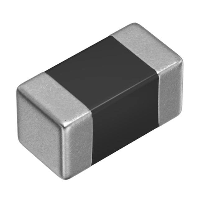
(1/3)
SMD Inductors(Coils)
For Signal Line(Multilayer, Magnetic Shielded)
Conformity to RoHS Directive
MLF Series MLF1005
Various kinds of digital equipment are becoming smaller with more
advanced functions. Therefore, parts used in such digital
equipment need to be small and thinner.
MLFI005 Series inductors were developed to meet these
demands. This series of inductors have 75% less mass than
conventional MLF1608 inductors and are magnetically sealed just
like conventional inductors, making high-density mounting
possible.
PRODUCT IDENTIFICATION
MLF 1005 DR10 K T
(1)
(2)
(3) (4) (5)
(1) Series name
(2) Dimensions L× W
1005
FEATURES
• 75% less mass than the MLF1608 series.
• Magnetically sealed configuration allowing for high-density
mounting.
• Does not contain lead and is compatible with lead-free
soldering.
• It is a product conforming to RoHS directive.
1.0× 0.5× 0.5
(3) Material code
(4) Inductance value
R10
1R0
0.1µH
1.0µH
(5) Inductance tolerance
APPLICATIONS
Signal processing modules such as mobile phones and tuners
K
±10%
(6) Packaging style
T
SPECIFICATIONS
Operating temperature range
Storage temperature range
–40 to +85°C
–40 to +85°C
RECOMMENDED SOLDERING CONDITION
REFLOW SOLDERING
10s max.
250 to 260˚C
Natural
cooling
230˚C
180˚C
150˚C
Preheating
60 to 120s
Soldering
30 to 60s
Time(s)
Taping [reel]
PACKAGING STYLE AND QUANTITIES
Packaging style
Taping
Quantity
10000 pieces/reel
HANDLING AND PRECAUTIONS
• Before soldering, be sure to preheat components.
The preheating temperature should be set so that the temperature difference between the solder temperature and product
temperature does not exceed 150°C.
• After mounting components onto the printed circuit board, do not
apply stress through board bending or mishandling.
• The inductance value may change due to magnetic saturation if
the current exceeds the rated maximum.
• Do not expose the inductors to stray magnetic fields.
• Avoid static electricity discharge during handling.
• When hand soldering, apply the soldering iron to the printed circuit board only. Temperature of the iron tip should not exceed
350°C. Soldering time should not exceed 3 seconds.
• Conformity to RoHS Directive: This means that, in conformity with EU Directive 2002/95/EC, lead, cadmium, mercury, hexavalent chromium, and specific
bromine-based flame retardants, PBB and PBDE, have not been used, except for exempted applications.
• Please contact our Sales office when your application are considered the following:
The device’s failure or malfunction may directly endanger human life (e.g. application for automobile/aircraft/medical/nuclear power devices, etc.)
• All specifications are subject to change without notice.
002-04 / 20090402 / e511_mlf1005.fm
�(2/3)
SHAPES AND DIMENSIONS/RECOMMENDED PC BOARD PATTERN
0.5±0.05
1.0±0.05
0.1min.
0.5
0.4
0.5
0.5
0.5±0.05
0.1min.
Dimensions in mm
Net weight : 1.2mg
ELECTRICAL CHARACTERISTICS
Part No.
Inductance
(µH)
Inductance
tolerance
MLF1005DR10K
MLF1005DR12K
MLF1005DR15K
MLF1005DR18K
MLF1005DR22K
MLF1005DR27K
MLF1005DR33K
MLF1005AR39K
MLF1005AR47K
MLF1005AR56K
MLF1005AR68K
MLF1005AR82K
MLF1005A1R0K
MLF1005A1R2K
MLF1005A1R5K
MLF1005A1R8K
MLF1005A2R2K
0.1
0.12
0.15
0.18
0.22
0.27
0.33
0.39
0.47
0.56
0.68
0.82
1.0
1.2
1.5
1.8
2.2
±10%
±10%
±10%
±10%
±10%
±10%
±10%
±10%
±10%
±10%
±10%
±10%
±10%
±10%
±10%
±10%
±10%
Test
frequency
L, Q (MHz)
25
25
25
25
25
25
25
10
10
10
10
10
10
10
10
10
10
Test
current
L, Q (mA)
1.0
1.0
1.0
1.0
1.0
1.0
1.0
1.0
1.0
1.0
1.0
1.0
1.0
1.0
1.0
1.0
1.0
Q min.
10
10
10
10
10
10
10
25
25
25
25
25
25
25
25
25
25
Self-resonant
frequency
(MHz)min.
450
400
350
320
290
260
230
210
190
170
150
130
120
110
100
90
80
DC resistance
(Ω)max.
Rated current
(mA)max.
0.60
0.70
0.80
0.90
1.10
1.30
1.50
0.60
0.65
0.70
0.80
0.90
1.00
1.10
1.30
1.55
1.80
25
25
25
25
25
25
25
10
10
10
10
10
10
10
10
10
10
・Test equipment(L, Q): Ag-4294A or equivalent
Test tool: Ag-16034G or equivalent
TYPICAL ELECTRICAL CHARACTERISTICS
INDUCTANCE vs. FREQUENCY CHARACTERISTICS
10
Inductance (µH)
2.2µH
1
1.0µH
0.33µH
0.1
0.01
0.1µH
1
10
100
Frequency (MHz)
1000
10000
Q vs. FREQUENCY CHARACTERISTICS
IMPEDANCE vs. FREQUENCY CHARACTERISTICS
60
10000
0.33µH
50
2.2µH
1000
Impedance (Ω)
40
Q
0.1µH
30
1.0µH
0.33µH
20
2.2µH
1.0µH
100
0.1µH
10
10
0
1
10
100
Frequency (MHz)
1000
10000
1
1
10
100
Frequency (MHz)
1000
10000
• All specifications are subject to change without notice.
002-04 / 20090402 / e511_mlf1005.fm
�(3/3)
PACKAGING STYLES
REEL DIMENSIONS
ø60min.
1.0
2.0±0.5
8.4 +2.0
–0.0
ø13±0.2
14.4max.
ø21±0.8
ø180±2.0
Dimensions in mm
Cavity
3.5±0.05
1.5 +0.1
–0.0
0.8max.
0.65±0.1
4.0±0.1
2.0±0.05
160min.
Taping
2.0±0.05
1.15±0.1
8.0±0.3
Sprocket hole
1.75±0.1
TAPE DIMENSIONS
200min.
Drawing direction
300min.
Dimensions in mm
• All specifications are subject to change without notice.
002-04 / 20090402 / e511_mlf1005.fm
�
很抱歉,暂时无法提供与“MLF1005DR12KT”相匹配的价格&库存,您可以联系我们找货
免费人工找货