Te m p e r a t u r e P r o t e c t i o n D e v i c e s
December 2021
Temperature protection device
Chip NTC thermistor
Automotive grade, for conductive glue
NTCSP series
NTCSP10
NTCSP16
JIS 1005 [EIA 0402]
JIS 1608 [EIA 0603]
�(2/12)
Temperature Protection Devices
REMINDERS FOR USING THESE PRODUCTS
Before using these products, be sure to request the delivery specifications.
SAFETY REMINDERS
Please pay sufficient attention to the warnings for safe designing when using this products.
Incorrect usage may cause smoke or fire.
REMINDERS
Please use them within the ranges of the ratings and performance provided in the catalog and delivery specifications upon confirming the environments where they are to be used and installed.
Do not use them outside the operating temperature range.
Do not use them with the ratings or maximum permissible power levels exceeded.
Do not quickly apply 5mW or more of load with the constant-voltage power supply as this may lead to staying in thermal runaway mode or the redshorting of chips.
Please be cautious of the applied voltage in thermistors as instruments may malfunction with the lowering of resistance due to self heating.
With instruments that consumers can touch the thermistors with their hands, please carefully warn them not to touch the thermistors.
Store them in locations where the temperature is 10°C to +40°C and the relative humidity is 75% or below, avoid environments where there are sudden changes in temperatures, direct sunlight, corrosive gas, grit, or dust, and keep them packed in a manner where no loading stress is applied in
order to avoid deterioration and damage.
(Please use within 6 months after delivery.)
If the storage period is exceeded, the surface of the terminal electrode may be oxidized or sulfided and the resistance value may shift.
When sealing thermistors, please do so upon first considering the type, quantity, hardening conditions, and adhesiveness of the sealing material and
confirming its reliability.
Avoid powerful vibrations, impact (such as by dropping), pressure, etc. on thermistors that exceed the prescribed levels.
Do not use them for long periods of time in environments with a relative humidity of over 85%. (this excludes cases where countermeasures have
been taken.)
Do not use them in the following environments. (this excludes cases where countermeasures have been taken.)
・Corrosive gases (Cl2, NH3, SOx, NOx, etc.)
・Environments with highly conductive substances (electrolytes, water, saltwater, etc.)
・Environments with acid, alkali, or organic solvents
・Dusty areas
When using an alumina substrate, do a reliability test beforehand certainly, and please confirm that it's no problem (Cracks don't occur to a product.)
Please observe the following precautions when attaching them to substrates as failure to do so may result in destruction or malfunction.
・Do not let the substrates get warped or twisted at any time during mounting.
・The landing size must be even on both the left and right sides.
・Do not use items that have been dropped or detached.
・The conductive paste is used in an appropriate amount.
Please use a substance such as resin that does not generate hydrogen (H2) when forming insulation film over chips.
The products listed on this specification sheet are intended for use in general electronic equipment (AV equipment, telecommunications equipment,
home appliances, amusement equipment, computer equipment, personal equipment, office equipment, measurement equipment, industrial robots)
under a normal operation and use condition.
The products are not designed or warranted to meet the requirements of the applications listed below, whose performance and/or quality require a
more stringent level of safety or reliability, or whose failure, malfunction or trouble could cause serious damage to society, person or property.
Please note that you cannot take responsibility for the damage caused by the use of this specification beyond the scope and conditions of the
applications listed below or this specification sheet.
If you plan to use this product beyond the scope and conditions of the applications listed below or this specification sheet, please consult us at
advance. We will discuss the contents of the warranty in accordance with your use.
(1) Aerospace/aviation equipment
(2) Transportation equipment (electric trains, ships, etc.)
(3) Medical equipment
(4) Power-generation control equipment
(5) Atomic energy-related equipment
(6) Seabed equipment
(7) Transportation control equipment
(8) Public information-processing equipment
(9) Military equipment
(10) Electric heating apparatus, burning equipment
(11) Disaster prevention/crime prevention equipment
(12) Safety equipment
(13) Other applications that are not considered general-purpose
applications
When designing your equipment even for general-purpose applications, you are kindly requested to take into consideration securing protection circuit/device or providing backup circuits in your equipment.
20211201 / tpd_automotive_ntc-thermistor_ntcsp_en.fm
�(3/12)
Temperature Protection Devices
Product compatible with RoHS directive
Corresponding to conductive glue
Chip NTC thermistor
Automotive grade, for conductive glue
Overview of the NTCSP series
CHARACTERISTICS OF NTC THERMISTORS
NTC(Negative Temperature Coefficient) thermistors are
manufactured from sintered metal oxides. Each thermistor
consists of a combination of two to four of the following materials:
manganese, nickel, cobalt and copper. NTC thermistors are
semiconductor resistors that exhibit decreasing resistance
characteristics with increasing temperature. TDK thermistors have
low thermal time constants which result in extremely high rates of
resistance change to accurately track the temperature.
Fig.1 R-T Curve : 10kohm@25°C
FEATURES OF NTCG SERIES
Conductive glue can mount.
The line-up corresponding to 150 °C.
AEC-Q200 compliant.
Fig.2 Internal structure of the multilayer chip Thermistors
Plated terminal type
Conductive epoxy type
1000
Resistance (kΩ)
100
Sn
Ni
Ag
AgPd
10
APPLICATIONS
For only conductive glue mounting, not for solder mounting.
ABS, transmission, engine sensors, etc.
1
0.1
–100
–50
0
50
100
Temperature (°C)
150
200
RoHS Directive Compliant Product: See the following for more details.https://product.tdk.com/info/en/environment/rohs/index.html
Please be sure to request delivery specifications that provide further details on the features and specifications of the products for proper and safe use.
Please note that the contents may change without any prior notice due to reasons such as upgrading.
20211201 / tpd_automotive_ntc-thermistor_ntcsp_en.fm
�(4/12)
Temperature Protection Devices
Product compatible with RoHS directive
Corresponding to conductive glue
Chip NTC thermistor
Automotive grade, for conductive glue
Overview of the NTCSP series
PART NUMBER CONSTRUCTION
NTC
SP
○○
3J
□
Series
name
Structural
classification
shapes and
dimensions
Code
(mm)
B
constant
B constant
tolerance
(%)
NTC
thermistor
SP
Corresponding to
conductive glue
10
1005
16
1608
F
±1
103
□
T
□□□
Nominal
resistance
Nominal
resistance
tolerance
(%)
Packaging
style
TDK internal code
F
T
Taping
1S
B
Bulk
1SX
()
103
473
104
B
10,000
(10k)
47,000
(47k)
100,000
(100k)
±1
150°C vehicle response
B constant: 25/85°C
150°C vehicle response
B constant: 25/50°C
constant
B constant(K)
2000 to 2050
2051 to 2100
2101 to 2150
2201 to 2250
2251 to 2300
2401 to 2450
2451 to 2500
2501 to 2550
2601 to 2650
2701 to 2750
2801 to 2850
2A
2B
2C
2E
2F
2J
2K
2L
2N
2Q
2S
3A
3B
3C
3E
3F
3J
3K
3L
3N
3Q
3S
3000 to 3050
3051 to 3100
3101 to 3150
3201 to 3250
3251 to 3300
3401 to 3450
3451 to 3500
3501 to 3550
3601 to 3650
3701 to 3750
3801 to 3850
4A
4B
4C
4E
4F
4J
4K
4L
4N
4Q
4S
4000 to 4050
4051 to 4100
4101 to 4150
4201 to 4250
4251 to 4300
4401 to 4450
4451 to 4500
4501 to 4550
4601 to 4650
4701 to 4750
4801 to 4850
B constant calculation formula
B=
InR1–InR2
(1/T1)–(1/T2)
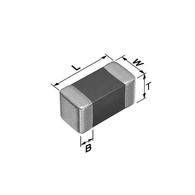
Shape symbol (JIS)
1005
1608
B: B constant (K)
T1:Arbitrary temperature (K)
T2:Arbitrary temperature different from T1 (K)
R1:Zero-load resistance value at temperature T1()
R2:Zero-load resistance value at temperature T2()
Each temperature is measured in absolute temperature. 0°C=273.15K
L
1.00±0.05
1.60±0.10
W
0.50±0.05
0.80±0.10
T
0.50±0.05
0.80±0.10
Dimensions in mm
B
0.1min
0.2min
COMPATIBLE WITH CONDUCTIVE GLUE
mm
1005
1608
Size
Maximum rated power (25°C)Asteris1 mW
125
125
Dissipation factors (25°C) 2
mW/°C | mW/K
1
1
1 Maximum rated power: Maximum power: at rated temperature (25°C), maximum power that can be applied continuously
2 Dissipation factors: powered that it is equivalent that be increased in self-heating by load power thermistor at 1°C temperature
Please be sure to request delivery specifications that provide further details on the features and specifications of the products for proper and safe use.
Please note that the contents may change without any prior notice due to reasons such as upgrading.
20211201 / tpd_automotive_ntc-thermistor_ntcsp_en.fm
�(5/12)
Temperature Protection Devices
Product compatible with RoHS directive
Corresponding to conductive glue
Chip NTC thermistor
Automotive grade, for conductive glue
NTCSP series 1005 type
SHAPE & DIMENSIONS
RECOMMENDED LAND PATTERN
0.5±0.05
0.5 to 0.7
1±0.05
0.35 to 0.45
0.6min.
0.35 to 0.45
0.5±0.05
0.1 min.
Electrode material
Internal:Pd
External:Ag/Pg
Dimensions in mm
COMPATIBLE WITH CONDUCTIVE GLUE (OPERATING TEMPERATURE RANGE:–55 to 150°C)
Part No.
Resistance
[25°C]
()
NTCSP103JF103FT1S
10,000
NTCSP104BF473FT1SX
47,000
100,000
NTCSP104KF104FT1S
Resistance
tolerance
B constant
[25/50°C]
(K)
B constant
[25/75°C]
(K)
B constant
[25/85°C]
(K)
B constant
[25/100°C]
(K)
B constant
tolerance
±1%
±1%
±1%
3380
4050
4419
3422
4098
4468
3435
4114
4485
3453
4137
4509
±1%
±1%
±1%
Permissible
operating
current
[25°C]
(mA)
0.31
0.14
0.10
Please be sure to request delivery specifications that provide further details on the features and specifications of the products for proper and safe use.
Please note that the contents may change without any prior notice due to reasons such as upgrading.
20211201 / tpd_automotive_ntc-thermistor_ntcsp_en.fm
�(6/12)
Temperature Protection Devices
Product compatible with RoHS directive
Corresponding to conductive glue
Chip NTC thermistor
Automotive grade, for conductive glue
NTCSP series 1608 type
SHAPE & DIMENSIONS
RECOMMENDED LAND PATTERN
0.8±0.1
1.1 to 1.3
1.6±0.1
0.6 to 0.8
0.9min.
0.6 to 0.8
0.8±0.1
0.2 min.
Electrode material
Internal:Pd
External:Ag/Pd
Dimensions in mm
COMPATIBLE WITH CONDUCTIVE GLUE (OPERATING TEMPERATURE RANGE:–55 to 150°C)
Part No.
Resistance
[25°C]
()
NTCSP163JF103FT1S
10,000
NTCSP164BF473FT1SX
47,000
100,000
NTCSP164KF104FT1S
Resistance
tolerance
B constant
[25/50°C]
(K)
B constant
[25/75°C]
(K)
B constant
[25/85°C]
(K)
B constant
[25/100°C]
(K)
B constant
tolerance
±1%
±1%
±1%
3380
4050
4419
3422
4098
4468
3435
4114
4485
3453
4137
4509
±1%
±1%
±1%
Permissible
operating
current
[25°C]
(mA)
0.31
0.14
0.10
Please be sure to request delivery specifications that provide further details on the features and specifications of the products for proper and safe use.
Please note that the contents may change without any prior notice due to reasons such as upgrading.
20211201 / tpd_automotive_ntc-thermistor_ntcsp_en.fm
�(7/12)
Temperature Protection Devices
Product compatible with RoHS directive
Corresponding to conductive glue
Chip NTC thermistor
Automotive grade, for conductive glue
NTCSP series RT table
R-T TABLE ACQUISITION PROCEDURE
1. Access the top page of the TDK chip NTC thermistor (protective device)
https://product.tdk.com/info/en/products/protection/temperature/chip-ntc-thermistor/index.html
2. Click [Search by Part No.]
https://product.tdk.com/en/search/protection/temperature/chip-ntc-thermistor/part_no/
3. Enter the product name you want in the RT table in the box and click the Search button.
( Example: NTCG103JF103FT1 )
Wildcard and Multiple Part number.
NTCG103JF103FT1
Question mark (?) and asterisk (*) can be used as wildcard characters.
Search
The question mark (?) matches any single character, and the asterisk (*)
matches any sequence of characters.
Enable the real time search
Enter only one part number per line. Up to 50 part numbers can be
searched simultaneously.
A part number search is normally performed using a prefix search. If you
wish to use a suffix search, enter an exclamation mark (!) at the end of
the Part No.
4. Click the displayed product name.
( Example: NTCG103JF103FT1 )
Catalog /
Check Data
Images
Sheet
Part No.
NTCG103JF103FT1
New
NTCG103JF103FT1S
Distributor
Inventory
Brand
Buy Now
TDK
Buy Now
TDK
Apps.
Feature
125°C
UL
150°C
AEC-Q200
5. Individual pages are displayed and click the RT table in the "Document" on the right side bar.
Documents
Catalog
RoHS Certificate
SVHC/REACH Certificate
Selection Guide
RT Sheet
6. You can download the csv file in the 1°C step of the RT table for the product.
Please be sure to request delivery specifications that provide further details on the features and specifications of the products for proper and safe use.
Please note that the contents may change without any prior notice due to reasons such as upgrading.
20211201 / tpd_automotive_ntc-thermistor_ntcsp_en.fm
�(8/12)
Temperature Protection Devices
Product compatible with RoHS directive
Corresponding to conductive glue
Chip NTC thermistor
Automotive grade, for conductive glue
Attention in the board design
BOARD DESIGN
Amount of conductive glue
When attached to NTC substrate thermistor, amount of conductive
glue has direct impact on NTC thermistor after mounting. Thus,
sufficient consideration is necessary.
Excessive amount of conductive glue during mounting can cause
electrical path formation under the chip (between the lands).
In addition, when the amount of conductive glue is excessive, the
terminal electrode sticking force is insufficient, causing chip falling
off, which may affect the reliability of the circuit. A typical example
of the amount of conductive glue is shown below.
Set of land dimensions
As the stress rises in the NTC thermistor owing to the increase in
silver, breakage and cracks will occur. Cause including crack, as
caution on board land design, configure the shape and dimensions
so that the amount of conductive glue is appropriate.
Excess adhesive forms a
conductive path under the
chip.
Conductive glue
overload
C
B
Shape symbol
1005
1608
Conductive glue
volume
A
Symbol
A
0.6min.
0.9min.
B
0.35 to 0.45
0.60 to 0.80
C
0.50 to 0.70
1.10 to 1.30
The sticking force is weak,
the connection is bad, and
there is a risk of falling off.
Conductive glue
deficit
Attention on the mounting
APPLICATION TO BOARD
Mounting head pressure
Under suction nozzle if dead point too, during implementation,
excessive force joins of NTC thermistor low, as cause causes of
crack, please use with reference to something about following.
1) The bottom dead center of the suction nozzle is set on the upper
surface of the substrate to adjust the excessive load to the
substrate.
2) Nozzle pressure at implementation is 1N−3N in static load,
please.
Cases to avoid
Recommended case
Crack
Single-sided
mounting
Support pin
Double-sided
mounting
Peeling
Crack
Support pin
Please be sure to request delivery specifications that provide further details on the features and specifications of the products for proper and safe use.
Please note that the contents may change without any prior notice due to reasons such as upgrading.
20211201 / tpd_automotive_ntc-thermistor_ntcsp_en.fm
�(9/12)
Temperature Protection Devices
Chip NTC thermistor
Product compatible with RoHS directive
Corresponding to conductive glue
Automotive grade, for conductive glue
Single-part component handling
(1) To drop impact, as there is possibility that breakage and crack is
entered, do not NTC thermistor that(1) NTC thermistor falls.
Crack
Floor
(2) At stacking storage after implementation and treatment of
substrate, corner of boards is regarded as NTC thermistor. Please
be careful, as there is the possibility that breakage and cracks will
occur on impact.
Crack
Board
Please be sure to request delivery specifications that provide further details on the features and specifications of the products for proper and safe use.
Please note that the contents may change without any prior notice due to reasons such as upgrading.
20211201 / tpd_automotive_ntc-thermistor_ntcsp_en.fm
�(10/12)
Temperature Protection Devices
Product compatible with RoHS directive
Corresponding to conductive glue
Chip NTC thermistor
Automotive grade, for conductive glue
Packaging style
REEL DIMENSIONS
PACKAGE QUANTITY, PRODUCT WEIGHT
Type
2.0±0.5
Individual weight
(mg)
1.3
5.0
ø60min.
NTCSP10
NTCSP16
Package quantity
(pieces/reel)
10,000
4,000
0.8
ø13±0.2
9.0max.
ø21±0.8
14.0max.
ø180±2.0
Dimensions in mm
2.0±0.05
4.0±0.1
A
8.0±0.3
B
3.5±0.05
1.5 +0.1
0
1.75±0.1
TAPE DIMENSIONS
T
P1
Dimensions in mm
Type
1005
1608
A
0.65+0.05/-0.1
1.1±0.2
160min.
Drawing direction
Taping
B
1.15+0.05/-0.1
1.9±0.2
P1
2±0.05
4.0±0.1
T
0.65max.
1.1max.
200min.
200min.
Dimensions in mm
Please be sure to request delivery specifications that provide further details on the features and specifications of the products for proper and safe use.
Please note that the contents may change without any prior notice due to reasons such as upgrading.
20211201 / tpd_automotive_ntc-thermistor_ntcsp_en.fm
�(11/12)
Temperature Protection Devices
Chip NTC thermistor
Product compatible with RoHS directive
Corresponding to conductive glue
Automotive grade, for conductive glue
Description and definition of terms
INITIAL RESISTANCE
Thermistor resistance is a function of absolute temperature as indicated by the following relationship:
1
1 ............................................................ (1)
–
R=R0 • expB
T
T0
(
)
Here R0, R(k) are the respective resistance values when the surrounding temperature is T0, T(K). B is the thermistor constant(B constant below).
B CONSTANT
The B constant is found from the following equation:
B=
2.3026(logR–logR0)
1 – 1
T T0
....................................................... (2)
This B characteristic is indicated by the slope of the linear plot of log R-1/T inverse absolute temperature.
The B constant value is generally in the vicinity of 2500K to 5000K. B constant values of 3000K to 4000K are frequently used for measurements.
Resistance-temperature characteristics (Fig.1)
450 400 350 300
Temperature(˚C)
250
200
150
100
100
20kΩ /200˚C
Resistance (kΩ)
10
3.3kΩ/100˚C
1
1.4
1.6
1.8
2
2.2
1 × 10 3 (K)
T
2.4
2.6
2.8
3
TEMPERATURE COEFFICIENT
The relationship between temperature coefficient and B becomes:
B
1 dR
= •
= – 2 100(%/°C) ............................................. (3)
T
R dT
The negative sign of the temperature coefficient indicates that the temperature coefficient decreases as both thermistor resistance and
temperature rise. If B is taken as 3400K, the temperature coefficient found at 20°C (293.15K) becomes –4%/°C.
HEAT DISSIPATION COEFFICIENT
Temperature rises due to thermal energy formed as electrical current flows through the thermistor. The thermistor temperature T0 is then
related to the surrounding temperature Ta and the electrical input W:
W=k(T0–Ta)=V•I(mW) ............................................................ (4)
k=
W
(mW/°C) .............................................................. (5)
T0 –Ta
This k value is the heat dissipation coefficient, which represents the additional electrical power (mW/°C) needed to raise the thermistor
temperature by 1°C. This heat dissipation coefficient varies with changes in the measurement and environmental conditions. When a
thermistor is used for temperature measurement, it is naturally important to lower the applied electrical current as much as possible in
order to reduce measurement error resulting from self heating.
Please be sure to request delivery specifications that provide further details on the features and specifications of the products for proper and safe use.
Please note that the contents may change without any prior notice due to reasons such as upgrading.
20211201 / tpd_automotive_ntc-thermistor_ntcsp_en.fm
�(12/12)
Temperature Protection Devices
Product compatible with RoHS directive
Corresponding to conductive glue
Chip NTC thermistor
Automotive grade, for conductive glue
Description and definition of terms
VOLTAGE - CURRENT CHARACTERISTIC
The voltage - current characteristic indicates the drop in voltage as electrical current through the thermistor is gradually increased.
Voltage-current characteristics (Fig.2)
100
5
4
10
3
Voltage (V)
2
1
1
0.1
Ta=25˚C (in still air)
No.1 5kΩ
2 10kΩ
3 20kΩ
4 50kΩ
5 100kΩ
10
100
1
Current (mA)
HEATING TIME CONSTANT
The time period required to heat up a thermistor from a certain temperature T0 over a target temperature rise is called the heating time
constant. Various types of heating time constants are indicated by the symbols shown in Table 1 as determined by the percent change
from T0 toward the target temperature. The standard change is typically taken to be 63.2%.
Thermal time constants (Fig.3)
70
Table 1 Heating time constant and temperature change ratio
Heating
Code
2
3
4
5
6
7
Th
40
Tc
30
20
(T0 –Ta)
×0.368
Temperature (˚C)
50
T0
(T0 –Ta)
×0.632
60
Room temperature Ta
Cooling
Rate of change (%) for T0 -Ta
63.2
86.5
95.0
98.2
99.4
99.8
99.9
10
0
τ
2τ
3τ
4τ
5τ
6τ
7τ
PERMISSIBLE OPERATING CURRENT
This is the maximum load current limit below 1°C temperature rise due to thermistor self-heating.
It's possible to express it in the following system.
Maximum allowed current [mA] = √(Heat dissipation constant[mW/°C] ÷ Resistance[]
Please be sure to request delivery specifications that provide further details on the features and specifications of the products for proper and safe use.
Please note that the contents may change without any prior notice due to reasons such as upgrading.
20211201 / tpd_automotive_ntc-thermistor_ntcsp_en.fm
�


 工商网监
湘ICP备2023018690号
工商网监
湘ICP备2023018690号
