(1/3)
SMD Inductors(Coils) For Power Line(Wound, Magnetic Shielded)
VLF-MT Series VLF302512MT
With the VLF302512MT Series, a DC to DC converter with topclass voltage conversion efficiency for similar size products was achieved by optimizing the magnetic material and configuration. These products are optimal for use as choke coils in switching power supplies such as those in mobile devices requiring spacesaving design. FEATURES • Miniature size Mount area: 3.0×2.5mm Low profile: 1.2mm max. height • Generic use for portable DC to DC converter line. • High magnetic shield construction should actualize high resolution for EMC protection. • The products contain no lead and also support lead-free soldering. • The products is halogen-free. • It is a product conforming to RoHS directive. APPLICATIONS Smartphones, cellular phones, DSCs, DVCs, HDDs, LCD displays, compact power supply modules, etc. SHAPES AND DIMENSIONS
2.5± 0.2
Conformity to RoHS Directive
PRODUCT IDENTIFICATION VLF 302512M T - 1R0 N (1) (2) (3) (4) (5) (1) Series name (2) Dimensions L×W×H mm max. (3) Packaging style
T Taping (Embossed carrier tape)
(4) Inductance value
1R0 100 1.0µH 10µH
(5) Inductance tolerance
M N ±20% ±30%
PACKAGING STYLE AND QUANTITIES
Packaging style Taping Quantity 2000 pieces/reel
HANDLING AND PRECAUTIONS • Before soldering, be sure to preheat components. The preheating temperature should be set so that the temperature difference between the solder temperature and product temperature does not exceed 150°C. • When hand soldering, apply the soldering iron to the printed circuit board only. Temperature of the iron tip should not exceed 350°C. Soldering time should not exceed 3 seconds.
Weight: 0.033g Dimensions in mm
3.0±0.2
1.2max.
(0.7) (0.8)
(0.7)
(1.0)
RECOMMENDED SOLDERING CONDITION REFLOW SOLDERING
RECOMMENDED PC BOARD PATTERN
1.45 10s max. 250 to 260˚C 230˚C Natural cooling
0.9 0.8
0.9 Dimensions in mm
CIRCUIT DIAGRAM
180˚C 150˚C Preheating 60 to 120s Time(s) Soldering 30 to 60s
• Conformity to RoHS Directive: This means that, in conformity with EU Directive 2002/95/EC, lead, cadmium, mercury, hexavalent chromium, and specific bromine-based flame retardants, PBB and PBDE, have not been used, except for exempted applications. • Please contact our Sales office when your application are considered the following: The device’s failure or malfunction may directly endanger human life (e.g. application for automobile/aircraft/medical/nuclear power devices, etc.)
• All specifications are subject to change without notice. 002-02 / 20101028 / e531_vlf302512mt.fm
�(2/3)
ELECTRICAL CHARACTERISTICS
DC resistance(Ω ) Part No. VLF302512MT-1R0N VLF302512MT-1R5N VLF302512MT-2R2M VLF302512MT-3R3M VLF302512MT-4R7M VLF302512MT-6R8M VLF302512MT-100M VLF302512MT-150M VLF302512MT-220M
∗
Inductance (µH) 1.0 1.5 2.2 3.3 4.7 6.8 10 15 22
Inductance tolerance(%) ±30 ±30 ±20 ±20 ±20 ±20 ±20 ±20 ±20
Test frequency (MHz) 1.0 1.0 1.0 1.0 1.0 1.0 1.0 1.0 1.0
max. 0.037 0.044 0.066 0.108 0.136 0.194 0.299 0.448 0.700
typ. 0.031 0.037 0.055 0.090 0.113 0.162 0.249 0.373 0.583
Rated current∗(A) Based on inductance change Idc1 max. typ. 1.91 2.12 1.67 1.85 1.26 1.40 1.08 1.20 0.97 1.08 0.78 0.84 0.62 0.69 0.51 0.57 0.43 0.47
Based on temperature rise Idc2 typ. 2.77 2.54 1.95 1.63 1.42 1.21 0.95 0.80 0.64
Rated current: Value obtained when current flows and the temperature has risen to 40°C or when DC current flows and the nominal value of inductance has fallen by 30%, whichever is smaller. • Operating temperature range: –40 to +105°C (Including self-temperature rise)
TYPICAL ELECTRICAL CHARACTERISTICS INDUCTANCE vs. DC SUPERPOSITION CHARACTERISTICS VLF302512MT-1R0N
1.2 1.0 Inductance(µH) 0.8 0.6 0.4 0.2 0.0
VLF302512MT-1R5N
1.5 Inductance(µH)
1.0
0.5
0.0 0 0.5 1 1.5 DC current (A) 2 2.5
0
0.5
1 DC current (A)
1.5
2
VLF302512MT-2R2M
3.0 2.5 Inductance(µH)
VLF302512MT-3R3M
3.5 3.0 Inductance(µH) 2.5 2.0 1.5 1.0 0.5
2.0 1.5 1.0 0.5 0.0 0 0.5 DC current (A) 1 1.5
0.0
0
0.5 DC current (A)
1
VLF302512MT-4R7M
5.0 Inductance(µH)
VLF302512MT-6R8M
7.0 6.0 Inductance(µH) 5.0 4.0 3.0 2.0 1.0
4.0 3.0 2.0 1.0 0.0 0 0.2 0.4 0.6 0.8 DC current (A) 1 1.2
0.0
0
0.2
0.4 0.6 DC current (A)
0.8
1
• All specifications are subject to change without notice. 002-02 / 20101028 / e531_vlf302512mt.fm
�(3/3)
TYPICAL ELECTRICAL CHARACTERISTICS INDUCTANCE vs. DC SUPERPOSITION CHARACTERISTICS VLF302512MT-100M
12 10 Inductance(µH) 8 6 4 2 0 0 0.2 0.4 DC current (A) 0.6 0.8
VLF302512MT-150M
15 Inductance(µH)
10
5
0
0
0.2
0.4 DC current (A)
0.6
VLF302512MT-220M
25
TEST CIRCUIT
A C=20,000µF L=0.1H Sample 1
Inductance(µH)
20 15 10 5 0 0 0.1 0.2 0.3 DC current (A) 0.4 0.5
2
1: LCR meter 4285A f=1MHz 2: DC constant current source
PACKAGING STYLES REEL DIMENSIONS
+0 ø180 –3
TAPE DIMENSIONS
øD0 P2 P0 P1 E K
ø21± 0.8 ø13± 0.2 2.0± 0.5
F
W
øD1
4-R3
t Cover type
ø60 –0
+1
2-R2
A0
2-R1
H
Dimensions in mm
9.0± 0.3 ・The taping reel dimensions and reusable reel are compliant with EIAJ ET-7200. 13± 1.4 Dimensions in mm
A0 2.8typ. P1 4.00± 0.1 K 1.35±0.1
B0 3.3typ. P2 2.00±0.05 øD1 1.2±0.2
W 8.00± 0.2 H 0.05 to 0.35 t 0.25±0.05
F 3.50± 0.1 P0 4.0±0.1 R1 to R3 0.3max.
E 1.75± 0.1 øD0 1.5+0.1/–0
θ
5° typ.
• All specifications are subject to change without notice. 002-02 / 20101028 / e531_vlf302512mt.fm
B0
θ
�
很抱歉,暂时无法提供与“VLF302512MT-1R5N”相匹配的价格&库存,您可以联系我们找货
免费人工找货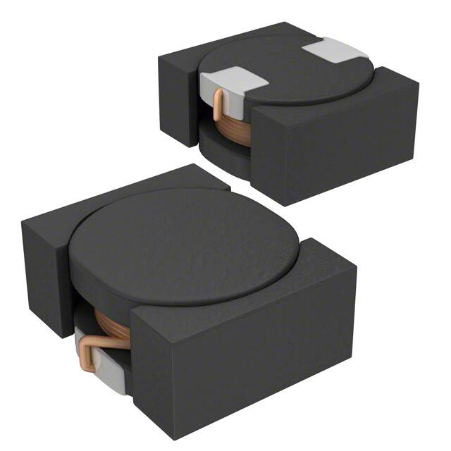


 工商网监
湘ICP备2023018690号
工商网监
湘ICP备2023018690号
