(1/2)
SMD Inductors(Coils)
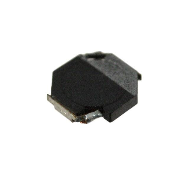
For Power Line(Wound, Magnetic Shielded)
Conformity to RoHS Directive
VLF Series VLF4012S
3.6±0.2
SHAPES AND DIMENSIONS
4R7
3.8±0.2
1.2max.
Dimensions in mm
RECOMMENDED PC BOARD PATTERN
1.3
FEATURES
• Miniature size
Mount area: 3.6× 3.8mm
Height: 1.2mm max.
• Generic use for portable DC to DC converter line.
• High magnetic shield construction should actualize high
resolution for EMC protection.
• Available for automatic mounting in tape and real package.
• The products do not contain lead and support lead-free
soldering.
2.9
APPLICATIONS
DVCs, DSCs, PDAs, LCD displays, cellular phones, HDDs, etc.
4.7
Dimensions in mm
ELECTRICAL CHARACTERISTICS
Part No.
Inductance
(µH)
Inductance
tolerance(%)
Test frequency
(MHz)
VLF4012ST-1R0N1R9
VLF4012ST-2R2M1R3
VLF4012ST-3R3M1R1
VLF4012ST-4R7M1R0
VLF4012ST-6R8MR80
VLF4012ST-100MR65
1
2.2
3.3
4.7
6.8
10
±30
±20
±20
±20
±20
±20
1
1
1
1
1
1
DC resistance(Ω)
max.
typ.
0.054
0.12
0.16
0.19
0.32
0.49
0.045
0.097
0.13
0.16
0.27
0.41
Rated current(A)∗
Based on inductance
change max.
2.7
1.7
1.5
1.4
1
0.9
Based on temperature
rise typ.
1.9
1.3
1.1
1
0.8
0.65
∗
Rated current: Value obtained when current flows and the temperature has risen to 40°C or when DC current flows and the nominal value of inductance
has fallen by 30%, whichever is smaller.
• Operating temperature range: –40 to +105°C (Including self-temperature rise)
VLF4012ST-2R2M1R3
1.2
2.5
1.0
2.0
Inductance(µH)
Inductance(µH)
TYPICAL ELECTRICAL CHARACTERISTICS
INDUCTANCE vs. DC SUPERPOSITION CHARACTERISTICS
VLF4012ST-1R0N1R9
0.8
0.6
0.4
1.0
0.5
0.2
0.0
0.0
1.5
0.5
1.0
1.5
2.0
DC current (A)
2.5
3.0
3.5
0.0
0.0 0.2 0.4 0.6 0.8 1.0 1.2 1.4 1.6 1.8 2.0 2.2
DC current (A)
• Conformity to RoHS Directive: This means that, in conformity with EU Directive 2002/95/EC, lead, cadmium, mercury, hexavalent chromium, and specific
bromine-based flame retardants, PBB and PBDE, have not been used, except for exempted applications.
• All specifications are subject to change without notice.
001-01 / 20070911 / e531_vlf4012s.fm
�(2/2)
VLF4012ST-4R7M1R0
4.0
6
3.5
5
3.0
Inductance(µH)
Inductance(µH)
TYPICAL ELECTRICAL CHARACTERISTICS
INDUCTANCE vs. DC SUPERPOSITION CHARACTERISTICS
VLF4012ST-3R3M1R1
2.5
2.0
1.5
1.0
3
2
1
0.5
0.0
0.0
0.2
0.4
0.6
0.8 1.0 1.2
DC current (A)
1.4
1.6
0
0.0
1.8
VLF4012ST-6R8MR80
0.2
0.4
0.6
0.8
1.0
DC current (A)
1.2
1.4
1.6
VLF4012ST-100MR65
12
8
10
Inductance(µH)
7
Inductance(µH)
4
6
5
4
3
2
8
6
4
2
1
0
0.0
0.2
0.4
0.6
0.8
DC current (A)
1.0
1.2
1.4
0
0.0
0.2
0.4
0.6
0.8
DC current (A)
1.0
1.2
TEST CIRCUIT
C=20,000µF
A
2
L=0.1H
Sample
1
1: LCR meter 4285A f=1MHz
2: DC constant current
• All specifications are subject to change without notice.
001-01 / 20070911 / e531_vlf4012s.fm
�
很抱歉,暂时无法提供与“VLF4012ST-4R7M1R0”相匹配的价格&库存,您可以联系我们找货
免费人工找货