I
N
D
U
C
T
O
R
S
November 2013
Inductors for Power Circuits
Wound Ferrite
VLMseries
VLM10555-2H
VLM10555-3H
VLM13580-D1
(For automobiles)
�(2/17)
I
N
D
U
C
T
O
R
S
REMINDERS FOR USING THESE PRODUCTS
Before using these products, be sure to request the delivery specifications.
SAFETY REMINDERS
Please pay sufficient attention to the warnings for safe designing when using these products.
REMINDERS
The storage period is less than 6 months. Be sure to follow the storage conditions (Temperature: 5 to 30°C, Humidity: 10 to 75% RH or
less).
If the storage period elapses, the soldering of the terminal electrodes may deteriorate.
Do not use or store in locations where there are conditions such as gas corrosion (salt, acid, alkali, etc.).
Before soldering, be sure to preheat components.
The preheating temperature should be set so that the temperature difference between the solder temperature and chip temperature
does not exceed 150°C.
Soldering corrections after mounting should be within the range of the conditions determined in the specifications.
If overheated, a short circuit, performance deterioration, or lifespan shortening may occur.
When embedding a printed circuit board where a chip is mounted to a set, be sure that residual stress is not given to the chip due to
the overall distortion of the printed circuit board and partial distortion such as at screw tightening portions.
Self heating (temperature increase) occurs when the power is turned ON, so the tolerance should be sufficient for the set thermal
design.
Carefully lay out the coil for the circuit board design of the non-magnetic shield type.
A malfunction may occur due to magnetic interference.
Use a wrist band to discharge static electricity in your body through the grounding wire.
Do not expose the products to magnets or magnetic fields.
Do not use for a purpose outside of the contents regulated in the delivery specifications.
The products listed on this catalog are intended for use in general electronic equipment (AV equipment, telecommunications
equipment, home appliances, amusement equipment, computer equipment, personal equipment, office equipment, measurement
equipment, industrial robots) under a normal operation and use condition.
The products are not designed or warranted to meet the requirements of the applications listed below, whose performance and/or
quality require a more stringent level of safety or reliability, or whose failure, malfunction or trouble could cause serious damage to
society, person or property.
If you intend to use the products in the applications listed below or if you have special requirements exceeding the range or conditions
set forth in the each catalog, please contact us.
(1) Aerospace/Aviation equipment
(2) Transportation equipment (electric trains, ships, etc.)
(3) Medical equipment
(4) Power-generation control equipment
(5) Atomic energy-related equipment
(6) Seabed equipment
(7) Transportation control equipment
(8) Public information-processing equipment
(9) Military equipment
(10) Electric heating apparatus, burning equipment
(11) Disaster prevention/crime prevention equipment
(12) Safety equipment
(13) Other applications that are not considered general-purpose
applications
When designing your equipment even for general-purpose applications, you are kindly requested to take into consideration securing
protection circuit/device or providing backup circuits in your equipment.
001-01 / 20131101 / inductor_automotive_power_vlm_en.fm
�(3/17)
I
N
D
U
C
T
O
R
S
Inductors for Power Circuits
Product compatible with RoHS directive
Compatible with lead-free solders
AEC-Q200
Wound Ferrite
Overview of the VLM Series
FEATURES
Low Rdc design using a rectangular wire.
Design with low core loss, large current capability design Mn-Zn core, and compatible with low loss and high current.
Compatible with vehicle-related equipment.
APPLICATION
Equipment used for automobiles (ECM, HID, EPS, etc.)
Vehicle accessory equipment (Vehicle AV equipment, car navigation, automobile air conditioners, etc.)
PART NUMBER CONSTRUCTION
VLM
Series name
10555
L×W×H Dimensions
(mm)
10555 10.5×10.6×5.4
13580 13.5×12.2×7.8
T
Packaging style
T
Taping
-
1R8
M
8R8
Inductance
(μH)
1R8
1.8
100
10
Inductance
tolerance
M
±20%
Rated current
(A)
8R8
8.8
100
10
-
2H
Internal code
OPERATING TEMPERATURE RANGE, PACKAGE QUANTITY, PRODUCT WEIGHT
Temperature range
Package quantity
Operating
Storage
temperature�
temperature��
(pieces/reel)
(°C)
(°C)
VLM10555-2H
–40 to +125
–40 to +125
500
VLM10555-3H
–40 to +125
–40 to +125
500
VLM13580-D1
–40 to +150
–40 to +150
400
��Operating temperature range includes self-temperature rise.
���The Storage temperature range is for after the circuit board is mounted.
Type
Individual weight
(g)
1.7
1.7
3.9
RoHS Directive Compliant Product: See the following for more details related to RoHS Directive compliant products. http://www.tdk.co.jp/rohs/
• All specifications are subject to change without notice.
001-01 / 20131101 / inductor_automotive_power_vlm_en.fm
�(4/17)
I
N
D
U
C
T
O
R
S
Overview of the VLM Series
RECOMMENDED REFLOW PROFILE
Preheating
Soldering
Natural
cooling
Peak
T: Temperature
T4
T3
T2
T3
t3
T1
t1
t2
t: Time
Preheating
Temp.
T1
T2
150°C
180°C
Time
t1
60 to 120s
Soldering
Temp.
Time
T3
t2
230°C
30s
Peak
Temp.
T4
250°C
Time
t3
5s
• All specifications are subject to change without notice.
001-01 / 20131101 / inductor_automotive_power_vlm_en.fm
�(5/17)
I
N
D
U
C
T
O
R
S
VLM series
VLM10555-2H Type
SHAPE & DIMENSIONS
5.4±0.2
1.3±0.1
1.2±0.1
1.3±0.2
1R8M
10.6±0.2
2.2±0.2
1.3±0.2
10.5max.
Dimensions in mm
2.6
3.4
1.8
2.6
RECOMMENDED LAND PATTERN
3.0
6.1
1.9
Dimensions in mm
• All specifications are subject to change without notice.
001-01 / 20131101 / inductor_automotive_power_vlm_en.fm
�(6/17)
I
N
D
U
C
T
O
R
S
VLM series VLM10555-2H Type
ELECTRICAL CHARACTERISTICS
CHARACTERISTICS SPECIFICATION TABLE
L
(μH)
1.8
2.5
3.3
4.3
��
Tolerance
±20%
±20%
±20%
±20%
Measuring
frequency
(kHz)
100
100
100
100
DC resistance
(m� )
5.6
6.7
8.3
8.3
(%)
±15
±15
±15
±15
Rated current(A)�
max.
Idc1
18
15
12
9
typ.
Idc2
8.8
8
7.2
7.2
Part No.
VLM10555T-1R8M8R8-2H
VLM10555T-2R5M8R0-2H
VLM10555T-3R3M7R2-2H
VLM10555T-4R3M7R2-2H
Rated current: smaller value of either Idc1 or Idc2.
Idc1: When based on the inductance change rate (25% below the initial value)
Idc2: When based on the temperature increase (Temperature increase of 40°C by self heating)
○ Measurement equipment
Measurement item
Product No.
Manufacturer
L
4194A
Agilent Technologies
DC resistance
3220
HIOKI
Rated current Idc1
3260B+3265B
Wayne Kerr Electronics
* Equivalent measurement equipment may be used.
• All specifications are subject to change without notice.
001-01 / 20131101 / inductor_automotive_power_vlm_en.fm
�(7/17)
I
N
D
U
C
T
O
R
S
VLM series VLM10555-2H Type
ELECTRICAL CHARACTERISTICS
L FREQUENCY CHARACTERISTICS GRAPH
6
5
Inductance(μH)
4 4R3M
3R3M
3
2R5M
2
1R8M
1
0
10
100
1000
Frequency(kHz)
10000
100000
○ Measurement equipment
Product No.
Manufacturer
4294A
Agilent Technologies
* Equivalent measurement equipment may be used.
• All specifications are subject to change without notice.
001-01 / 20131101 / inductor_automotive_power_vlm_en.fm
�(8/17)
I
N
D
U
C
T
O
R
S
VLM series VLM10555-2H Type
ELECTRICAL CHARACTERISTICS
INDUCTANCE VS. DC BIAS CHARACTERISTICS GRAPH
8
7
Inductance(μH)
6
5
4R3M
4
3R3M
3
2R5M
2
1R8M
1
0
0
5
10
DC current(A)
15
20
○ Measurement equipment
Product No.
Manufacturer
3260B+3265B
Wayne Kerr Electronics
* Equivalent measurement equipment may be used.
• All specifications are subject to change without notice.
001-01 / 20131101 / inductor_automotive_power_vlm_en.fm
�(9/17)
I
N
D
U
C
T
O
R
S
VLM series
VLM10555-3H Type
SHAPE & DIMENSIONS
5.4±0.2
1.3±0.1
1.8±0.2
1.2±0.1
R45M
10.6±0.2
2.2±0.2
1.8±0.2
10.5max.
Dimensions in mm
2.6
3.4
1.8
2.6
RECOMMENDED LAND PATTERN
3.0
6.1
1.9
Dimensions in mm
• All specifications are subject to change without notice.
001-01 / 20131101 / inductor_automotive_power_vlm_en.fm
�(10/17)
I
N
D
U
C
T
O
R
S
VLM series VLM10555-3H Type
ELECTRICAL CHARACTERISTICS
CHARACTERISTICS SPECIFICATION TABLE
L
(nH)
330
450
560
700
1200
��
Tolerance
±20%
±20%
±20%
±20%
±20%
Measuring
frequency
(kHz)
100
100
100
100
100
DC resistance
(m� )
max.
typ.
1.2
0.95
2.6
2.2
2.5
2.1
2.5
2.1
3.2
2.7
Rated current* (A)
max.
typ.
Idc1
Idc2
34
18
40
11
34
12
26
12
18
10
Part No.
VLM10555T-R33M180-3H
VLM10555T-R45M110-3H
VLM10555T-R56M120-3H
VLM10555T-R70M120-3H
VLM10555T-1R2M100-3H
Rated current: smaller value of either Idc1 or Idc2.
Idc1: When based on the inductance change rate (25% below the initial value)
Idc2: When based on the temperature increase (Temperature increase of 40°C by self heating)
○ Measurement equipment
Measurement item
Product No.
L
4194A
DC resistance
3220
Rated current Idc1
3260B+3265B
* Equivalent measurement equipment may be used.
Manufacturer
Agilent Technologies
HIOKI
Wayne Kerr Electronics
• All specifications are subject to change without notice.
001-01 / 20131101 / inductor_automotive_power_vlm_en.fm
�(11/17)
I
N
D
U
C
T
O
R
S
VLM series VLM10555-3H Type
ELECTRICAL CHARACTERISTICS
L FREQUENCY CHARACTERISTICS GRAPH
10000
R56M
R45M
1R2M
Inductance(nH)
1000
R70M
R33M
100
10
1
10
100
1000
Frequency(kHz)
10000
100000
○ Measurement equipment
Product No.
Manufacturer
4294A
Agilent Technologies
* Equivalent measurement equipment may be used.
• All specifications are subject to change without notice.
001-01 / 20131101 / inductor_automotive_power_vlm_en.fm
�(12/17)
I
N
D
U
C
T
O
R
S
VLM series VLM10555-3H Type
ELECTRICAL CHARACTERISTICS
INDUCTANCE VS. DC BIAS CHARACTERISTICS GRAPH
2000
1800
1600
Inductance(nH)
1400
1R2M
1200
1000
800
R70M
600
R56M
R45M
400
R33M
200
0
0
5
10
15
20
25
DC current(A)
30
35
40
45
50
○ Measurement equipment
Product No.
Manufacturer
3260B+3265B
Wayne Kerr Electronics
* Equivalent measurement equipment may be used.
• All specifications are subject to change without notice.
001-01 / 20131101 / inductor_automotive_power_vlm_en.fm
�(13/17)
I
N
D
U
C
T
O
R
S
VLM series
VLM13580-D1 Type
SHAPE & DIMENSIONS
1.9±0.2
2R2
13.5±0.5
2.6±0.4
2.8±0.2
2.5±0.1
7.8±0.5
1.9±0.2
12.2±0.5
Dimensions in mm
2.45
3
5.4
2.45
RECOMMENDED LAND PATTERN
3.4
6
3.3
Dimensions in mm
• All specifications are subject to change without notice.
001-01 / 20131101 / inductor_automotive_power_vlm_en.fm
�(14/17)
I
N
D
U
C
T
O
R
S
VLM series VLM13580-D1 Type
ELECTRICAL CHARACTERISTICS
CHARACTERISTICS SPECIFICATION TABLE
L
(μH)
Tolerance(%)
Measuring
frequency
(kHz)
0.82
1.5
2.2
3.3
±20
±20
±20
±20
100
100
100
100
��
DC resistance
(m� )
Rated current(A)�
max.
max.
typ.
Idc1
2
2.5
3.9
4.5
1.7
2.1
3.3
3.8
36
26
20
18
typ.
Idc2
Self heating 20°C
12.6
11.3
10.5
8.4
Part No.
VLM13580T-R82M-D1
VLM13580T-1R5M-D1
VLM13580T-2R2M-D1
VLM13580T-3R3M-D1
Rated current: smaller value of either Idc1 or Idc2.
Idc1: When based on the inductance change rate (30% below the nominal value)
Idc2: When based on the temperature increase (Temperature increase of 40°C by self heating)
○ Measurement equipment
Measurement item
Product No.
L
4194A
DC resistance
VP-2941A
Rated current Idc1
4284A+42841A+42842C
* Equivalent measurement equipment may be used.
Manufacturer
Agilent Technologies
Panasonic
Agilent Technologies
• All specifications are subject to change without notice.
001-01 / 20131101 / inductor_automotive_power_vlm_en.fm
�(15/17)
I
N
D
U
C
T
O
R
S
VLM series VLM13580-D1 Type
ELECTRICAL CHARACTERISTICS
L FREQUENCY CHARACTERISTICS GRAPH
5000
4000
Inductance(nH)
3R3M
3000
2R2M
2000
1R5M
1000 R82M
0
10
100
1000
Frequency(kHz)
10000
100000
○ Measurement equipment
Product No.
Manufacturer
4294A
Agilent Technologies
* Equivalent measurement equipment may be used.
• All specifications are subject to change without notice.
001-01 / 20131101 / inductor_automotive_power_vlm_en.fm
�(16/17)
I
N
D
U
C
T
O
R
S
VLM series VLM13580-D1 Type
ELECTRICAL CHARACTERISTICS
INDUCTANCE VS. DC BIAS CHARACTERISTICS GRAPH
6000
5000
Inductance(nH)
4000
3000
3R3M
2000
2R2M
1R5M
1000
R82M
0
0
5
10
15
20
DC current(A)
25
30
35
40
○ Measurement equipment
Product No.
Manufacturer
4284A+42841A+42842C
Agilent Technologies
* Equivalent measurement equipment may be used.
• All specifications are subject to change without notice.
001-01 / 20131101 / inductor_automotive_power_vlm_en.fm
�(17/17)
I
N
D
U
C
T
O
R
S
VLM series
Packaging Style
REEL DIMENSIONS
2.0±0.5
E
Type
VLM10555-2H
VLM10555-3H
VLM13580-D1
A
ø330
ø330
ø330
W1
25.5
25.5
25.5
W2
30.4
30.4
30.4
N
ø100
ø100
ø100
E
2
2
2
N
* These values are typical values.
(1.0)
ø13.0±0.5
W1
ø21.0±0.8
W2
A
Dimensions in mm
TAPE DIMENSIONS
P2
P0
K
P1
t
A
Type
VLM10555-2H
VLM10555-3H
VLM13580-D1
A
11.5
11.5
13.5
B
11.5
11.5
13.5
B
W
F
E
øD0
øD0
1.5+0.1/-0
1.5+0.1/-0
1.5+0.1/-0
Dimensions in mm
E
F
P0
P1
P2
W
1.75±0.1 11.5±0.1 4.0±0.1 16.0±0.1 2.0±0.1 24.0±0.3
1.75±0.1 11.5±0.1 4.0±0.1 16.0±0.1 2.0±0.1 24.0±0.3
1.75±0.1 11.5±0.1 4.0±0.1 16.0±0.1 2.0±0.1 24.0±0.3
K
6.2
6.2
8.3
t
0.4
0.4
0.5
• All specifications are subject to change without notice.
001-01 / 20131101 / inductor_automotive_power_vlm_en.fm
�
很抱歉,暂时无法提供与“VLM13580T-2R2M-D1”相匹配的价格&库存,您可以联系我们找货
免费人工找货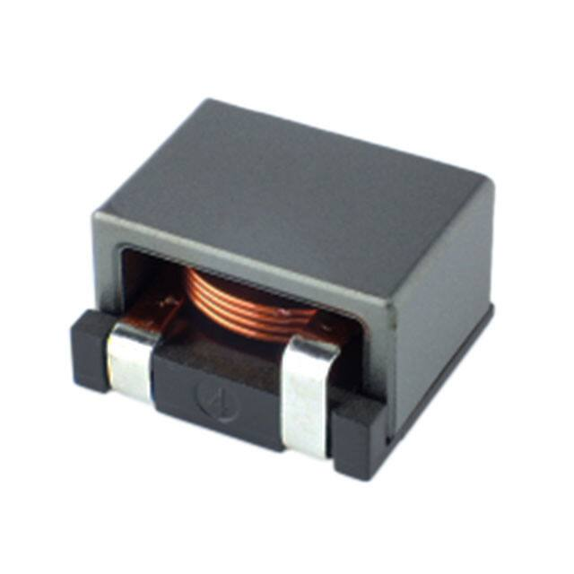


 工商网监
湘ICP备2023018690号
工商网监
湘ICP备2023018690号
