Operator’s
Manual
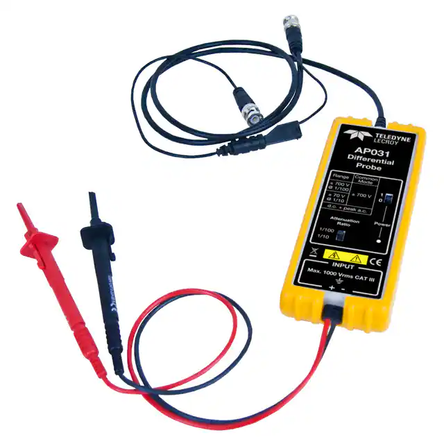
AP031
Differential Probe
��© 2013 Teledyne LeCroy, Inc. All rights reserved.
Unauthorized duplication of Teledyne LeCroy documentation materials other than for internal sales
and distribution purposes is strictly prohibited. However, clients are encouraged to distribute and
duplicate Teledyne LeCroy documentation for their own internal educational purposes.
Teledyne LeCroy is a registered trademarks of Teledyne LeCroy, Inc. Windows is a registered
trademark of Microsoft Corporation. Other product or brand names are trademarks or requested
trademarks of their respective holders. Information in this publication supersedes all earlier versions.
Specifications are subject to change without notice.
923064-00 Rev A
June 2013
Warranty
Teledyne Lecroy warrants this oscilloscope accessory for normal use and operation within specification for a period
of one year from the date of shipment. Spare parts, replacement parts and repairs are warranted for 90 days.
In exercising its warranty, Teledyne Lecroy, at its option, will either repair or replace any assembly returned within
its warranty period to the Customer Service Department or an authorized service center. However, this will be
done only if the product is determined by Teledyne Lecroy’s examination to be defective due to workmanship or
materials, and the defect is not caused by misuse, neglect, accident, abnormal conditions of operation, or damage
resulting from attempted repair or modifications by a non-authorized service facility.
The customer will be responsible for the transportation and insurance charges for the return of products to the
service facility. Teledyne Lecroy will return all products under warranty with transportation charges prepaid.
This warranty replaces all other warranties, expressed or implied, including but not limited to any implied warranty
of merchantability, fitness or adequacy for any particular purposes or use. Teledyne Lecroy shall not be liable for
any special, incidental, or consequential damages, whether in contract or otherwise.
�AP031 Probe
Safety Instructions
This section contains instructions that must be observed to keep this oscilloscope accessory
operating in a correct and safe condition. You are required to follow generally accepted
safety procedures in addition to the precautions specified in this section. The overall safety
of any system incorporating this accessory is the responsibility of the assembler of the
system.
Symbols
These symbols may appear on the probe body or in this manual to alert you to important
safety considerations.
HIGH VOLTAGE, risk of electric shock.
CAUTION of potential for damage to probe or instrument it is connected to or WARNING
of potential bodily injury. Attend to the accompanying information to protect against
personal injury or damage. Do not proceed until conditions are fully understood and met.
ELECTROSTATIC DISCHARGE (ESD) HAZARD. The probe is susceptible to damage if antistatic measures are not taken.
ON (POWER)
OFF (POWER)
DOUBLE INSULATION
MEASUREMENT GROUND TERMINAL
2
923064-00 Rev A
�Operator’s Manual
Precautions
To avoid personal injury or damage to property, review and comply with the following
safety precautions.
Use product only as specified. The probe is designed to make differential voltage
measurements. It is not to be used to insulate the circuit under test from the measuring
instrument.
Do not overload. To avoid electric shock or fire hazard, do not apply any potential that
exceeds the maximum rating of the probe and/or the probe accessory (e.g. probe hooks),
whichever is less.
Connect and disconnect properly. To avoid electric shock or fire hazard, always make the
connections from the probe input leads to the probe hooks before making any connections
to a voltage source. Do not connect or disconnect probe hooks to a votage source unless
they are first connected to the probe input leads. Ensure connections between probe input
leads and probe hooks are secure before connecting them to a voltage source.
Use only accessories compatible with the probe. Use only accessories that are shipped
with the product. Substitution of other accessories may create a potential shock hazard.
Comply with voltage derating curve. When measuring higher frequency signals, comply
with the Voltage vs. Frequency Derating Curve (see Page 7).
Observe all terminal ratings. To avoid electric shock or fire, do not use the probe above the
input limits shown on the probe as well as all accessories.
Do not remove probe casing. Removing the probe’s case or touching exposed connections
may result in electric shock.
Use only within operational environment listed. Do not use in wet or explosive
atmospheres. Keep product surfaces clean and dry.
923064-00 Rev A
3
�AP031 Probe
Avoid damage to cable through excessive bending.
Handle with care. Tips of probe hooks are sharp. They puncture skin or cause other bodily
injury if not handled properly.
Keep fingers behind the finger guard of the probe hooks.
Do not operate with suspected failures. Before each use, inspect the probe and probe
hooks for any potential damage such as tears or other defects in the probe body, cable
jacket, accessories, etc. If any part is damaged, cease operation immediately and sequester
the probe from inadvertent use.
Introduction
The AP031 is a fully differential active probe designed for applications where electrical
signals must be measured relative to a floating voltage different to the oscilloscope ground
potential.
This probe is specifically designed for situations where:
The reference voltage may be several hundreds volts above or below ground.
Measurements require the rejection of common mode signals.
Ground loops and currents produce to excessive signal interference.
The use of the probe ensures safe operation of the oscilloscope and maintains high signal
fidelity with good common mode rejection and dynamic range.
The probe is a fully differential active device. The differential capability allows
measurements to be made between two points in a circuit without reference to ground.
The two input signals are processed inside the probe (see figure 1) and the resulting singleended signal may be measured by any grounded oscilloscope. Because the differential
4
923064-00 Rev A
�Operator’s Manual
voltage is calculated within the probe, with only the resultant difference signal being passed
to the oscilloscope, a large dynamic range can be achieved with excellent rejection of
common mode signals.
Figure 1
923064-00 Rev A
5
�AP031 Probe
Specifications
Electrical Characteristics
Bandwidth
25 MHz
Rise Time
14 ns
Attenuation
1:10 / 1:100
Atten. Accuracy
±2 %
Input Resistance
4 MΩ
Input Capacitance
Input Configuration
Input Voltage
5.5 pF each side to ground
Differential
Max. Differential 1:100 Range
±700 V (DC + AC pk) and 700 V r.m.s.
Max. Differential 1:10 Range
±70 V (DC + AC pk) and 70 V r.m.s.
Max. Common Mode
±700 V ( DC + AC pk) and 700 V r.m.s.
Max. Absolute
±1400 V ( DC + AC pk) and 1000 V r.m.s.
CMRR
6
50 Hz
- 80 dB
20 kHz
- 60 dB
Output Offset (Typical)
很抱歉,暂时无法提供与“AP031”相匹配的价格&库存,您可以联系我们找货
免费人工找货