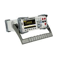
T3DMM5-5 Data Sheet
5.5 Digit Digital Multimeter
Broad Measurement Range
DC: 1000 Volts
AC: 750 Volts
Current: 10A
Tools for Improved Debugging
●●
●●
●●
●●
●●
●●
Wide range of measurements – DC/AC voltage and
Current, Resistance, Capacitance, Frequency, Period,
Temperature, and more.
�More application coverage from a single Digital
multimeter.
True-RMS measurements – All AC Voltage and
Current ranges give True-RMS readings.
�Excellent accuracy regardless of the waveform shape.
Low level measurement, high sensitivity ranges –
Voltage ranges as low as 200 mV full scale, DC Current
200 µA, AC Current 20 mA full scale.
�High sensitivity ranges give greater accuracy of
small signal measurements.
Advanced measurement features – Min, Max,
Average, Standard Deviation dBm/dB, Pass/fail,
Histogram, Trend, Relative measurements.
�Advanced features for today’s measurement needs.
Built-in cold terminal thermocouple compensation –
4.3 inch (10.92 cm) color TFT-LCD 480 x 272 display.
�Accurate Temperature measurements.
USB Device, USB Host and LAN support
�Remote control your measurements.
Key Specifications
DC Voltage
200 mV to 1000 V
DC Current
200 µA to 10 A
True RMS AC Voltage
200 mV to 750 V
True RMS AC Current
20 mA to 10 A
2 /4 Wire Resistance
200 Ohms to 100 MOhms
Connectivity
USB Device, LAN
Remote Control
SCPI, LabView Driver
�PRODUCT OVERVIEW
Teledyne Test Tools T3DMM5-5 is a 5½ digit digital multimeter incorporating the latest 4.3 inch (10.92cm) dualdisplay technology which can be configured to show data histograms, Data fluctuation Trends, Bar Graph, Statistics
or the traditional Number mode, all in an easy to use interface.
A great feature of the Teledyne Test Tools T3DMM5-5 is it’s ability to made highly accurate True RMS AC Voltage and
Current measurements, meaning no loss of accuracy even when measuring complex voltage and current waveforms.
The T3DMM5-5 is especially well suited for the needs of High precision multifunctional environments, as well as
supporting a full range of automatic measurements.
Main Functions
Application fields
Basic Measurement Function
●●
Research Laboratory
●●
DC Voltage: 200 mV ~ 1000 V
●●
Development Laboratory
●●
DC Current: 200 μA ~ 10 A
●●
Repair and Maintenance
●●
AC Voltage: True-RMS, 200 mV ~ 750 V
●●
Calibration Laboratory
●●
AC Current: True-RMS, 20 mA ~ 10 A
●●
Automatic Production Test
●●
2/4-Wire Resistance: 200 Ω ~ 100 MΩ
●●
General bench-top use
●●
Capacitance: 2 nF ~ 10000 μF
●●
Continuity Test: Range is fixed at 2 kΩ
●●
Diode Test: Adjustable range is 0 ~ 4 V.
●●
Real 5½ digit (240,000 count) readings resolution
●●
Frequency Measurement: 20 Hz ~ 1 MHz
●●
Up to 150 rdgs/s measurement speed
●●
Period Measurement: 1 μs ~ 0.05 s
●●
True-RMS AC Voltage and AC Current measuring
●●
Temperature: Support for TC and RTD sensor
●●
Max, Min, Average, Standard Deviation,
dBm/dB, Relative Measurement, Pass/Fail
Histogram, Trend Chart
●●
Built-in cold terminal compensation for thermocouple
●●
Standard interface: USB Device, USB Host, LAN
●●
User-friendly Design
●●
4.3” TFT-LCD, 480*272
●●
Dual display, Chinese and English Menu
●●
Built-in front panel accessible help system
●●
File management (support for U-disc and local storage)
2
Main Features
●●
1 Gb flash memory for mass storage configuration files
and data files
USB & LAN remote interfaces support common SCPI
command set. Compatible with other popular DMMs
on the market.
�SPECIAL FEATURES
Dual Display
Bar Chart
Statistics
Histogram
Trend Chart
Hold Measurement
dBm Hold Measurement
Rear Panel Interfaces
3
�SPECIFICATIONS
DC Characteristic�
Function
DC Voltage
DC Current
Resistance 3)
Diode Test
Continuity Test
Accuracy ± (% of Reading + % of Range) 1)
Range 2)
200 mV
2V
20 V
200 V
1000 V 4)
200 μA
2 mA
20 mA
200 mA
2A
10 A5)
200 Ω
2 KΩ
20 KΩ
200 KΩ
2 MΩ
10 MΩ
100 MΩ
2.0 V6)
4V
2000 Ω
Test current or
Load voltage
1 Year
23 °C ± 5°C
< 8 mV
< 80 mV
< 0.05 V
< 0.5 V
< 0.1 V
< 0.3 V
1 mA
1 mA
100 μA
10 μA
1 μA
200 nA
200 nA || 10 MΩ
1 mA
100 μA
1 mA
0.015 + 0.004
0.015 + 0.003
0.015 + 0.004
0.015 + 0.003
0.015 + 0.003
0.055 + 0.005
0.055 + 0.005
0.095 + 0.020
0.070 + 0.008
0.170 + 0.020
0.250 + 0.010
0.030 + 0.005
0.020 + 0.003
0.020 + 0.003
0.020 + 0.010
0.040 + 0.004
0.250 + 0.003
1.75 + 0.004
0.05 + 0.01
0.05 + 0.01
0.05 + 0.01
Temperature coefficient
0 °C ~ 18 °C
28 °C ~ 50 °C
0.0015 + 0.0005
0.0010 + 0.0005
0.0020 + 0.0005
0.0015 + 0.0005
0.0015 + 0.0005
0.003 + 0.001
0.002 + 0.001
0.008 + 0.001
0.005 + 0.001
0.013 + 0.001
0.008 + 0.001
0.0030 + 0.0006
0.0030 + 0.0005
0.0030 + 0.0005
0.0030 + 0.0005
0.0040 + 0.0005
0.0100 + 0.0005
0.2000 + 0.0005
0.0050 + 0.0005
0.0050 + 0.0005
0.0050 + 0.0005
Remarks:
1)
Specifications are for 0.5 Hour warm-up, “Slow” measurement rate and calibration temperature 18°C ~ 28°C.
2)
20 % over range on all ranges except for DCV 1000 V, ACV 750 V, DCI 10 A and ACI 10 A.
3)
�Specifications are for 4-wire measurement or 2-wire measurement under “REF” operation. ± 0.2 Ω of extra error will be generated if performing a 2-wire measurement
without “REF” operation.
4)
Plus 0.02 mV of error per 1 V after the first ± 500 VDC.
5)
30 seconds OFF / 30 seconds ON is recommend for the continuous current greater than DC 7 A or AC RMS 7 A.
6)
�Accuracy specifications are only for voltage measurements at the input terminals. The typical value of current in the measurement is 1 mA. Voltage drop at the diode
junction may vary with current supply.
4
�SPECIFICATIONS
AC Characteristic�
Function
Accuracy ± (% of Reading + % of Range) 1)
Range 2)
200 mV
2V
True-RMS
AC Voltage 3)
20 V
200 V
750 V
20 mA
200 mA
True-RMS
AC Current 4)
2A
10 A 5)
Frequency Range
1 Year
23 °C ± 5°C
20 Hz – 45 Hz
45 Hz – 20 KHz
20 KHz – 50 KHz
50 KHz –100 KHz
20 Hz – 45 Hz
45 Hz – 20 KHz
20 KHz – 50 KHz
50 KHz –100 KHz
20 Hz – 45 Hz
45 Hz – 20 KHz
20 KHz – 50 KHz
50 KHz –100 KHz
20 Hz – 45 Hz
45 Hz – 20 KHz
20 KHz – 50 KHz
50 KHz –100 KHz
20 Hz – 45 Hz
45 Hz – 20 KHz
20 KHz – 50 KHz
50 KHz –100 KHz
20 Hz – 45 Hz
45 Hz – 2 KHz
2 KHz – 10 KHz
20 Hz – 45 Hz
45 Hz – 2 KHz
2 KHz – 10 KHz
20 Hz – 45 Hz
45 Hz – 2 KHz
2 KHz – 10 KHz
20 Hz – 45 Hz
45 Hz – 2 KHz
2 KHz – 10 KHz
1.5 + 0.10
0.2 + 0.05
1.0 + 0.05
3.0 + 0.05
1.5 + 0.10
0.2 + 0.05
1.0 + 0.05
3.0 + 0.05
1.5 + 0.10
0.2 + 0.05
1.0 + 0.05
3.0 + 0.05
1.5 + 0.10
0.2 + 0.05
1.0 + 0.05
3.0 + 0.05
1.5 + 0.10
0.2 + 0.05
1.0 + 0.05
3.0 + 0.05
1.5 + 0.10
0.50 + 0.10
2.50 + 0.20
1.5 + 0.10
0.50 + 0.10
2.50 + 0.20
1.5 + 0.20
0.50 + 0.20
2.50 + 0.20
1.5 + 0.15
0.50 + 0.15
2.50 + 0.20
Temperature coefficient
0 °C ~ 18 °C
28 °C ~ 50 °C
0.01 + 0.005
0.01 + 0.005
0.01 + 0.005
0.05 + 0.010
0.01 + 0.005
0.01 + 0.005
0.01 + 0.005
0.05 + 0.010
0.01 + 0.005
0.01 + 0.005
0.01 + 0.005
0.05 + 0.010
0.01 + 0.005
0.01 + 0.005
0.01 + 0.005
0.05 + 0.010
0.01 + 0.005
0.01 + 0.005
0.01 + 0.005
0.05 + 0.010
0.015 + 0.015
0.015 + 0.006
0.015 + 0.006
0.015 + 0.005
0.015 + 0.005
0.015 + 0.005
0.015 + 0.005
0.015 + 0.005
0.015 + 0.005
0.015 + 0.005
0.015 + 0.005
0.015 + 0.005
Additional wave crest factor error (not Sine) 6)
Wave crest coefficient
1–2
2–3
Error (% Range)
0.05
0.2
Remarks:
1)
Specifications are for 0.5 Hour warm-up, “Slow” measurement rate and calibration temperature 18°C ~ 28°C.
2)
20 % over range on all ranges except for DCV 1000 V, ACV 750 V, DCI 10 A and ACI 10 A.
3)
�Specifications are for amplitude of sine wave input > 5 % of range. For inputs from 1% to 5 % of range and < 50 kHz, add extra 0.1% of range error.
For 50 kHz to 100 kHz, add extra 0.1% of range error.
4)
Specifications are for sine wave input > 5% of range. 0.1% errors wills be added when the range of input sine wave is 1% to 5 % .
5)
30 seconds OFF / 30 seconds ON is recommend for the continuous current that higher than DC 7 A or AC RMS 7 A.
6)
For frequency < 100 Hz
5
�SPECIFICATIONS
Frequency and Period Characteristic�
Function
Frequency/Period
Accuracy ± (% of Reading + % of Range) 1)
Range
Frequency Range
1 Year
23 °C ± 5°C
200 mV ~ 750 V 2)
20 Hz – 2 KHz
2 KHz – 20 KHz
20 KHz – 200 KHz
200 KHz –1 MHz
0.01 + 0.003
0.01 + 0.003
0.01 + 0.003
0.01 + 0.006
Temperature coefficient
0 °C ~ 18 °C
28 °C ~ 50 °C
0.002 + 0.001
0.002 + 0.001
0.002 + 0.001
0.002 + 0.002
Remarks:
1)
Specifications are for 0.5 Hour warm-up.
2)
�Except for special marks, the AC input voltage is 15 % to 120 % of range when < 100 kHz and 30 % to 120 % of range when >100 kHz. 750 V range is limited to 750 Vrms.
The accuracy is 10 times % of reading when the measurement range of AC voltage is in 200 mV range.
Capacitance Characteristic�
Accuracy ± (% of Reading + % of Range) 1)
Function
Range 2)
Max Testing Current
1 Year
23 °C ± 5°C
Capacitance
2 nF
20 nF
200 nF
2 μF
200 μF
10000 μF
200 nA
200 nA
2 μA
10 μA
100 μA
1 mA
3 + 1.0
1 + 0.5
1 + 0.5
1 + 0.5
1 + 0.5
2 + 0.5
Temperature coefficient
0 °C ~ 18 °C
28 °C ~ 50 °C
0.08 + 0.002
0.02 + 0.001
0.02 + 0.001
0.02 + 0.001
0.02 + 0.001
0.02 + 0.001
Remarks:
1)
Specifications are for 0.5 Hour warm-up and “REF” operation. Using of non-film capacitor may generate additional errors.
2)
Specifications are for from 1% to 120 % on 2 nF range and ranges from 10 % to 120 % on other ranges.
Temperature Characteristic�
Function
Temperature
Accuracy ± (% of Reading + % of Range) 1)
Probe
Type
Probe
Model
Working
Temperature Range
Accuracy (one year;
23 °C ± 5°C)
RTD 2)
α = 0.00385
B
E
J
K
N
R
S
T
-200 °C ~ 660 °C
0 °C ~ 1820 °C
-270 °C ~ 1000 °C
-210 °C ~ 1200 °C
-270 °C ~ 1372 °C
-270 °C ~ 1300 °C
-270 °C ~ 1768 °C
-270 °C ~ 1768 °C
-270 °C ~ 400 °C
0.16 °C
0.76 °C
0.5 °C
0.5 °C
0.5 °C
0.5 °C
0.5 °C
0.6 °C
0.5 °C
TC 3)
Remarks:
1)
Specifications are for 0.5 Hour warm-up, not include probe error.
2)
Specifications are for 4-wire measure or 2-wire measure under “REF” operation.
3)
Built-in cold terminal compensation for thermocouple, accuracy is ± 2°C.
6
Temperature coefficient
0 °C ~ 18°C
28 °C ~ 50 °C
0.08 + 0.002
0.14 °C
0.02 °C
0.02 °C
0.03 °C
0.04 °C
0.09 °C
0.11 °C
0.03 °C
�MEASURING METHOD AND OTHER CHARACTERISTICS
DC Voltage
Input Resistance
Input Bias Current
Input Protection
CMRR
NMRR
200 mV and 2 V Range
10 MΩ or > 10 GΩ selectable
20 V, 200 V and 1000 V Range 10 MΩ ± 2 %
< 90 pA, 25 °C
1000 V on all ranges
120 dB (For the 1 KΩ unbalanced resistance in LO lead, max ± 500 VDC)
60 dB at “slow” measurement rate
20 dB is added if the “AC” filter is open (disconnected).
Resistance
Testing Method
Input Protection
4-wire resistance or 2-wire resistance selectable
1000 V on all ranges
DC Current
Shunt Resistor
Input Protection
200 μA sampling voltage < 8 mV
2 mA sampling voltage < 8 mV
1 Ω for 20 mA and 200 mA
0.01 Ω for 2 A, 10 A
Rear panel : accessible 10 A, 250 V fast-melt fuse
Internal: 12 A, 250 V slow-melt fuse
Continuity/Diode Test
Measurement Method
Beeper
Continuity Threshold
Input Protection
1 mA ± 5 % constant-current source or open-circuit voltage
yes
Adjustable
1000 V
True-RMS AC Voltage
Measurement Method
Wave Crest Factor
Input Impedance
AC Filter Bandwidth
CMRR
AC Coupled true RMS measure – up to 1000 V DC bias are permitted on every range.
≤ 3 at full scale
1 MΩ ± 2 % in parallel with < 100 pF on all ranges
20 Hz ~ 100 KHz
60 dB (For the 1 KΩ imbalance resistance among Lo lead and < 60 Hz, Max ± 500 VDC)
True-RMS AC Current
Measurement Method
Wave Crest Factor
Max Input
Shunt Resistor
Input Protection
DC Coupled to the fuse and shunt; AC Coupled: True-RMS measurement
(measures the AC components only)
≤ 3 at full scale
< 10 A (include DC component)
1 Ω for 20 mA, 200 mA, 0.01 Ω for 2 A, 10 A
Rear panel: accessible 10 A, 250 V fast-melt fuse
Internal: 12 A, 250 V slow-melt fuse
Frequency/Period
Measurement Method
Additional Errors
Reciprocal-counting technique, AC Coupled input, AC voltage or AC current measurement
function
Percentage Error increases in all frequency counters when measuring low voltage or low
frequency signal.
Capacitance Measuring
Measurement Method
Connection Type
Input Protection
Measure the rate of change of voltage generated during the current flow to the capacitor
2-wire
1000 V on all ranges
7
�MEASURING METHOD AND OTHER CHARACTERISTICS
Temperature Measuring
Measurement Method
Support for TC and RTD types of sensor
Trigger and Memory
Samples/Trigger
Trigger Delay
External Trigger Input
VMC
1 ~ 10000
6 ms ~ 10000 ms optional
Input Level �TTL compatible (High level when left input terminal is
hanging in the air)
Trigger Condition
Rising and Falling selectable
Input Impendance
≥ 20 KΩ//400 pF, DC-coupled
Min Pulse
500 us
Level
TTL compatible
Output Polarity
Positive and negative optional
Output Impendance
200 Ω, typical
History Records
Volatile Memory
Nonvolatile Memory
10 K reading history records
1 Gb Nand Flash, Mass storage, configuration files, and data files, Support U-disk external
storage
Math Functions
Min/Max/Average, dBm, dB, Pass/Fail, Relative, Standard deviation, Hold, histogram, Trend chart, Bar chart
General Specifications
Power Supply
AC 100 V ~ 120 V
AC 200 V ~ 240 V
Consumption
Mechanism
Dimension
Weight
Other Characteristics
Display Screen
Operating Environment
Safety
Remote Interface
Programmer Language
Warm Up Time
8
50/60 Hz
50/60 Hz
20 VA max
282 mm × 260 mm × 105 mm
3.33 Kg
4.3” TFT-LCD, resolution 480*272
Full accuracy from 0 to 50 , 80 % RH and 40 °C, non condensing
Storage Temperature: -20 °C – +70 °C
Shock and Vibration: conforming to MIL-T-28800E, 5 level (only for sine)
Height above sea level: up to 3000 meters
Conforming to IEC61010-1:2001. Measure CAT I 1000 V/CAT II 600V
Class of pollution: 2
10/100 Mbit LAN, USB2.0 Full Speed Device and Host
Standard SCPI
30 minutes
�Ordering information
Product Name
Model
Standard Accessories
Teledyne Test Tools T3DMM5-5 Digital Multimeter
T3DMM5-5 5.5 Digit Broad Measurement Range Digital Multimeter
Two Test Leads, Two Alligator Clips
A USB Cable
A Quick Start
A warranty Card
Power Cord
9
�ABOUT TELEDYNE TEST TOOLS
Company Profile
Teledyne LeCroy is a leading provider of oscilloscopes, protocol
analyzers and related test and measurement solutions that
enable companies across a wide range of industries to design
and test electronic devices of all types. Since our founding
in 1964, we have focused on creating products that improve
productivity by helping engineers resolve design issues
faster and more effectively. Oscilloscopes are tools used by
designers and engineers to measure and analyze complex
electronic signals in order to develop high-performance
systems and to validate electronic designs in order to improve
time to market.
The Teledyne Test Tools brand extends the Teledyne LeCroy
product portfolio with a comprehensive range of test
equipment solutions. This new range of products delivers
a broad range of quality test solutions that enable engineers
to rapidly validate product and design and reduce time-tomarket. Designers, engineers and educators rely on Teledyne
Test Tools solutions to meet their most challenging needs for
testing, education and electronics validation.
Location and Facilities
Headquartered in Chestnut Ridge, New York, Teledyne
Test Tools and Teledyne LeCroy has sales, service and
development subsidiaries in the US and throughout
Europe and Asia. Teledyne Test Tools and Teledyne LeCroy
products are employed across a wide variety of industries,
including semiconductor, computer, consumer electronics,
education, military/aerospace, automotive/industrial, and
telecommunications.
Distributed by:
Teledyne LeCroy
(US Headquarters)
700 Chestnut Ridge Road
Chestnut Ridge, NY. USA 10977-6499
Phone:
Fax Sales:
Phone Support:
Email Sales:
Email Support:
Web Site:
800-553-2769 or 845-425-2000
845-578-5985
1-800-553-2769
contact.corp@teledynelecroy.com
support@teledynelecroy.com
http://teledynelecroy.com/
Teledyne LeCroy
(European Headquarters)
Teledyne LeCroy GmbH
Im Breitspiel 11c
D-69126 Heidelberg, Germany
Phone:
Fax:
Phone Service:
Phone Support:
Email Sales:
Email Service:
Email Support:
Web Site:
+49 6221 82700
+49 6221 834655
+49 6221 8270 85
+49 6221 8270 28
contact.gmbh@teledynelecroy.com
service.gmbh@teledynelecroy.com
tlc.t3.appsupport.eu@teledyne.com
http://teledynelecroy.com/germany
teledynelecroy.com
© 2018 Teledyne Test Tools is a brand and trademark of Teledyne LeCroy Inc. All rights reserved. Specifications, prices, availability and delivery subject to change without notice.
Product brand or brand names are trademarks or requested trademarks of their respective holders.
T3 stands for Teledyne Test Tools.
�