T3DSO2000 Data Sheet
Oscilloscopes
Debug with Confidence
100 MHz – 300 MHz
Front panel of the four channel series
Front panel of the two channel series
Tools for Improved Debugging
●●
●●
●●
●●
●●
●●
Long Capture – 70 Mpts/Ch and 140 Mpts interleaved.
�Capture more time and show more waveform detail.
Math and Measure – 7 basic math functions plus FFT
and 37 automatic measurement parameters.
�Extract results from waveforms and measurements.
Connectivity – USB for mass storage, printing and
PC control, plus LAN for fast data transfer.
�Save data for external analysis and screen images
for reports.
Optional Serial Bus Trigger and Decode – I2C, SPI,
UART, RS232, CAN, LIN.
�Debug serial buses directly in your Oscilloscope.
Waveform Sequence Recorder – record and play back
up to 80,000 waveforms.
�Replay the changing waveform history.
Optional MSO – 16 Digital Channels
�Add mixed signal debugging to your Oscilloscope.
Key Specifications
Bandwidth
100 MHz, 200 MHz, 300 MHz
Channels
2 or 4
Memory
70 Mpts/Ch (140 Mpts interleaved)
Sample Rate
up to 2 GS/s (Interleaved)
Display
8" Bright TFT LCD (800 x 480)
Connectivity
USB Host, USB Device, LAN
�PRODUCT OVERVIEW
T3DSO2102: 2 Channel 100 MHz
T3DSO2104: 4 Channel 100 MHz
T3DSO2202: 2 Channel 200 MHz
T3DSO2204: 4 Channel 200 MHz
T3DSO2302: 2 Channel 300 MHz
T3DSO2304: 4 Channel 300 MHz
Teledyne Test Tools new T3DSO2000 Oscilloscopes feature two channel and four channel models with analog
bandwidth options from 100 MHz to 300 MHz. Each model offers a maximum sample rate of 2 GSa/s, and
a maximum memory depth of 140 Mpts in half channel mode. The four channel models incorporates two 2 GSa/s
ADCs and two 140 Mpts memory modules. When all channels are enabled, each channel has sample rate of
1 GSa/s and a standard record length of 70 Mpts. When only a single channel per ADC is active, the maximum
sample rate is 2 GSa/s and the maximum record length is 140 Mpts. For ease-of-use, the most commonly used
functions can be accessed with its user-friendly front panel design.
The�T3DSO2000�series�employs�a new�generation�of�
high speed display technology that provides excellent
signal�clarity,�fi�delity�and�performance.�The�system�noise�
floor is also lower than similar products in the industry. It
comes�with�a minimum�vertical�input�range�of�1�mV/div,�
an innovative digital trigger system with high sensitivity
and�low�jitter,�and�a waveform�capture�rate�of�500,000�
waveforms/sec (sequence mode). The T3DSO2000 also
employs�a 256-level�intensity�grading�display�function�
and�a color�temperature�display�mode�which�complement�
the high speed update rate. Teledyne Test Tools latest
oscilloscope offering supports multiple powerful triggering
modes�including�serial�bus�triggering.�There�is�a low�cost�
option for serial bus decoding of IIC, SPI, UART, CAN, LIN
Key Features
●●
●●
100 MHz, 200 MHz and 300 MHz bandwidth models
●●
●●
Real-time�sampling�rate�up�to�2�Gsa/s
●●
●●
New generation of high speed display technology
Waveform capture rate up to 140,000 wfm/s
� (normal�mode),�and�500,000�wfm/s�(sequence
mode)
�Supports�256-level�intensity�grading�and�color
display modes Record length up to 140 Mpts
Digital trigger system
›
›
›
●●
●●
2
bus types. The models also include History waveform
recording, and sequential triggering that enable extended
waveform recording and analysis. Other options available
include�the�25�MHz�function�/�arbitrary�waveform�
generator�and�the�16�channel�MSO�option.�Both�are�fi�eld�
up gradable options. The new digital design also includes
a hardware�co-processor�that�delivers�measurements�
quickly and accurately without slowing acquisition and
front-panel�response.�The�features�and�performance�of�
Teledyne Test Tools new T3DSO2000 offers outstanding
value for money.
Intelligent trigger: Edge, Slope, Pulse Width, Window,
Runt, Interval,
Time�out�(Dropout),�Pattern�and�Video
●●
●●
Serial bus triggering and decoding (Standard), supports
protocols IIC, SPI, UART, RS232, CAN, LIN
Video�trigger,�supports�HDTV
Low background noise with voltage scales from
1�mV/div�to�10�V/div
10�types�of�one-button�shortcuts,�supports�Auto�Setup,�
Default, Cursors, Measure, Roll, History, Display/Persist,
Clear Sweep, Zoom and Print
Segmented acquisition (Sequence) mode, divides the
maximum record length into multiple segments (up to
80,000), according to trigger conditions set by the user,
with�a very�small�dead�time�segment�to�capture�the�
qualifying event.
�Models and key Specification
Model
T3DSO2102
T3DSO2104
T3DSO2202
T3DSO2204
T3DSO2302
T3DSO2304
Bandwidth
100 MHz
200 MHz
300 MHz
SamplingRate (Max.)
Two�channel�series�have�a single�2�GSa/s�ADC,�four�channel�series�have�two�
2�GSa/s�ADCs.�When�all�channels�are�enabled,�each�channel�has�a maximum�sample�
rate�of�1�GSa/s.�When�a single�channel�per�pair�is�active,�that�channel�has�sample�rate�
of 2 GSa/s
Channels
4 + EXT (four channel series)
2 + EXT (two channel series)
Memory Depth (Max.)
70 Mpts/Ch (not interleave mode);
140 Mpts/Ch (interleave mode)
Waveform Capture Rate (Max.)
140,000�wfm/s�(normal�mode),�500,000�wfm/s�(sequence�mode)
Trigger Type
Edge,�Slope,�Pulse�Width,�Window,�Runt,�Interval,�Dropout,�Pattern,�Video
Serial Trigger and decoder (Optional)
IIC, SPI, UART/RS232, CAN, LIN
16 Digital Channels (MSO option)
Maximum�waveform�capture�rate�up�to�500�MSa/s,�Record�length�up�to�140�Mpts/Ch
Waveform Generator (optional)
One�channel,�25�MHz,�sample�rate�of�125�MHz,�wave�length�of�16�kpts
I/O
USB Host, USB Device, LAN, Pass/Fail, Trigger Out
Probe (Std)
1 for each Channel
Display
8�inch�TFT-LCD�(800�x 480)
●●
●●
●●
●●
●●
●●
History waveform record (History) function,
maximum recorded waveform length is 80,000
frames.
Automatic measurement function for 37 parameters
as well as Measurement Statistics, Zoom, Gating,
Math, History and Reference functions
8 Math functions (FFT, addition, subtraction,
multiplication, division, integration, differential, square
root)
●●
●●
●●
●●
Large�8�inch�TFT-LCD�display�with�800�x�480�resolution
Multiple interface types: USB Host, USB Device
(USB-TMC),�LAN,�Trigger�Out
Supports SCPI remote control commands
Supports�Multi-language�display�and�embedded�online�
help
High Speed hardware based Pass/Fail function
MSO, 16 digital channels. Record Length up to
140 Mpts/Ch
25�MHz�function/arbitrary�waveform�generator,�
built-in�10�waveform�types
3
�FUNCTION & CHARACTERISTICS
2
4
3
1
5
6
8
9
1 �High�Resolution�8-inch�TFT-LCD�
5 �Multi-functional�controls�for�Serial�
2 �Horizontal�controls�of�Timebase,�
6 �Individual�color�coded�channels�
3 �Advanced�Triggering�controls�
7 �Optional�25�MHz�built�in�arbitrary�
display for clear images.
Zoom, Roll and trigger position.
including Edge, Pulse, Interval,
Window, Slope, DropOut, Runt and
Pattern trigger types.
4 �Easy�to�use�Auto�Setup,�
Run / Stop and Default Controls.
8 inch TFT-LCD display and
10 one-button menus
8-inch�TFT-LCD�display�with�800�x 480�resolution
●● Most commonly used functions are accessible using
10�different�one-button�operation�keys:�Auto�Setup,�
Default, Cursor, Measure, Roll, History, Persist, Clear
●● Sweep, Zoom, Print
●●
4
Decode, Math and Digital inputs.
and display for ease of use.
waveform generator.
8 �Probe�compensation�calibrator.
9 �Color�coded�input�channels.
7
�A Wide Range Of Trigger Functions
Record Length of up to 140 Mpts
A wide rage of powerful triggering functions including
Edge,�Slope,�Pulse,�Video,�Window,�Runt,�Interval,�
Dropout, Pattern, etc, allows users to debug complex
hardware issues with ease.
The record length of up to 140 Mpts allows use of
a higher�sampling�rate�to�capture�more�signal�detail.�
The�hardware-based�Zoom�then�allows�quick�zoom�
in to any area of interest.
256-level Intensity Grading and
Color Temperature Display
256-level�intensity�graded�waveform�display�is�ideal�
for viewing modulated and changing waveforms.
Waveform Capture Rate
up to 500,000 wfm/s
With�a waveform�capture�rate�of�up�to�500,000�wfm/s�
(sequence mode) and 140,000 wfm/s (standard mode)
the T3DSO2000 can easily capture glitches, infrequent
anomalies�and�other�low-probability�events.
History Mode
The Color temperature display clearly shows noise and
jitter with infrequently occurring waveforms shown in
blue through to the most frequently occurring waveforms
shown in red.
The always enabled History mode records up to
80,000 waveforms allowing users to scroll back through
previous acquisitions to observe past events and
locate anomalies quickly.
5
�FUNCTION & CHARACTERISTICS
Sequence Mode
Advanced Math Function
Segmented memory mode can store up to 80,000
waveforms into memory segments for capturing fast
pulses in quick succession. Combine Sequence Mode
with advanced triggers to isolate rare events. All the
segments can be play back using the History function.
The standard Math operations include Plus, Minus,
Multiply, Divide, FFT, integration, differential, and square
root for quick insight into waveform characteristics.
Comprehensive Statistical Functions
Eres Mode
Parametric statistical data for 5 parameters can be
displayed simultaneously. The statistical measurements
include: Current Value, Mean Value, Minimum Value,
Maximum Value, Standard Deviation, and the
measurement count.
Enhanced Resolution (Eres) mode reveals hidden
waveform detail by using a linear average filter to reduce
waveform noise, even on single acquisition waveforms.
6
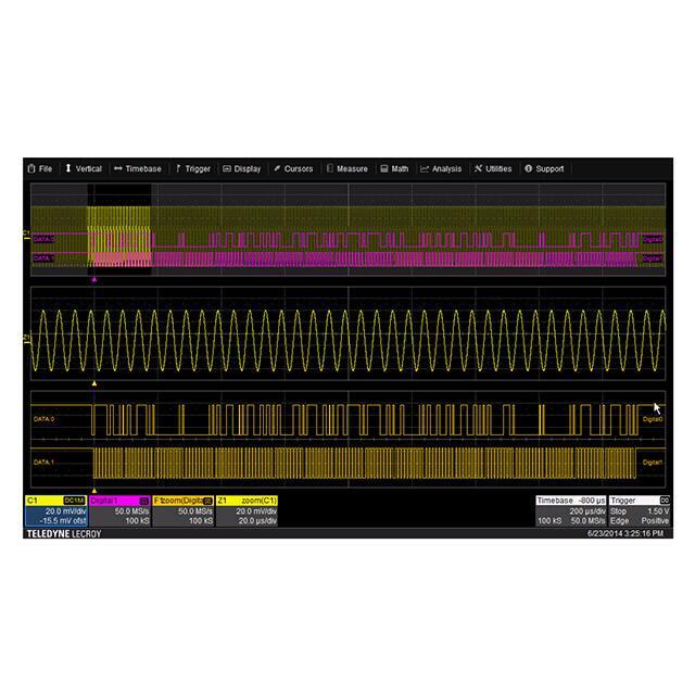
�16 Digital Channels / MSO (Optional)
Complete Connectivity
The MSO option adds 16 digital channels to the
T3DSO2000 analog channels enabling users to trigger
and acquire digital as well as analog waveforms in
a mixed signal debug environment.
Connectivity includes External Trigger Input, Pass/Fail
and Trigger Out, USB Device (USBTMC) and LAN(VXI-11)
for remote control, and a Kensington Lock security point.
Serial Bus Decoding Function (Optional)
Built-in 25 MHz Function/Arbitrary Waveform
Generator (Optional)
Trigger and decode up to 2 common embedded and
automotive serial buses (I2C, SPI, UART/RS232, LIN and
CAN) simultaneously with the T3DSO2000-TD option.
Bus protocol information can be quickly and intuitively
displayed time aligned with the waveform and in table
format.
The optional built-in 25 MHz function generator
(T3DSO2000-FG) comprises 10 built-in waveforms.
4 of your own arbitrary waveforms can be created
and downloaded via PC waveform editing software.
7
�SPECIFICATIONS
All specifications are not guaranteed unless the following conditions are met:
●● The oscilloscope calibration period is valid
●● The oscilloscope has been working continuously for at least 30 minutes at the specified temperature (18 ~ 28 )
Acquire System
Sampling Rate
Memory Depth
Peak Detect
Average
Eres
Interpolation
2 GSa/s (single-channel 1) ), 1 GSa/s (dual-channel)
140 Mpts (single-channel), 70 Mpts (dual-channel)
1 ns
Averages: 4, 16, 32, 64, 128, 256, 512, 1024
Enhance bits: 0.5, 1, 1.5, 2., 2.5, 3 selectable
Sinx/x, Linear
Input
Channels
Coupling
Impedance
Max.Input voltage
CH to CH Isolation
Probe Attenuation
2/4 + EXT
DC, AC, GND
DC: (1 MΩ ± 2 %) || (22 pF ± 3 pF)
50 Ω: 50 Ω ± 2 %
1 MΩ ≤ 400 Vpk (DC + Peak AC 35 dB
0.1X, 0.2X, 0.5X, 1X, 2X, 5X, 10X, 20X, 50X, 100X, 200X, 500X, 1000X, 2000X, 5000X, 10000X
Horizontal System
Time Scale
Channel Skew
Waveform Capture Rate
Intensity grading
Display Format
Time base Accuracy
Roll Mode
1.0 ns/div ~ 50 s/div
< 100 ps
Up to 140,000 wfm/s (normal mode), 500,000 wfm/s (sequence mode)
256-level
Y-T, X-Y, Roll
± 25 ppm
50 ms/div ~ 50 s/div (1-2-5 Step)
Vertical System
Bandwidth (-3dB)
Vertical Resolution
Vertical Range
Vertical Scale (Probe 1X)
Offset Range (Probe 1X)
Bandwidth Limit
Bandwidth Flatness
Low Frequency Response
(AC Coupling –3 dB)
Noise
DC Gain Accuracy
Offset Accuracy
Rise Time 1)
Overshoot (500 ps Rise Edge)
8
300 MHz (SDS2304X / SDS2302X)
200 MHz (SDS2204X / SDS2202X)
100 MHz (SDS2104X / SDS2102X)
70 MHz (SDS2074X / SDS2072X)
8 bit
8 divisions
1 mV/div – 10 V/div (1-2-5 step)
1 mV/div ~ 100 mV/div: ±1 V
102 mV/div ~ 1 V/div: ±10 V
1.02 V/div ~ 10 V/div: ±100 V
20 MHz ± 40 %
DC ~ 10 % (BW): ± 1 dB
10 % ~ 50 % (BW): ± 2 dB
50 % ~ 100 % (BW): + 2 dB/–3 dB
≤ 10 Hz (at input BNC)
stdev ≤ 0.2 div (< 2 mV/div)
stdev ≤ 0.5 div (≥ 2 mV/div)
5 mV/div ~ 10 V/div: ≤ 3.0 %
≤ 2 mV/div: ≤ 4.0 %
≥ 2 mV/div: ± (1 % * offset + 1.5 % * 8 * div + 2 mV)
< 2 mV/div: ± (1 % * offset + 1.5 % * 8 * div + 1 mV)
(Typ.) < 1.2 ns (SDS2304X / SDS2302X)
(Typ.) < 1.7 ns (SDS2204X / SDS2202X)
(Typ.) < 3.5 ns (SDS2104X / SDS2102X)
(Typ.) < 5.0 ns (SDS2074X / SDS2072X)
< 10 %
�Trigger System
Mode
Level
Holdoff Range
Coupling
Coupling Frequency Response
(CH1 ~ CH4) 2)
Coupling Frequency Response
(EXT) 2)
Accuracy 2)
Sensitivity
Jitter
Displacement
Auto, Normal, Single
Internal: ± 4.5 div from the center of the screen
EXT: ± 0.6 V
EXT/5: ± 3 V
100 ns ~ 1.5 s
AC, DC, LFRJ, HFRJ, Noise RJ (CH1 ~ CH4)
DC: Passes all components of the signal
AC: Blocks DC components and attenuates signals below 8 Hz
LFRJ: Attenuates the frequency components below 900 kHz
HFRJ: Attenuates the frequency components above 500 kHz
DC: Passes all components of the signal
AC: Blocks DC components and attenuates signals below 8 Hz
LFRJ: Attenuates the frequency components below 400 kHz
HFRJ: Attenuates the frequency components above 1 MHz
CH1 ~ CH4: ± 0.2 div
EXT: ± 0.3 div
CH1 ~ CH4: 0.6 div
EXT: 200 mVpp (DC ~ 10 MHz)
300 mVpp (10 MHz ~ BW)
EXT/5: 1 Vpp (DC ~ 10 MHz)
1.5 Vpp (10 MHz ~ BW)
< 100 ps (CH1 ~ CH4)
Pre-Trigger: 0 ~ 100 % memory
Delay-Trigger: 0 ~ 2,000 div
Edge Trigger
Slope
Source
Rising, Falling, Rising & Falling
CH1 ~ CH4/EXT/(EXT/5)/AC Line
Slope Trigger
Slope
Limit Range
Source
Time Range
Resolution
Rising, Falling
, < >, > <
CH1 ~ CH4
2 ns ~ 4.2 s
1 ns
Pulse Width Trigger
Polarity
Limit Range
Source
Pulse Width Range
Resolution
+wid , -wid
, < >, > <
CH1 ~ CH4
2 ns ~ 4.2 s
1 ns
Video Trigger
Signal Standard
Source
Sync
Trigger condition
NTSC, PAL, 720p/50, 720p/60, 1080p/50, 1080p/60, 1080i/50, 1080i/60, Custom
CH1 ~ CH4
Any, Select
Line, Field
Window Trigger
Window Type
Source
Absolute, Relative
CH1 ~ CH4
1)
�Single-channel: one channel in CH1/CH2 (or CH3/CH4) is ON and another is OFF
Dual-channel: both channels in CH1/CH2 (or CH3/CH4) are ON
2)
Typical Value refers to the tested value under specific conditions. It might vary with the ambient temperature or other conditions
9
�SPECIFICATIONS
Interval Trigger
Slope
Limit Range
Source
Time Range
Resolution
Rising, Falling
,,><
CH1 ~ CH4
2 ns ~ 4.2 s
1 ns
Dropout Trigger
Timeout Type
Source
Slope
Time Range
Resolution
Edge, State
CH1 ~ CH4
Rising, Falling
2 ns ~ 4.2 s
1 ns
Runt Trigger
Polarity
Limit Range
Source
Time Range
Resolution
+wid , -wid
,,><
CH1 ~ CH4
2 ns ~ 4.2 s
1 ns
Pattern Trigger
Pattern Setting
Logic
Source
Limit Range
Time Range
Resolution
Invalid, Low, High
AND, OR, NAND, NOR
CH1 ~ CH4
,,><
2 ns ~ 4.2 s
1 ns
Serial Trigger
IIC Trigger
Condition
Source (SDA/SCL)
Data format
Limit Range
Data Length
R/W bit
SPI Trigger
Condition
Source (CS/CL/Data)
Data format
Data Length
Bit Value
Bit Order
10
Start, Stop, Restart, No Ack, EEPROM, Address&Data, Data Length
CH1 ~ CH4
Hex
EEPROM: =, >, <
EEPROM: 1 byte
Address & Data: 1 ~ 2 byte
Data Length: 1 ~ 12 byte
Address & Data: Read, Write, Do not care
Data
CH1 ~ CH4
Binary
4 ~ 96 bit
0, 1, X
LSB, MSB
�UART / RS232 Trigger
Condition
Source (RX/TX)
Data format
Limit Range
Data Length
Data Width
Parity Check
Stop Bit
Idle Level
Baud Rate (Selectable)
Baud Rate (Custom)
CAN Trigger
Type
Source
ID
Data format
Data Length
Baud Rate (Selectable)
Baud Rate (Custom)
LIN Trigger
Type
Source
ID
Data format
Data Length
Baud Rate (Selectable)
Baud Rate (Custom)
Start, Stop, Data, Parity Error
CH1 ~ CH4
Hex
=, >, <
1 byte
5 bit, 6 bit, 7 bit, 8 bit
None, Odd, Even
1 bit, 1.5 bit, 2 bit
High, Low
600/1200/2400/4800/9600/19200/38400/57600/115200 bit/s
300 bit/s ~ 334000 bit/s
All, Remote, ID, ID + Data, Error
CH1 ~ CH4
STD (11 bit), EXT (29 bit)
Hex
1~2 byte
5 k/10 k/20 k/50 k/100 k/125 k/250 k/500 k/800 k/1 M bit/s
5 kbit/s ~ 1 Mbit/s
Break, Frame ID, ID+Data, Error
CH1 ~ CH4
1 byte
Hex
1 ~ 2 byte
600/1200/2400/4800/9600/19200 bit/s
300 bit/s ~ 20 kbit/s
Serial Decoder (Optional)
No. of Decoder
IIC Decoder
Signal
Address
Threshold
List
SPI Decoder
Signal
Edge Select
Idle Level
Bit Order
Threshold
List
UART / RS232 Decoder
Signal
Data Width
Parity Check
Stop Bit
Idle Level
Threshold
List
CAN Decoder
Signal
Source
Threshold
List
LIN Decoder
LIN Specification Package Revision
Threshold
List
2
SCL, SDA
7 bit, 10 bit
-4.5 ~ 4.5 div
1 ~ 7 lines
CLK, MISO, MOSI, CS
Rising, Falling
Low, High
MSB, LSB
-4.5 ~ 4.5 div
1 ~ 7 lines
RX, TX
5 bit, 6 bit, 7 bit, 8 bit
None, Odd, Even
1 bit, 1.5 bit, 2 bit
Low, High
-4.5 ~ 4.5 div
1 ~ 7 lines
CAN_H, CAN_L
CAN_H, CAN_L, CAN_H-CAN_L
-4.5 ~ 4.5 div
1 ~ 7 lines
Ver1.3, Ver2.0
-4.5 ~ 4.5 div
1 ~ 7 lines
11
�SPECIFICATIONS
Measurement
Source
No. of Measurements
Range
Measurement Parameters (37 Types)
Vertical (Voltage)
Horizontal (Time)
Delay
Cursors
Statistics
Counter
12
CH1 ~ CH4, Math, Ref, History
Display 5 measurements at the same time
Screen, Gating
Vmax
Vmin
Vpp
Vamp
� ighest value in input waveform
H
�Lowest value in input waveform
�Difference between maximum and minimum data values
�Difference between top and base in a bimodal signal, or between max
and min in an unimodal signal
Vtop
Value of most probable higher state in a bimodal waveform
Vbase
Value of most probable lower state in a bimodal waveform
Mean
Average of all data values
Vmean
Average of data values in the first cycle
stdev
Standard deviation of all data values
Vstd
Standard deviation of all data values in the first cycle
Vrms
Root mean square of all data values
Crms
Root mean square of all data values in the first cycle
FOV
Overshoot after a falling edge; (base-min)/Amplitude
FPRE
Overshoot before a falling edge; (max-top)/Amplitude
ROV
Overshoot after a rising edge; (max-top)/Amplitude
RPRE
Overshoot before a rising edge; (base-min)/Amplitude
Level@X
The voltage value of the trigger point
Period
Period for every cycle in waveform at the 50 % level, and positive slope
Freq
Frequency for every cycle in waveform at the 50 % level, and positive slope
+Wid
Width measured at 50 % level and positive slope
-Wid
Width measured at 50 % level and negative slope
Rise
Time Duration of rising edge from 10 – 90 %
Fall
Time Duration of falling edge from 90 – 10 %
Bwid
�Time from the first rising edge to the last falling edge, or the first falling edge
to the last rising edge at the 50 % crossing
+Dut
Ratio of positive width to period
-Dut
Ratio of negative width to period
Delay
Time from the trigger to the first transition at the 50 % crossing
Time@Level Time from trigger of each transition at a specific level and slope
Phase
Calculate the phase difference between two edges
FRR
Time between the first rising edges of the two channels
FRF
Time from the first rising edge of channel A, to the first falling edge of channel B
FFR
Time from the first falling edge of channel A, to the first rising edge of channel B
FFF
Time from the first falling edge of channel A, to the first falling edge of channel B
LRR
Time from the first rising edge of channel A, to the last rising edge of channel B
LRF
Time from the first rising edge of channel A, to the last falling edge of channel B
LFR
Time from the first falling edge of channel A, to the last rising edge of channel B
LFF
Time from the first falling edge of channel A, to the last falling edge of channel B
Manual: Time X1, X2, (X1-X2), (1/ΔT)
Voltage Y1, Y2, (Y1-Y2)
Track: Time X1, X2, (X1-X2)
Current, Mean, Min,
± 1 Hz counter error
�Math
Operation
FFT window
FFT display
+, -, *, /, FFT, d/dt, ∫dt, square root
Rectangular, Blackman, Hanning, Hamming
Full Screen, Split
Built-in Function/Arbitrary Waveform Generator (Optional)
Channel
Max. Output Frequency
Sampling Rate
Frequency Resolution
Frequency Accuracy
Vertical Resolution
Amplitude Range
Waveforms
Output Impedance
Protection
1
25 MHz
125 MSa/s
1 μHz
± 50 ppm
14 bits
2 mVpp ~ 3 Vpp (into 50 Ω)
4 mVpp ~ 6 Vpp (into HiZ)
Sine, Square, Ramp, Pulse, DC, Noise, Cardiac, Gaus Pulse, Exp Rise, Exp Fall, Arb
50 Ω ± 2 %
Short-Circuit Protection
Sine
Frequency
Offset Accuracy (100 kHz)
Amplitude Flatness
(Compare to 100 kHz, 5 Vpp)
SFDR
HD
1 μHz ~ 25 MHz
± (0.3 dB * offset setting value + 1 mVpp)
± 0.3 dB
DC ~ 1 MHz -60 dBc
1 MHz ~ 5 MHz -55 dBc
5 MHz ~ 25 MHz -50 dBc
DC ~ 5 MHz -50 dBc
5 MHz ~ 25 MHz -45 dBc
Square/Pulse
Frequency
Duty Cycle
Rise/Fall time
Overshoot
Pulse Width
Jitter
1 μHz ~ 10 MHz
20 % ~ 80 %
< 24 ns (10 % ~ 90 %)
< 3 % (typical, 1 KHz, 1 Vpp)
> 50 ns
< 500 ps + 10 ppm
Ramp
Frequency
Linearity (Typical)
Symmetry
1 μHz ~ 300 kHz
< 0.1 % of Pk-Pk (Typical, 1 kHz, 1 Vpp, 100 % Symmetry)
0 % ~ 100 %
DC
Offset range
Accuracy
± 1.5 V (into 50 Ω)
± 3 V (into HiZ)
± (|offset| * 1 % + 3 mV)
Noise
Bandwidth
> 25 MHz (-3 dB)
Arb
Frequency
Wave Length
Sampling Rate
Waveform Import
1 μHz ~ 5 MHz
16 Kpts
125 MSa/s
EasyWave, U-Disk
13
�SPECIFICATIONS
Digital Channels
No. of Channels
Max. Sampling Rate
Memory Depth
Min. Detectable Pulse Width
Level Group
Level Range
Logic Type
Skew 2)
16
500 MSa/s
14 Mpts/Ch
4 ns
D0 ~ D7, D8 ~ D15
-3 V ~ 3 V
TTL, CMOS, LVCMOS3.3, LVCMOS2.5, custom
D0 ~ D15: ± 1 sampling interval
Digital to Analog: ± (1 sampling interval +1 ns)
I/O
Standard
Pass/Fail
USB Host, USB Device, LAN, Pass/Fail, Trigger Out
3.3 V TTL Output
Display
Display Type
Resolution
Color
Contrast
Backlight
Range
8-inch TFT LCD
800 × 480
24 bit
500:1
300 nit
8 x 14 divisions
Waveform Display
Type
Persistence Time
Color Display
Screen Saver
Dot, Vector
OFF, 1 s, 5 s, 10 s, 30 s, infinite
Normal, Color
1 min, 5 min, 10 min, 30 min, 1 hour, OFF
Language
Language
Simplified Chinese, Traditional Chinese, English, French, Japanese, Korean,
German, Russian, Italian, Portuguese
Environments
Temperature
Humidity
Altitude
Electromagnetic Compatibility
Safety
Operating: 10 ~ 40
Non-operating: -20 ~ 60
Operating: 85 % RH, 40 Deg C, 24 hours
Non-operating: 85 % RH, 65 Deg C, 24 hours
Operating: ≤ 3000 m
Non-operating: ≤ 15,266 m
2004/108/EC
Execution Standard EN 61326-1:2006
EN 61000-3-2:2006 + A2:2009, EN 61000-3-3:2008
2006/95/EC
Execution Standard EN 61010-1:2010 / EN 61010-2-030:2010
Power Supply
Input Voltage & Frequency
Power
100 ~ 240 Vrms 50/60 Hz
100 ~ 120 Vrms 400 Hz
25 W Max
Mechanical
Dimensions
Weight
2)
Length * Width * Height = 352 mm * 128 mm * 224 mm
N.W 3.4 Kg (2-ch); 3.6 Kg (4-ch)
G.W 4.9 Kg (2-ch); 5.2 Kg (4-ch)
Typical Value refers to the tested value under specific conditions. It might vary with the ambient temperature or other conditions
14
�T3DSO2000 Probes
Probe type
Model
Passive
T3PP300
300 MHz bandwidth, 1 Mohm 10X Probe 1 supplied per channel.
Logic Probe
T3DSO2000-LS
16 Channel Logic Probe. This probe REQUIRES that the Oscilloscope
has option T3DSO2000-MSO
MSO Software
T3DSO2000MSO1)
Software License for the MSO capability. Enables one T3DSO2000-LS
16 channel logic probe lead set to be shared amongst several licensed
T3DSO2000 oscilloscopes. This software option does not come with
a logic probe lead set.
Current
T3CP50
Bandwidth: 50 MHz, Max. continuous current: 30 Arms,
Peak current: 50A
Switch Ratio: 100 mV/A, 1 V/A, Accuracy: 1 V/A (±1 % ±1 mA),
100 mV/A (±1 % ±10 mA), DC 12 V / 1.2 A power adapter
High Voltage
Differential
T3DP7000
Bandwidth: 100 MHz
Differential Range: 7000 V (DC + Peak AC),
100X/1000X
Accuracy: ±2 %
DC 5 V/1 A USB adapter
High Voltage
T3VP100
Bandwidth: 40 MHz
Differential Range: DC 10 KV, AC (rms): 7 KV (sine),
AC (Vpp): 20KV (Pulse)
1000X
Accuracy: ≤ 3 %
1)
Picture
Description
This probe REQUIRES that the scope has option T3DSO2000-MSO.
Ordering information
Description
Standard Accessories
Optional Accessories
300 MHz, 4 Ch, 2 GSa/s (Max.), 140 Mpts
300 MHz, 2 Ch, 2 GSa/s (Max.), 140 Mpts
200 MHz, 4 Ch, 2 GSa/s (Max.), 140 Mpts
200 MHz, 2 Ch, 2 GSa/s (Max.), 140 Mpts
100 MHz, 4 Ch, 2 GSa/s (Max.), 140 Mpts
100 MHz, 2 Ch, 2 GSa/s (Max.), 140 Mpts
USB Cable -1
Passive Probe -2 (2-ch model); -4 (4-ch model)
Power Cord -1
Quick Start -1
Certificate of Calibration -1
T3DSO2000-TD
T3DSO2000-FG
T3DSO2000-MSO
T3DSO2000-LS
T3VP100
T3CP50
T3DP7000
T3DSO2304
T3DSO2302
T3DSO2204
T3DSO2202
T3DSO2104
T3DSO2102
IIC, SPI, UART/RS232, CAN, LIN Decoder
25 MHz Function/Arbitrary Waveform Generator
16 Digital Channels(Software, requires T3DSO2000-LS
16 Channel Logic Probe, requires T3DSO2000-MSO
High Voltage Probe
Current Probe
High Voltage Differential Probe
15
�ABOUT TELEDYNE TEST TOOLS
Company Profile
Teledyne LeCroy is a leading provider of oscilloscopes, protocol
analyzers and related test and measurement solutions that
enable companies across a wide range of industries to design
and test electronic devices of all types. Since our founding
in 1964, we have focused on creating products that improve
productivity by helping engineers resolve design issues
faster and more effectively. Oscilloscopes are tools used by
designers and engineers to measure and analyze complex
electronic signals in order to develop high-performance
systems and to validate electronic designs in order to improve
time to market.
The Teledyne Test Tools brand extends the Teledyne LeCroy
product portfolio with a comprehensive range of test
equipment solutions. This new range of products delivers
a broad range of quality test solutions that enable engineers
to rapidly validate product and design and reduce time-tomarket. Designers, engineers and educators rely on Teledyne
Test Tools solutions to meet their most challenging needs for
testing, education and electronics validation.
Location and Facilities
Headquartered in Chestnut Ridge, New York, Teledyne
Test Tools and Teledyne LeCroy has sales, service and
development subsidiaries in the US and throughout
Europe and Asia. Teledyne Test Tools and Teledyne LeCroy
products are employed across a wide variety of industries,
including semiconductor, computer, consumer electronics,
education, military/aerospace, automotive/industrial, and
telecommunications.
Distributed by:
Teledyne LeCroy
(US Headquarters)
700 Chestnut Ridge Road
Chestnut Ridge, NY. USA 10977-6499
Phone:
Fax Sales:
Phone Support:
Email Sales:
Email Support:
Web Site:
800-553-2769 or 845-425-2000
845-578-5985
1-800-553-2769
contact.corp@teledynelecroy.com
support@teledynelecroy.com
http://teledynelecroy.com/
Teledyne LeCroy
(European Headquarters)
Teledyne LeCroy GmbH
Im Breitspiel 11c
D-69126 Heidelberg, Germany
Phone:
Fax:
Phone Service:
Phone Support:
Email Sales:
Email Service:
Email Support:
Web Site:
+49 6221 82700
+49 6221 834655
+49 6221 8270 85
+49 6221 8270 28
contact.gmbh@teledynelecroy.com
service.gmbh@teledynelecroy.com
tlc.t3.appsupport.eu@teledyne.com
http://teledynelecroy.com/germany
teledynelecroy.com
© 2018 Teledyne Test Tools is a brand and trademark of Teledyne LeCroy Inc. All rights reserved. Specifications, prices, availability and delivery subject to change without notice.
Product brand or brand names are trademarks or requested trademarks of their respective holders.
T3 stands for Teledyne Test Tools.
�