Bulletin I2195 Rev A. 05/06
SAFEIR Series
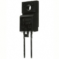
10ETS..FPPbF
INPUT RECTIFIER DIODE
TO-220 FULLPAK
VF < 1.1V @ 10A
Lead-Free ("PbF" suffix)
IFSM = 200A
VRRM = 800 -1200V
Description/ Features
The 10ETS12FPPbF rectifier SAFEIR series
has been optimized for very low forward
voltage drop, with moderate leakage. The
glass passivation technology used has reliable
operation up to 150°C junction temperature.
Typical applications are in input rectification
and these products are designed to be used
with International Rectifier Switches and
Output Rectifiers which are available in
identical package outlines. Fully isolated
package (VINS = 2500 VRMS).
UL E78996 approved
Output Current in Typical Applications
Applications
Single-phase Bridge
Three-phase Bridge
Units
12.0
16.0
A
Capacitive input filter TA = 55°C, TJ = 125°C
common heatsink of 1°C/ W
Major Ratings and Characteristics
Characteristics
IF(AV) Sinusoidal waveform
VRRM Range
IFSM
VF
@ 10 A, TJ = 25°C
TJ
Document Number: 94335
Package Outline
Values
Units
10
A
800 -1200
V
200
A
1.1
V
- 40 to 150
°C
TO-220AC FULLPAK
www.vishay.com
1
�10ETS..FPPbF SAFEIR Series
Bulletin I2195 Rev. A 05/06
Voltage Ratings
Part Number
VRRM , maximum
peak reverse voltage
V
VRSM , maximum non repetitive
peak reverse voltage
V
IRRM
150°C
mA
10ETS12FPPbF
1200
1300
0.5
10ETS08FPPbF
800
900
0.5
Absolute Maximum Ratings
Parameters
Values
Units
10
A
IF(AV) Max. Average Forward Current
IFSM
I2t
Max. Peak One Cycle Non-Repetitive
170
Surge Current
200
Max. I2t for fusing
130
A
Max. I2√t for fusing
@ TC = 105° C, 180° conduction half sine wave
10ms Sine pulse, rated VRRM applied
10ms Sine pulse, no voltage reapplied
A2s
145
I2√t
Conditions
10ms Sine pulse, rated VRRM applied
10ms Sine pulse, no voltage reapplied
1450
A2√s
Values
Units
t = 0.1 to 10ms, no voltage reapplied
Electrical Specifications
Parameters
VFM
Max. Forward Voltage Drop
1.1
V
rt
Forward slope resistance
20
mΩ
VF(TO) Threshold voltage
0.82
V
IRM
0.05
Max. Reverse Leakage Current
mA
0.50
Conditions
@ 10A, TJ = 25°C
TJ = 150°C
TJ = 25 °C
TJ = 150 °C
VR = rated VRRM
Thermal-Mechanical Specifications
Parameters
Values
Units
TJ
Max. Junction Temperature Range
- 40 to 150
°C
Tstg
Max. Storage Temperature Range
- 40 to 150
°C
RthJC Max. Thermal Resistance Junction
to Case
RthJA Max. Thermal Resistance Junction
to Ambient
2.5
°C/W
62
°C/W
RthCS Typical Thermal Resistance, Case to
Heatsink
0.5
°C/W
2 (0.07)
g (oz.)
Min.
6 (5)
Max.
12 (10)
Kg-cm
(Ibf-in)
wt
Approximate Weight
T
Mounting Torque
Case Style
Document Number: 94335
TO-220 FULLPAK
Conditions
DC operation
Mounting surface , smooth and greased
(94/V0)
www.vishay.com
2
�10ETS..FPPbF SAFEIR Series
150
10ETS.. Series
R thJC (DC) = 2.5 °C/ W
140
130
Conduction Angle
120
110
100
30°
60°
90
90°
120°
180°
80
0
2
4
6
8
10
12
Maximum Allowable Case Temperat ure (°C)
Maximum Allowable Case Temperature (°C)
Bulletin I2195 Rev. A 05/06
150
10ETS.. Series
R thJC (DC) = 2.5 °C/ W
140
130
Conduction Period
120
110
30°
60°
100
90°
120°
0
2
Average Forwa rd Current (A)
10
RMSLimit
8
6
Conduction Angle
10ETS.. Series
TJ = 150°C
2
0
0
2
4
6
8
10
Maximum Average Forward Power Loss (W)
180°
120°
90°
60°
30°
4
4
6
8
10
12
14
16
18
Fig. 2 - Current Rating Characteristics
20
DC
180°
120°
90°
60°
30°
18
16
14
12
10
RMS Limit
8
6
Conduction Period
4
10ETS.. Series
TJ = 150°C
2
0
0
2
4
6
8
10
12
14
16
Average Forward Current (A)
Average Forward Current (A)
Fig. 3 - Forward Power Loss Characteristics
Fig. 4 - Forward Power Loss Characteristics
200
At Any Ra ted Load Condition And With
Rated V RRM Ap plied Following Surge.
Initial TJ = 150°C
@60 Hz 0.0083 s
@50 Hz 0.0100 s
180
160
140
120
100
80
10ETS.. Series
60
40
1
10
100
Number Of Equal Amplitude Half Cycle Current Pulses (N)
Fig. 5 - Maximum Non-Repetitive Surge Current
Document Number: 94335
Peak Half Sine Wave Forward Current (A)
Maximum Average Forward Power Loss (W)
Peak Half Sine Wave Forward Current (A)
16
12
DC
Average Forward Current (A)
Fig. 1 - Current Rating Characteristics
14
180°
90
240
Ma ximum Non Rep etitive Surge Current
Versus Pulse Train Dura tion.
Initial TJ = 150 °C
200
No Voltage Reapplied
Rated VRRM Reapplied
180
220
160
140
120
100
80
60
40
0.01
10ETS.. Series
0.1
1
Pulse Train Duration (s)
Fig. 6 - Maximum Non-Repetitive Surge Current
www.vishay.com
3
�10ETS..FPPbF SAFEIR Series
Bulletin I2195 Rev. A 05/06
Instantaneous Forward Current (A)
100
TJ= 25°C
TJ= 150°C
10
10ETS.. Series
1
0
0.5
1
1.5
2
2.5
3
Instantaneous Forward Voltage (V)
Transient Thermal Impedance Z thJC (°C/ W)
Fig. 8 - Forward Voltage Drop Characteristics
10
D = 0.50
D = 0.33
D = 0.25
D = 0.17
D = 0.08
Stead y State Value
(DC Operation)
1
10ETS.. Series
Single Pulse
0.1
0.0001
0.001
0.01
0.1
1
10
Square Wave Pulse Duration (s)
Fig. 9 - Thermal Impedance ZthJC Characteristics
Document Number: 94335
www.vishay.com
4
�10ETS..FPPbF SAFEIR Series
Bulletin I2195 Rev. A 05/06
Outline Table
10.6
HOLE ø 3.4
10.4
3.1
16.0
15.8
15.4
16.4
7.1
6.7
3.2
3.7
2.8
2.6
13.7
2.54
TYP.
0.9
0.7
2.54 TYP.
0.48
0.44
2.85
2.65
13.5
3.3
3.1
10°
1.15
1.4
1.05
TYP
1.3
R0.7 (2 PLACES)
2
4.8
4.6
R0.5
3
1
CATHODE
5°± 0.5°
ANODE
5°± 0.5°
Dimensions in millimeters
Part Marking Information
EXAMPLE: THIS IS A 10ETS12FP
LOT CODE 1789
ASSEMBLED ON WW 19, 2002
IN THE ASSEMBLY LINE "C"
INTERNATIONAL
RECTIFIER
LOGO
ASSEMBLY
LOT CODE
Document Number: 94335
PART NUMBER
FP = Fullpack
DATE CODE
YEAR = 2002
WEEK 19
P = Lead-Free
www.vishay.com
5
�10ETS..FPPbF SAFEIR Series
Bulletin I2195 Rev. A 05/06
Ordering Information Table
Device Code
10
E
T
S
12
1
2
3
4
5
FP PbF
6
1
-
Current Rating (10 = 10A)
2
-
Circuit Configuration:
7
E = Single Diode
3
-
Package:
T = TO-220AC
4
-
Type of Silicon:
S = Standard Recovery Rectifier
12 = 1200V
08 = 800V
5
-
Voltage Rating
6
-
Fullpak
7
-
y none = Standard Production
y PbF = Lead-Free
6
Data and specifications subject to change without notice.
This product has been designed and qualified for Industrial Level and Lead-Free.
Qualification Standards can be found on IR's Web site.
IR WORLD HEADQUARTERS: 233 Kansas St., El Segundo, California 90245, USA Tel: (310) 252-7105
TAC Fax: (310) 252-7309
12/04
Document Number: 94335
www.vishay.com
6
�Legal Disclaimer Notice
Vishay
Notice
The products described herein were acquired by Vishay Intertechnology, Inc., as part of its acquisition of
International Rectifier’s Power Control Systems (PCS) business, which closed in April 2007. Specifications of the
products displayed herein are pending review by Vishay and are subject to the terms and conditions shown below.
Specifications of the products displayed herein are subject to change without notice. Vishay Intertechnology, Inc., or
anyone on its behalf, assumes no responsibility or liability for any errors or inaccuracies.
Information contained herein is intended to provide a product description only. No license, express or implied, by
estoppel or otherwise, to any intellectual property rights is granted by this document. Except as provided in Vishay's
terms and conditions of sale for such products, Vishay assumes no liability whatsoever, and disclaims any express
or implied warranty, relating to sale and/or use of Vishay products including liability or warranties relating to fitness
for a particular purpose, merchantability, or infringement of any patent, copyright, or other intellectual property right.
The products shown herein are not designed for use in medical, life-saving, or life-sustaining applications.
Customers using or selling these products for use in such applications do so at their own risk and agree to fully
indemnify Vishay for any damages resulting from such improper use or sale.
International Rectifier®, IR®, the IR logo, HEXFET®, HEXSense®, HEXDIP®, DOL®, INTERO®, and POWIRTRAIN®
are registered trademarks of International Rectifier Corporation in the U.S. and other countries. All other product
names noted herein may be trademarks of their respective owners.
Document Number: 99901
Revision: 12-Mar-07
www.vishay.com
1
�
很抱歉,暂时无法提供与“10ETS12FP”相匹配的价格&库存,您可以联系我们找货
免费人工找货