150D
www.vishay.com
Vishay Sprague
Solid-Electrolyte TANTALEX™ Capacitors,
Hermetically-Sealed, Axial-Lead
FEATURES
• Terminations: tin / lead (SnPb),
100 % tin (RoHS-compliant)
Available
• These high performance, hermetically-sealed
TANTALEX capacitors have set the standard for
solid-electrolyte tantalum capacitors for more
than three decades
Available
• High capacitance, low DCL, low dissipation
factor and exceptional operating stability
PERFORMANCE CHARACTERISTICS
Operating Temperature: -55 °C to +125 °C
(above 85 °C, voltage derating is required)
Capacitance Tolerance: at 120 Hz, +25 °C
± 20 %, ± 10 % standard. ± 5 % available as special
Dissipation Factor: at 120 Hz, +25 °C
DC Leakage Current (DCL Max.):
at +25 °C: leakage current shall not exceed the values listed
in the Standard Ratings table
at +85 °C: leakage current shall not exceed 10 times the
values listed in the Standard Ratings table
at +125 °C: leakage shall not exceed 15 times the values
listed in the Standard Ratings table
Life Test: capacitors shall withstand rated DC voltage
applied at +85 °C for 2000 h or derated DC voltage applied
at +125 °C for 1000 h
Following the life test:
1. DCL shall not exceed 125 % of the initial requirement
2. Dissipation factor shall meet the initial requirement
3. Change in capacitance shall not exceed ± 5 %
Available
• Performance and reliability have been proven
commercial, industrial and military applications
in
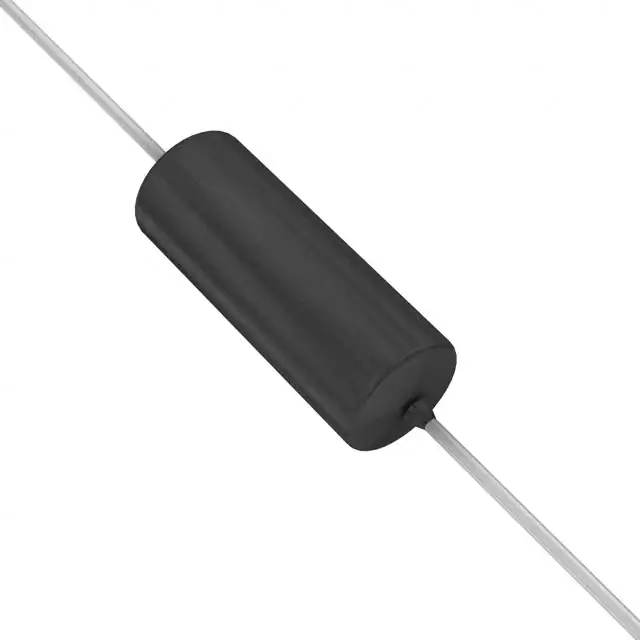
• Available in four case codes and capacitors and are
supplied with plastic-film insulation
• Terminals are solid, tinned nickel wire leads
• The military equivalent of the 150D is the M39003/01 (style
CSR13) which is qualified to MIL-PRF-39003/1
• Material categorization: for definitions of compliance
please see www.vishay.com/doc?99912
Note
* This datasheet provides information about parts that are
RoHS-compliant and / or parts that are non RoHS-compliant. For
example, parts with lead (Pb) terminations are not RoHS-compliant.
Please see the information / tables in this datasheet for details
ORDERING INFORMATION
150D
224
X0
006
A
2
T
E3
MODEL
CAPACITANCE
CAPACITANCE
TOLERANCE
DC VOLTAGE RATING
AT 85 °C
CASE
CODE
STYLE
NUMBER
PACKAGING
RoHSCOMPLIANT
This is expressed
in picofarads. The
first two digits are
the significant
figures. The third
is the number of
zeros to follow.
X0 = ± 20 %
X9 = ± 10 %
X5 = ± 5 % *
* Special order
This is expressed in
volts. To complete the
three-digit block,
zeros precede the
voltage rating.
See
Ratings
and Case
Codes
table
0 = no sleeve
2 = insulated
sleeve
B = bulk
T = tape
and reel
G = ammo
pack
E3 = 100 % tin
termination
(RoHS-compliant)
Blank = SnPb
termination
Revision: 08-Feb-2023
Document Number: 40015
1
For technical questions, contact: tantalum@vishay.com
THIS DOCUMENT IS SUBJECT TO CHANGE WITHOUT NOTICE. THE PRODUCTS DESCRIBED HEREIN AND THIS DOCUMENT
ARE SUBJECT TO SPECIFIC DISCLAIMERS, SET FORTH AT www.vishay.com/doc?91000
�150D
www.vishay.com
Vishay Sprague
DIMENSIONS in inches [millimeters]
1.500 ± 0.250
[38.10 ± 6.35]
1.500 ± 0.250
[38.10 ± 6.35]
L1
Positive lead
D
dia.
+
-
Solid tinned
nickel leads
CASE CODE
0.047 [1.19] max.
0.125 [3.18] max.
J
max.
D
L1
WITH INSULATING SLEEVE
(1)
J
(MAXIMUM)
LEAD SIZE
AWG NO.
NOMINAL DIAMETER
A
0.135 ± 0.016 [3.43 ± 0.41]
0.286 ± 0.031 [7.26 ± 0.79]
0.422 [10.720]
24
0.020 [0.51]
B
0.185 ± 0.016 [4.70 ± 0.41]
0.474 ± 0.031 [12.04 ± 0.79]
0.610 [15.490]
24
0.020 [0.51]
R
0.289 ± 0.016 [7.34 ± 0.41]
0.686 ± 0.031 [17.42 ± 0.79]
0.822 [20.880]
22
0.025 [0.64]
S
0.351 ± 0.016 [8.92 ± 0.41]
0.786 ± 0.031 [19.96 ± 0.79]
0.922 [23.420]
22
0.025 [0.64]
Note
(1) When a shrink-fitted insulation is used, it shall lap over the ends of the capacitor body
STANDARD RATINGS
CAPACITANCE
(μF)
0.22
0.27
0.33
0.39
0.47
0.56
0.68
0.82
1.0
1.2
1.5
1.8
2.2
2.7
3.3
3.9
4.7
5.6
6.8
8.2
10
12
15
18
22
27
33
39
CASE CODE
PART NUMBER
MAX. DCL
AT +25 °C
(μA)
6 VDC AT +85 °C, SURGE = 8 V; 4 VDC AT +125 °C, SURGE = 5 V
A
150D224(1)006A(2)(3)(4)
0.5
A
150D274(1)006A(2)(3)(4)
0.5
A
150D334(1)006A(2)(3)(4)
0.5
A
150D394(1)006A(2)(3)(4)
0.5
A
150D474(1)006A(2)(3)(4)
0.5
A
150D564(1)006A(2)(3)(4)
0.5
A
150D684(1)006A(2)(3)(4)
0.5
A
150D824(1)006A(2)(3)(4)
0.5
A
150D105(1)006A(2)(3)(4)
0.5
A
150D125(1)006A(2)(3)(4)
0.5
A
150D155(1)006A(2)(3)(4)
0.5
A
150D185(1)006A(2)(3)(4)
0.5
A
150D225(1)006A(2)(3)(4)
0.5
A
150D275(1)006A(2)(3)(4)
0.5
A
150D335(1)006A(2)(3)(4)
0.5
A
150D395(1)006A(2)(3)(4)
0.5
A
150D475(1)006A(2)(3)(4)
0.5
A
150D565(1)006A(2)(3)(4)
0.5
A
150D685(1)006A(2)(3)(4)
0.5
B
150D825(1)006B(2)(3)(4)
0.5
B
150D106(1)006B(2)(3)(4)
0.5
B
150D126(1)006B(2)(3)(4)
0.5
B
150D156(1)006B(2)(3)(4)
1.0
B
150D186(1)006B(2)(3)(4)
1.0
B
150D226(1)006B(2)(3)(4)
1.0
B
150D276(1)006B(2)(3)(4)
1.0
B
150D336(1)006B(2)(3)(4)
1.0
B
150D396(1)006B(2)(3)(4)
1.0
MAX. DF
AT +25 °C
120 Hz
(%)
2
2
2
2
2
2
2
2
2
4
4
4
4
4
4
4
4
4
6
6
6
6
6
6
6
6
6
6
Note
• Part number definitions:
(1) For 10 % tolerance specify “X9”; for 20 % specify “X0”; for 5 % “X5” (special order)
(2) Style number: 0 = no sleeve, 2 = insulated sleeve
(3) Packaging options: B = bulk, T = tape and reel, G = ammo pack
(4) Termination: E3 = 100 % tin, blank = SnPb
Revision: 08-Feb-2023
Document Number: 40015
2
For technical questions, contact: tantalum@vishay.com
THIS DOCUMENT IS SUBJECT TO CHANGE WITHOUT NOTICE. THE PRODUCTS DESCRIBED HEREIN AND THIS DOCUMENT
ARE SUBJECT TO SPECIFIC DISCLAIMERS, SET FORTH AT www.vishay.com/doc?91000
�150D
www.vishay.com
Vishay Sprague
STANDARD RATINGS
CAPACITANCE
(μF)
47
56
68
82
100
120
150
180
220
270
330
0.22
0.27
0.33
0.39
0.47
0.56
0.68
0.82
1.0
1.2
1.5
1.8
2.2
2.7
3.3
3.9
4.7
5.6
6.8
8.2
10
12
15
18
22
27
33
39
47
56
68
82
100
120
150
180
220
CASE CODE
PART NUMBER
MAX. DCL
AT +25 °C
(μA)
6 VDC AT +85 °C, SURGE = 8 V; 4 VDC AT +125 °C, SURGE = 5 V
B
150D476(1)006B(2)(3)(4)
2.0
B
150D566(1)006B(2)(3)(4)
2.0
R
150D686(1)006R(2)(3)(4)
3.0
R
150D826(1)006R(2)(3)(4)
3.0
R
150D107(1)006R(2)(3)(4)
3.0
R
150D127(1)006R(2)(3)(4)
3.0
R
150D157(1)006R(2)(3)(4)
6.0
R
150D187(1)006R(2)(3)(4)
6.0
S
150D227(1)006S(2)(3)(4)
6.0
S
150D277(1)006S(2)(3)(4)
6.0
S
150D337(1)006S(2)(3)(4)
10.0
10 VDC AT +85 °C, SURGE = 13 V; 7 VDC AT +125 °C, SURGE = 9 V
A
150D224(1)010A(2)(3)(4)
0.5
A
150D274(1)010A(2)(3)(4)
0.5
A
150D334(1)010A(2)(3)(4)
0.5
A
150D394(1)010A(2)(3)(4)
0.5
A
150D474(1)010A(2)(3)(4)
0.5
A
150D564(1)010A(2)(3)(4)
0.5
A
150D684(1)010A(2)(3)(4)
0.5
A
150D824(1)010A(2)(3)(4)
0.5
A
150D105(1)010A(2)(3)(4)
0.5
A
150D125(1)010A(2)(3)(4)
0.5
A
150D155(1)010A(2)(3)(4)
0.5
A
150D185(1)010A(2)(3)(4)
0.5
A
150D225(1)010A(2)(3)(4)
0.5
A
150D275(1)010A(2)(3)(4)
0.5
A
150D335(1)010A(2)(3)(4)
0.5
A
150D395(1)010A(2)(3)(4)
0.5
A
150D475(1)010A(2)(3)(4)
0.5
B
150D565(1)010B(2)(3)(4)
0.5
B
150D685(1)010B(2)(3)(4)
1.0
B
150D825(1)010B(2)(3)(4)
1.0
B
150D106(1)010B(2)(3)(4)
1.0
B
150D126(1)010B(2)(3)(4)
1.0
B
150D156(1)010B(2)(3)(4)
1.0
B
150D186(1)010B(2)(3)(4)
1.0
B
150D226(1)010B(2)(3)(4)
2.0
B
150D276(1)010B(2)(3)(4)
2.0
B
150D336(1)010B(2)(3)(4)
2.0
B
150D396(1)010B(2)(3)(4)
2.0
R
150D476(1)010R(2)(3)(4)
3.0
R
150D566(1)010R(2)(3)(4)
3.0
R
150D686(1)010R(2)(3)(4)
3.0
R
150D826(1)010R(2)(3)(4)
3.0
R
150D107(1)010R(2)(3)(4)
6.0
R
150D127(1)010R(2)(3)(4)
6.0
S
150D157(1)010S(2)(3)(4)
10.0
S
150D187(1)010S(2)(3)(4)
10.0
S
150D227(1)010S(2)(3)(4)
10.0
MAX. DF
AT +25 °C
120 Hz
(%)
6
6
6
6
6
6
6
6
8
8
8
2
2
2
2
2
2
2
2
2
4
4
4
4
4
4
4
4
4
6
6
6
6
6
6
6
6
6
6
6
6
6
6
6
6
6
6
8
Note
• Part number definitions:
(1) For 10 % tolerance specify “X9”; for 20 % specify “X0”; for 5 % “X5” (special order)
(2) Style number: 0 = no sleeve, 2 = insulated sleeve
(3) Packaging options: B = bulk, T = tape and reel, G = ammo pack
(4) Termination: E3 = 100 % tin, blank = SnPb
Revision: 08-Feb-2023
Document Number: 40015
3
For technical questions, contact: tantalum@vishay.com
THIS DOCUMENT IS SUBJECT TO CHANGE WITHOUT NOTICE. THE PRODUCTS DESCRIBED HEREIN AND THIS DOCUMENT
ARE SUBJECT TO SPECIFIC DISCLAIMERS, SET FORTH AT www.vishay.com/doc?91000
�150D
www.vishay.com
Vishay Sprague
STANDARD RATINGS
CAPACITANCE
(μF)
0.22
0.27
0.33
0.39
0.47
0.56
0.68
0.82
1.0
1.2
1.5
1.8
2.2
2.7
3.3
3.9
4.7
5.6
6.8
8.2
10
12
15
18
22
27
33
39
47
56
68
82
100
120
150
0.033
0.039
0.047
0.056
0.068
0.082
0.10
0.12
0.15
0.18
0.22
0.27
0.33
CASE CODE
PART NUMBER
MAX. DCL
AT +25 °C
(μA)
15 VDC AT +85 °C, SURGE = 20 V; 10 VDC AT +125 °C, SURGE = 12 V
A
150D224(1)015A(2)(3)(4)
0.5
A
150D274(1)015A(2)(3)(4)
0.5
A
150D334(1)015A(2)(3)(4)
0.5
A
150D394(1)015A(2)(3)(4)
0.5
A
150D474(1)015A(2)(3)(4)
0.5
A
150D564(1)015A(2)(3)(4)
0.5
A
150D684(1)015A(2)(3)(4)
0.5
A
150D824(1)015A(2)(3)(4)
0.5
A
150D105(1)015A(2)(3)(4)
0.5
A
150D125(1)015A(2)(3)(4)
0.5
A
150D155(1)015A(2)(3)(4)
0.5
A
150D185(1)015A(2)(3)(4)
0.5
A
150D225(1)015A(2)(3)(4)
0.5
A
150D275(1)015A(2)(3)(4)
0.5
A
150D335(1)015A(2)(3)(4)
0.5
B
150D395(1)015B(2)(3)(4)
0.5
B
150D475(1)015B(2)(3)(4)
1.0
B
150D565(1)015B(2)(3)(4)
1.0
B
150D685(1)015B(2)(3)(4)
1.0
B
150D825(1)015B(2)(3)(4)
1.0
B
150D106(1)015B(2)(3)(4)
1.0
B
150D126(1)015B(2)(3)(4)
1.0
B
150D156(1)015B(2)(3)(4)
2.0
B
150D186(1)015B(2)(3)(4)
2.0
B
150D226(1)015B(2)(3)(4)
3.0
R
150D276(1)015R(2)(3)(4)
3.0
R
150D336(1)015R(2)(3)(4)
3.0
R
150D396(1)015R(2)(3)(4)
3.0
R
150D476(1)015R(2)(3)(4)
6.0
R
150D566(1)015R(2)(3)(4)
6.0
R
150D686(1)015R(2)(3)(4)
6.0
S
150D826(1)015S(2)(3)(4)
6.0
S
150D107(1)015S(2)(3)(4)
6.0
S
150D127(1)015S(2)(3)(4)
6.0
S
150D157(1)015S(2)(3)(4)
10.0
20 VDC AT +85 °C, SURGE = 26 V; 13 VDC AT +125 °C, SURGE = 16 V
A
150D333(1)020A(2)(3)(4)
0.1
A
150D393(1)020A(2)(3)(4)
0.1
A
150D473(1)020A(2)(3)(4)
0.1
A
150D563(1)020A(2)(3)(4)
0.1
A
150D683(1)020A(2)(3)(4)
0.1
A
150D823(1)020A(2)(3)(4)
0.1
A
150D104(1)020A(2)(3)(4)
0.5
A
150D124(1)020A(2)(3)(4)
0.5
A
150D154(1)020A(2)(3)(4)
0.5
A
150D184(1)020A(2)(3)(4)
0.5
A
150D224(1)020A(2)(3)(4)
0.5
A
150D274(1)020A(2)(3)(4)
0.5
A
150D334(1)020A(2)(3)(4)
0.5
MAX. DF
AT +25 °C
120 Hz
(%)
2
2
2
2
2
2
2
2
2
4
4
4
4
4
4
4
4
4
6
6
6
6
6
6
6
6
6
6
6
6
6
6
6
6
6
2
2
2
2
2
2
2
2
2
2
2
2
2
Note
• Part number definitions:
(1) For 10 % tolerance specify “X9”; for 20 % specify “X0”; for 5 % “X5” (special order)
(2) Style number: 0 = no sleeve, 2 = insulated sleeve
(3) Packaging options: B = bulk, T = tape and reel, G = ammo pack
(4) Termination: E3 = 100 % tin, blank = SnPb
Revision: 08-Feb-2023
Document Number: 40015
4
For technical questions, contact: tantalum@vishay.com
THIS DOCUMENT IS SUBJECT TO CHANGE WITHOUT NOTICE. THE PRODUCTS DESCRIBED HEREIN AND THIS DOCUMENT
ARE SUBJECT TO SPECIFIC DISCLAIMERS, SET FORTH AT www.vishay.com/doc?91000
�150D
www.vishay.com
Vishay Sprague
STANDARD RATINGS
CAPACITANCE
(μF)
0.39
0.47
0.56
0.68
0.82
1.0
1.2
1.5
1.8
2.2
2.7
3.3
3.9
4.7
5.6
6.8
8.2
10
12
15
18
22
27
33
39
47
56
68
82
100
1.2
1.5
1.8
4.7
5.6
6.8
8.2
10
15
33
68
100
0.033
0.039
0.047
0.056
0.068
CASE CODE
PART NUMBER
MAX. DCL
AT +25 °C
(μA)
20 VDC AT +85 °C, SURGE = 26 V; 13 VDC AT +125 °C, SURGE = 16 V
A
150D394(1)020A(2)(3)(4)
0.5
A
150D474(1)020A(2)(3)(4)
0.5
A
150D564(1)020A(2)(3)(4)
0.5
A
150D684(1)020A(2)(3)(4)
0.5
A
150D824(1)020A(2)(3)(4)
0.5
A
150D105(1)020A(2)(3)(4)
0.5
A
150D125(1)020A(2)(3)(4)
0.5
A
150D155(1)020A(2)(3)(4)
0.5
A
150D185(1)020A(2)(3)(4)
0.5
A
150D225(1)020A(2)(3)(4)
0.5
B
150D275(1)020B(2)(3)(4)
0.5
B
150D335(1)020B(2)(3)(4)
0.5
B
150D395(1)020B(2)(3)(4)
1.0
B
150D475(1)020B(2)(3)(4)
1.0
B
150D565(1)020B(2)(3)(4)
1.0
B
150D685(1)020B(2)(3)(4)
1.0
B
150D825(1)020B(2)(3)(4)
1.0
B
150D106(1)020B(2)(3)(4)
1.0
B
150D126(1)020B(2)(3)(4)
1.0
B
150D156(1)020B(2)(3)(4)
2.0
R
150D186(1)020R(2)(3)(4)
3.0
R
150D226(1)020R(2)(3)(4)
3.0
R
150D276(1)020R(2)(3)(4)
3.0
R
150D336(1)020R(2)(3)(4)
3.0
R
150D396(1)020R(2)(3)(4)
3.0
R
150D476(1)020R(2)(3)(4)
6.0
S
150D566(1)020S(2)(3)(4)
6.0
S
150D686(1)020S(2)(3)(4)
6.0
S
150D826(1)020S(2)(3)(4)
6.0
S
150D107(1)020S(2)(3)(4)
10.0
25 VDC AT +85 °C, SURGE = 32 V; 17 VDC AT +125 °C, SURGE = 21 V
A
150D125(1)025A(2)(3)(4)
0.5
A
150D155(1)025A(2)(3)(4)
0.5
A
150D185(1)025A(2)(3)(4)
0.5
B
150D475(1)025B(2)(3)(4)
1.2
B
150D565(1)025B(2)(3)(4)
1.4
B
150D685(1)025B(2)(3)(4)
1.7
B
150D825(1)025B(2)(3)(4)
2.1
B
150D106(1)025B(2)(3)(4)
2.5
B
150D156(1)025B(2)(3)(4)
3.8
R
150D336(1)025R(2)(3)(4)
8.3
S
150D686(1)025S(2)(3)(4)
17
S
150D107(1)025S(2)(3)(4)
25
35 VDC AT +85 °C, SURGE = 46 V; 23 VDC AT +125 °C, SURGE = 28 V
A
150D333(1)035A(2)(3)(4)
0.1
A
150D393(1)035A(2)(3)(4)
0.1
A
150D473(1)035A(2)(3)(4)
0.1
A
150D563(1)035A(2)(3)(4)
0.1
A
150D683(1)035A(2)(3)(4)
0.1
MAX. DF
AT +25 °C
120 Hz
(%)
2
2
2
2
2
2
4
4
4
4
4
4
4
4
4
6
6
6
6
6
6
6
6
6
6
6
6
6
6
6
4
4
4
4
4
4
4
6
6
6
6
6
2
2
2
2
2
Note
• Part number definitions:
(1) For 10 % tolerance specify “X9”; for 20 % specify “X0”; for 5 % “X5” (special order)
(2) Style number: 0 = no sleeve, 2 = insulated sleeve
(3) Packaging options: B = bulk, T = tape and reel, G = ammo pack
(4) Termination: E3 = 100 % tin, blank = SnPb
Revision: 08-Feb-2023
Document Number: 40015
5
For technical questions, contact: tantalum@vishay.com
THIS DOCUMENT IS SUBJECT TO CHANGE WITHOUT NOTICE. THE PRODUCTS DESCRIBED HEREIN AND THIS DOCUMENT
ARE SUBJECT TO SPECIFIC DISCLAIMERS, SET FORTH AT www.vishay.com/doc?91000
�150D
www.vishay.com
Vishay Sprague
STANDARD RATINGS
CAPACITANCE
(μF)
0.082
0.10
0.12
0.15
0.18
0.22
0.27
0.33
0.39
0.47
0.56
0.68
0.82
1.0
1.2
1.5
1.8
2.2
2.7
3.3
3.9
4.7
5.6
6.8
8.2
10
12
15
18
22
27
33
39
47
0.056
0.068
0.082
0.10
0.12
0.15
0.18
0.22
0.27
0.33
0.39
0.47
0.56
0.68
CASE CODE
PART NUMBER
MAX. DCL
AT +25 °C
(μA)
35 VDC AT +85 °C, SURGE = 46 V; 23 VDC AT +125 °C, SURGE = 28 V
A
150D823(1)035A(2)(3)(4)
0.1
A
150D104(1)035A(2)(3)(4)
0.5
A
150D124(1)035A(2)(3)(4)
0.5
A
150D154(1)035A(2)(3)(4)
0.5
A
150D184(1)035A(2)(3)(4)
0.5
A
150D224(1)035A(2)(3)(4)
0.5
A
150D274(1)035A(2)(3)(4)
0.5
A
150D334(1)035A(2)(3)(4)
0.5
A
150D394(1)035A(2)(3)(4)
0.5
A
150D474(1)035A(2)(3)(4)
0.5
A
150D564(1)035A(2)(3)(4)
0.5
A
150D684(1)035A(2)(3)(4)
0.5
A
150D824(1)035A(2)(3)(4)
0.5
A
150D105(1)035A(2)(3)(4)
0.5
B
150D125(1)035B(2)(3)(4)
0.5
B
150D155(1)035B(2)(3)(4)
0.5
B
150D185(1)035B(2)(3)(4)
0.5
B
150D225(1)035B(2)(3)(4)
1.0
B
150D275(1)035B(2)(3)(4)
1.0
B
150D335(1)035B(2)(3)(4)
1.0
B
150D395(1)035B(2)(3)(4)
1.0
B
150D475(1)035B(2)(3)(4)
1.0
B
150D565(1)035B(2)(3)(4)
1.0
B
150D685(1)035B(2)(3)(4)
2.0
R
150D825(1)035R(2)(3)(4)
3.0
R
150D106(1)035R(2)(3)(4)
3.0
R
150D126(1)035R(2)(3)(4)
3.0
R
150D156(1)035R(2)(3)(4)
3.0
R
150D186(1)035R(2)(3)(4)
3.0
R
150D226(1)035R(2)(3)(4)
6.0
S
150D276(1)035S(2)(3)(4)
6.0
S
150D336(1)035S(2)(3)(4)
6.0
S
150D396(1)035S(2)(3)(4)
6.0
S
150D476(1)035S(2)(3)(4)
10.0
50 VDC AT +85 °C, SURGE = 65 V; 33 VDC AT +125 °C, SURGE = 40 V
A
150D563(1)050A(2)(3)(4)
0.1
A
150D683(1)050A(2)(3)(4)
0.1
A
150D823(1)050A(2)(3)(4)
0.1
A
150D104(1)050A(2)(3)(4)
0.5
A
150D124(1)050A(2)(3)(4)
0.5
A
150D154(1)050A(2)(3)(4)
0.5
A
150D184(1)050A(2)(3)(4)
0.5
A
150D224(1)050A(2)(3)(4)
0.5
A
150D274(1)050A(2)(3)(4)
0.5
A
150D334(1)050A(2)(3)(4)
0.5
A
150D394(1)050A(2)(3)(4)
0.5
A
150D474(1)050A(2)(3)(4)
0.5
A
150D564(1)050A(2)(3)(4)
0.5
A
150D684(1)050A(2)(3)(4)
0.5
MAX. DF
AT +25 °C
120 Hz
(%)
2
2
2
2
2
2
2
2
2
2
2
2
2
2
4
4
4
4
4
4
4
4
4
4
4
4
4
4
4
4
4
4
4
4
2
2
2
2
2
2
2
2
2
2
2
2
2
2
Note
• Part number definitions:
(1) For 10 % tolerance specify “X9”; for 20 % specify “X0”; for 5 % “X5” (special order)
(2) Style number: 0 = no sleeve, 2 = insulated sleeve
(3) Packaging options: B = bulk, T = tape and reel, G = ammo pack
(4) Termination: E3 = 100 % tin, blank = SnPb
Revision: 08-Feb-2023
Document Number: 40015
6
For technical questions, contact: tantalum@vishay.com
THIS DOCUMENT IS SUBJECT TO CHANGE WITHOUT NOTICE. THE PRODUCTS DESCRIBED HEREIN AND THIS DOCUMENT
ARE SUBJECT TO SPECIFIC DISCLAIMERS, SET FORTH AT www.vishay.com/doc?91000
�150D
www.vishay.com
Vishay Sprague
STANDARD RATINGS
CAPACITANCE
(μF)
0.82
1.0
1.2
1.5
1.8
2.2
2.7
3.3
3.9
4.7
5.6
6.8
8.2
10
12
15
18
22
0.10
0.12
0.15
0.18
0.22
0.27
0.33
0.39
0.47
0.56
0.68
1.0
2.2
4.7
5.6
6.8
8.2
10
12
15
18
22
0.033
0.039
0.047
0.056
0.068
0.082
0.10
CASE CODE
PART NUMBER
MAX. DCL
AT +25 °C
(μA)
50 VDC AT +85 °C, SURGE = 65 V; 33 VDC AT +125 °C, SURGE = 40 V
A
150D824(1)050A(2)(3)(4)
0.5
A
150D105(1)050A(2)(3)(4)
0.5
B
150D125(1)050B(2)(3)(4)
0.5
B
150D155(1)050B(2)(3)(4)
0.5
B
150D185(1)050B(2)(3)(4)
0.5
B
150D225(1)050B(2)(3)(4)
1.0
B
150D275(1)050B(2)(3)(4)
1.0
B
150D335(1)050B(2)(3)(4)
2.0
B
150D395(1)050B(2)(3)(4)
2.0
B
150D475(1)050B(2)(3)(4)
3.0
R
150D565(1)050R(2)(3)(4)
3.0
R
150D685(1)050R(2)(3)(4)
3.0
R
150D825(1)050R(2)(3)(4)
3.0
R
150D106(1)050R(2)(3)(4)
3.0
R
150D126(1)050R(2)(3)(4)
3.0
R
150D156(1)050R(2)(3)(4)
6.0
R
150D186(1)050R(2)(3)(4)
6.0
S
150D226(1)050S(2)(3)(4)
6.0
60 VDC AT +85 °C, SURGE = 78 V; 40 VDC AT +125 °C, SURGE = 49 V
A
150D104(1)060A(2)(3)(4)
0.5
A
150D124(1)060A(2)(3)(4)
0.5
A
150D154(1)060A(2)(3)(4)
0.5
A
150D184(1)060A(2)(3)(4)
0.5
A
150D224(1)060A(2)(3)(4)
0.5
A
150D274(1)060A(2)(3)(4)
0.5
A
150D334(1)060A(2)(3)(4)
0.5
A
150D394(1)060A(2)(3)(4)
0.5
A
150D474(1)060A(2)(3)(4)
0.5
A
150D564(1)060A(2)(3)(4)
0.5
A
150D684(1)060A(2)(3)(4)
0.5
B
150D105(1)060B(2)(3)(4)
0.5
B
150D225(1)060B(2)(3)(4)
1.0
R
150D475(1)060R(2)(3)(4)
3.0
R
150D565(1)060R(2)(3)(4)
3.0
R
150D685(1)060R(2)(3)(4)
4.0
R
150D825(1)060R(2)(3)(4)
5.0
R
150D106(1)060R(2)(3)(4)
6.0
S
150D126(1)060S(2)(3)(4)
6.0
S
150D156(1)060S(2)(3)(4)
9.0
S
150D186(1)060S(2)(3)(4)
10.0
S
150D226(1)060S(2)(3)(4)
12.0
75 VDC AT +85 °C, SURGE = 98 V; 50 VDC AT +125 °C, SURGE = 64 V
A
150D333(1)075A(2)(3)(4)
0.5
A
150D393(1)075A(2)(3)(4)
0.5
A
150D473(1)075A(2)(3)(4)
0.5
A
150D563(1)075A(2)(3)(4)
0.5
A
150D683(1)075A(2)(3)(4)
0.5
A
150D823(1)075A(2)(3)(4)
0.5
A
150D104(1)075A(2)(3)(4)
0.5
MAX. DF
AT +25 °C
120 Hz
(%)
2
2
4
4
4
4
4
4
4
4
4
4
4
4
4
4
4
4
4.0
4.0
4.0
4.0
4.0
4.0
4.0
4.0
4.0
4.0
4.0
4.0
4.0
6.0
6.0
6.0
6.0
6.0
6.0
6.0
6.0
6.0
2
2
2
2
2
2
2
Note
• Part number definitions:
(1) For 10 % tolerance specify “X9”; for 20 % specify “X0”; for 5 % “X5” (special order)
(2) Style number: 0 = no sleeve, 2 = insulated sleeve
(3) Packaging options: B = bulk, T = tape and reel, G = ammo pack
(4) Termination: E3 = 100 % tin, blank = SnPb
Revision: 08-Feb-2023
Document Number: 40015
7
For technical questions, contact: tantalum@vishay.com
THIS DOCUMENT IS SUBJECT TO CHANGE WITHOUT NOTICE. THE PRODUCTS DESCRIBED HEREIN AND THIS DOCUMENT
ARE SUBJECT TO SPECIFIC DISCLAIMERS, SET FORTH AT www.vishay.com/doc?91000
�150D
www.vishay.com
Vishay Sprague
STANDARD RATINGS
CAPACITANCE
(μF)
0.12
0.15
0.18
0.22
0.27
0.33
0.39
0.47
0.56
0.68
0.82
1.0
1.2
1.5
1.8
2.2
2.7
3.3
3.9
4.7
5.6
6.8
8.2
10
12
15
0.033
0.039
0.047
0.056
0.068
0.082
0.10
0.12
0.15
0.18
0.22
0.27
0.33
0.39
0.47
0.56
0.68
0.82
1.0
1.2
1.5
1.8
2.2
CASE CODE
PART NUMBER
MAX. DCL
AT +25 °C
(μA)
75 VDC AT +85 °C, SURGE = 98 V; 50 VDC AT +125 °C, SURGE = 64 V
A
150D124(1)075A(2)(3)(4)
0.5
A
150D154(1)075A(2)(3)(4)
0.5
A
150D184(1)075A(2)(3)(4)
0.5
A
150D224(1)075A(2)(3)(4)
0.5
A
150D274(1)075A(2)(3)(4)
0.5
A
150D334(1)075A(2)(3)(4)
0.5
A
150D394(1)075A(2)(3)(4)
0.5
A
150D474(1)075A(2)(3)(4)
0.5
A
150D564(1)075A(2)(3)(4)
0.5
A
150D684(1)075A(2)(3)(4)
0.5
B
150D824(1)075B(2)(3)(4)
0.5
B
150D105(1)075B(2)(3)(4)
0.5
B
150D125(1)075B(2)(3)(4)
0.5
B
150D155(1)075B(2)(3)(4)
1.0
B
150D185(1)075B(2)(3)(4)
1.0
B
150D225(1)075B(2)(3)(4)
1.0
B
150D275(1)075B(2)(3)(4)
1.0
B
150D335(1)075B(2)(3)(4)
2.0
B
150D395(1)075B(2)(3)(4)
2.0
R
150D475(1)075R(2)(3)(4)
4.0
R
150D565(1)075R(2)(3)(4)
4.0
R
150D685(1)075R(2)(3)(4)
6.0
R
150D825(1)075R(2)(3)(4)
6.0
R
150D106(1)075R(2)(3)(4)
8.0
S
150D126(1)075S(2)(3)(4)
10.0
S
150D156(1)075S(2)(3)(4)
12.0
100 VDC AT +85 °C, SURGE = 130 V; 67 VDC AT +125 °C, SURGE = 86 V
A
150D333(1)100A(2)(3)(4)
0.5
A
150D393(1)100A(2)(3)(4)
0.5
A
150D473(1)100A(2)(3)(4)
0.5
A
150D563(1)100A(2)(3)(4)
0.5
A
150D683(1)100A(2)(3)(4)
0.5
A
150D823(1)100A(2)(3)(4)
0.5
A
150D104(1)100A(2)(3)(4)
0.5
A
150D124(1)100A(2)(3)(4)
0.5
A
150D154(1)100A(2)(3)(4)
0.5
A
150D184(1)100A(2)(3)(4)
0.5
A
150D224(1)100A(2)(3)(4)
0.5
A
150D274(1)100A(2)(3)(4)
0.5
A
150D334(1)100A(2)(3)(4)
0.5
A
150D394(1)100A(2)(3)(4)
0.5
A
150D474(1)100A(2)(3)(4)
0.5
A
150D564(1)100A(2)(3)(4)
0.5
B
150D684(1)100B(2)(3)(4)
0.5
B
150D824(1)100B(2)(3)(4)
0.5
B
150D105(1)100B(2)(3)(4)
0.5
B
150D125(1)100B(2)(3)(4)
0.5
B
150D155(1)100B(2)(3)(4)
0.6
B
150D185(1)100B(2)(3)(4)
0.6
B
150D225(1)100B(2)(3)(4)
0.6
MAX. DF
AT +25 °C
120 Hz
(%)
2
2
2
2
2
2
2
2
2
2
2
2
4
4
4
4
4
4
4
4
4
4
4
4
4
4
2
2
2
2
2
2
2
2
2
2
2
2
2
2
2
2
2
2
2
3
3
3
3
Note
• Part number definitions:
(1) For 10 % tolerance specify “X9”; for 20 % specify “X0”; for 5 % “X5” (special order)
(2) Style number: 0 = no sleeve, 2 = insulated sleeve
(3) Packaging options: B = bulk, T = tape and reel, G = ammo pack
(4) Termination: E3 = 100 % tin, blank = SnPb
Revision: 08-Feb-2023
Document Number: 40015
8
For technical questions, contact: tantalum@vishay.com
THIS DOCUMENT IS SUBJECT TO CHANGE WITHOUT NOTICE. THE PRODUCTS DESCRIBED HEREIN AND THIS DOCUMENT
ARE SUBJECT TO SPECIFIC DISCLAIMERS, SET FORTH AT www.vishay.com/doc?91000
�150D
www.vishay.com
Vishay Sprague
STANDARD RATINGS
CAPACITANCE
(μF)
CASE CODE
PART NUMBER
MAX. DF
AT +25 °C
120 Hz
(%)
MAX. DCL
AT +25 °C
(μA)
100 VDC AT +85 °C, SURGE = 130 V; 67 VDC AT +125 °C, SURGE = 86 V
B
150D275(1)100B(2)(3)(4)
0.6
R
150D335(1)100R(2)(3)(4)
2.5
R
150D395(1)100R(2)(3)(4)
3.0
R
150D475(1)100R(2)(3)(4)
4.0
R
150D565(1)100R(2)(3)(4)
4.0
R
150D685(1)100R(2)(3)(4)
6.0
S
150D825(1)100S(2)(3)(4)
6.0
S
150D106(1)100S(2)(3)(4)
6.0
125 VDC AT +85 °C, SURGE = 140 V; 82 VDC AT +125 °C, SURGE = 94 V
A
150D273(1)125A(2)(3)(4)
1.0
A
150D333(1)125A(2)(3)(4)
1.0
A
150D393(1)125A(2)(3)(4)
1.0
A
150D473(1)125A(2)(3)(4)
1.0
A
150D563(1)125A(2)(3)(4)
1.0
A
150D683(1)125A(2)(3)(4)
1.0
A
150D823(1)125A(2)(3)(4)
1.0
A
150D104(1)125A(2)(3)(4)
1.0
A
150D124(1)125A(2)(3)(4)
1.0
A
150D154(1)125A(2)(3)(4)
1.0
A
150D184(1)125A(2)(3)(4)
1.0
A
150D224(1)125A(2)(3)(4)
1.0
A
150D274(1)125A(2)(3)(4)
1.0
A
150D334(1)125A(2)(3)(4)
1.0
A
150D394(1)125A(2)(3)(4)
1.5
A
150D474(1)125A(2)(3)(4)
1.5
B
150D564(1)125B(2)(3)(4)
1.6
B
150D684(1)125B(2)(3)(4)
1.8
B
150D824(1)125B(2)(3)(4)
2.0
B
150D105(1)125B(2)(3)(4)
2.0
B
150D125(1)125B(2)(3)(4)
2.0
B
150D155(1)125B(2)(3)(4)
2.0
B
150D185(1)125B(2)(3)(4)
2.0
B
150D225(1)125B(2)(3)(4)
2.0
2.7
3.3
3.9
4.7
5.6
6.8
8.2
10
0.027
0.033
0.039
0.047
0.056
0.068
0.082
0.10
0.12
0.15
0.18
0.22
0.27
0.33
0.39
0.47
0.56
0.68
0.82
1.0
1.2
1.5
1.8
2.2
3
3
3
3
3
3
3
3
2
2
2
2
2
2
2
2
2
2
2
2
2
2
2
2
2
2
2
2
3
3
3
3
Note
• Part number definitions:
(1) For 10 % tolerance specify “X9”; for 20 % specify “X0”; for 5 % “X5” (special order)
(2) Style number: 0 = no sleeve, 2 = insulated sleeve
(3) Packaging options: B = bulk, T = tape and reel, G = ammo pack
(4) Termination: E3 = 100 % tin, blank = SnPb
TAPE AND REEL PACKAGING in inches [millimeters]
Meets EIA standard RS-296
“A”
Tape
spacing
13.0 [330.2]
Standard reel
B
1.126 to 3.07
[28.6 to 78.0]
A
I. D. reel hub
Component
spacing
1.374 to 3.626
[34.9 to 92.1]
0.031 [0.79] max.
Off center (1. a)
0.625 ± 0.0062 dia.
[15.88 ± 1.575]
Thru hole
Label (4. a)
Revision: 08-Feb-2023
0.125 [3.18] max.
0.250 [6.35] (3. b)
“A”
0.750 [19.05]
Section “A” - “A”
0.031 [0.79] (3. f)
Both sides (3. f)
Document Number: 40015
9
For technical questions, contact: tantalum@vishay.com
THIS DOCUMENT IS SUBJECT TO CHANGE WITHOUT NOTICE. THE PRODUCTS DESCRIBED HEREIN AND THIS DOCUMENT
ARE SUBJECT TO SPECIFIC DISCLAIMERS, SET FORTH AT www.vishay.com/doc?91000
�150D
www.vishay.com
Vishay Sprague
STANDARD PACKAGING QUANTITY AND DIMENSIONS in inches [millimeters]
CASE
CODE
COMPONENT SPACING
A
A
B
R
S
0.200 ± 0.015
[5.08 ± 0.38]
0.200 ± 0.015
[5.08 ± 0.38]
0.400 ± 0.015
[10.16 ± 0.38]
0.400 ± 0.015
[10.16 ± 0.38]
TAPE AND REEL
TAPE SPACING
UNITS PER REEL
B
2.500 ± 0.062
1000
[63.5 ± 1.57]
2.500 ± 0.062
1000
[63.5 ± 1.57]
2.875 ± 0.062
500
[73.03 ± 1.57]
2.875 ± 0.062
500
[73.03 ± 1.57]
AMMO PACK
TAPE SPACING
UNITS PER BOX
B
2.063 ± 0.073
500
[53 ± 2]
2.063 ± 0.073
500
[53 ± 2]
2.063 ± 0.073
250
[53 ± 2]
2.063 ± 0.073
250
[53 ± 2]
STANDARD REEL PACKAGING INFORMATION
1. Component Leads
a. Component leads shall not be bent beyond 0.047"
[1.19 mm] maximum from their nominal position when
measured from the leading edge of the component lead
at the inside tape edge and at the lead egress from the
component.
b. The “C” dimension shall be governed by the overall
length of the reel packaged component. The distance
between flanges shall be 0.125" to 0.250" [3.18 mm to
6.35 mm] greater than the overall component length.
2. Orientation
All polarized components must be oriented to one
direction. The cathode lead tape shall be a color and the
anode lead tape shall be white.
3. Reeling
a. Components on any reel shall not represent more than
two date codes when date code identification is required.
b. Component leads shall be positioned between pairs of
0.250" [6.35 mm] tape.
c. The disposable reels have hubs and corrugated
fibreboard flanges and core or equivalent.
d. A minimum of 12.0" [304.8 mm] leader of tape shall be
provided before the first and after the last component on
the reel.
e. 50 lb or 60 lb. Kraft paper must be wound between layer
of components as far as necessary for component
protection. Width of paper to be 0.062" to 0.250"
[1.57 mm to 6.35 mm] less than the “C” dimension
of the reel. Solid-electrolyte TANTALEX capacitors
hermetically-sealed, axial-lead.
f. A row of components must be centered between tapes
± 0.047" [1.19 mm]. In addition, individual components
may deviate from center of component row ± 0.031"
[0.79 mm].
g. Staples shall not be used for splicing. Not more than
4 layers of tape shall be used in any splice area and no
tape shall be offset from another by more than 0.031"
[0.79 mm] non-cumulative. Tape splices shall overlap at
least 6.0" [152.4 mm] for butt joints and at least 3.0"
[76.2 mm] for lap joints and shall not be weaker than
unspliced tape. Universal splicing clips may also be used.
h. Quantity per reel shall be controlled so that tape
components and cover shall not extend beyond the
smallest dimension of the flange (either across flats or
diameter). Once the quantity per reel for each part
number has been established, future orders for that part
number shall be packaged in that quantity. When order or
release quantity is less than the established quantity, a
standard commercial pack is to be used.
i. A maximum of 0.25 % of the components per reel
quantity may be missing without consecutive missing
components.
j. Adequate protection must be provided to prevent
physical damage to both reel and components during
shipment and storage.
4. Marking
Minimum reel and carton marking shall consist of the
following: customer part number, purchase order no.,
quantity, package date, manufacturer’s name, electrical
value, date code, Vishay Sprague part number and
country of origin.
PRODUCT INFORMATION
Mounting of Through Hole Components
www.vishay.com/doc?40108
Solid Tantalum Capacitors (With MnO2 Electrolyte) Voltage Derating
www.vishay.com/doc?40246
SELECTOR GUIDES
Selector Guide
www.vishay.com/doc?49054
FAQ
Frequently Asked Questions
Revision: 08-Feb-2023
www.vishay.com/doc?40110
Document Number: 40015
10
For technical questions, contact: tantalum@vishay.com
THIS DOCUMENT IS SUBJECT TO CHANGE WITHOUT NOTICE. THE PRODUCTS DESCRIBED HEREIN AND THIS DOCUMENT
ARE SUBJECT TO SPECIFIC DISCLAIMERS, SET FORTH AT www.vishay.com/doc?91000
�150D
www.vishay.com
Vishay Sprague
TYPICAL CURVES AT +25 °C, IMPEDANCE AND ESR VS. FREQUENCY
Axis Title
Axis Title
Impedance
ESR
10000
10
120 μF, 10 V
1000
180 μF, 6 V
100
0.1
2nd line
Impedance / ESR (Ω)
330 μF, 6 V
1st line
2nd line
220 μF, 10 V
1000
1
120 μF, 10 V
100
0.1
220 μF, 10 V
330 μF, 6 V
0.01
100
1K
10K
100K
1M
10
10M
0.01
100
1K
10K
Frequency (Hz)
10000
10
68 μF, 15 V
100
2nd line
Impedance / ESR (Ω)
1000
0.1
100 μF, 20 V
1
10K
100K
100
1M
10
10M
0.01
100
1K
10
1M
10
10M
1000
100
18 μF, 50 V
10000
22 μF, 50 V
1000
1
1st line
2nd line
47 μF, 35 V
0.1
Impedance
ESR
18 μF, 50 V
2nd line
Impedance / ESR (Ω)
Impedance
ESR
1
0.1
100
22 μF, 50 V
47 μF, 35 V
0.01
10K
100K
Frequency (Hz)
Revision: 08-Feb-2023
100K
Axis Title
10000
1st line
2nd line
2nd line
Impedance / ESR (Ω)
22 μF, 35 V
10K
Frequency (Hz)
Axis Title
10
1K
1000
0.1
Frequency (Hz)
100
10000
100 μF, 20 V
0.01
22 μF, 35 V
10
10M
47 μF, 20 V
150 μF, 15 V
1K
Impedance
ESR
47 μF, 20 V
1st line
2nd line
2nd line
Impedance / ESR (Ω)
150 μF, 15 V
100
1M
Axis Title
Impedance
ESR
68 μF, 15 V
100K
Frequency (Hz)
Axis Title
10
1
10000
1st line
2nd line
2nd line
Impedance / ESR (Ω)
180 μF, 6 V
1
Impedance
ESR
1st line
2nd line
10
1M
10
10M
0.01
100
1K
10K
100K
1M
10
10M
Frequency (Hz)
Document Number: 40015
11
For technical questions, contact: tantalum@vishay.com
THIS DOCUMENT IS SUBJECT TO CHANGE WITHOUT NOTICE. THE PRODUCTS DESCRIBED HEREIN AND THIS DOCUMENT
ARE SUBJECT TO SPECIFIC DISCLAIMERS, SET FORTH AT www.vishay.com/doc?91000
�150D
www.vishay.com
Vishay Sprague
PERFORMANCE CHARACTERISTICS
1.
Operating Temperature: capacitors are designed to
operate over the temperature range of -55 °C to
+85 °C with no derating.
6.
Dissipation Factor: the dissipation factor,
determined from the expression 2πfCR, shall not
exceed values listed in the Standard Ratings table.
1.1
Capacitors may be operated up to +125 °C with
voltage derating to two-thirds the +85 °C rating.
6.1
Measurements shall be made by the bridge method
at, or referred to, a frequency of 1000 Hz and a
temperature of +25 °C.
7.
Leakage Current: capacitors shall be stabilized at
the rated temperature for 30 min. Rated voltage shall
be applied to capacitors for 5 min using a steady
source of power (such as a regulated power supply)
with 1000 Ω resistor connected in series with the
capacitor under test to limit the charging current.
Leakage current shall then be measured.
+85 °C RATING
WORKING
VOLTAGE
(V)
3.
3.1
3.2
4.
4.1
5.
SURGE
VOLTAGE
(V)
WORKING
VOLTAGE
(V)
SURGE
VOLTAGE
(V)
5
6
8
4
10
13
7
9
15
20
10
12
20
26
13
16
35
46
23
28
50
65
33
40
DC Working Voltage: the DC working voltage is the
maximum operating voltage for continuous duty at
the rated temperature.
Surge Voltage: the surge DC rating is the maximum
voltage to which the capacitors may be subjected
under any conditions, including transients and peak
ripple at the highest line voltage.
Note that the leakage current varies with temperature
and applied voltage. See graph below for the
appropriate adjustment factor.
TYPICAL LEAKAGE CURRENT FACTOR
RANGE AT +25 °C
1.0
0.8
0.7
0.6
0.5
0.4
Surge Voltage Test: capacitors shall withstand the
surge voltage applied in series with a 33 Ω ± 5 %
resistor at the rate of 1.5 min on, 1.5 min off at
+85 °C, for 1000 successive test cycles.
Following the surge voltage test, the dissipation
factor and the leakage current shall meet the initial
requirements; the capacitance shall not have
changed more than ± 10 %.
Capacitance Tolerance: the capacitance of all
capacitors shall be within the specified tolerance
limits of the nominal rating.
Capacitance measurements shall be made by means
of polarized capacitance bridge. The polarizing
voltage shall be of such magnitude that there shall be
no reversal of polarity due to the AC component. The
maximum voltage applied to capacitors during
measurement shall be 2 VRMS at 1000 Hz at +25 °C.
If the AC voltage applied is less than 0.5 VRMS, no DC
bias is required. Measurement accuracy of the
bridge shall be within ± 2 %.
Capacitance Change with Temperature: the
capacitance change with temperature shall not
exceed the following percentage of the capacitance
measured at +25 %
-55 °C
+85 °C
+125 °C
-10 %
+8 %
+12 %
Revision: 08-Feb-2023
0.3
0.2
0.1
Leakage Current Factor
2.
+125 °C RATING
0.08
0.07
0.06
0.05
0.04
0.03
0.02
0.01
0.008
0.007
0.006
0.005
0.004
0.003
0.002
0.001
0
10 20 30
40
50
60
70 80 90 100
Percent of Rated Voltage
Document Number: 40015
12
For technical questions, contact: tantalum@vishay.com
THIS DOCUMENT IS SUBJECT TO CHANGE WITHOUT NOTICE. THE PRODUCTS DESCRIBED HEREIN AND THIS DOCUMENT
ARE SUBJECT TO SPECIFIC DISCLAIMERS, SET FORTH AT www.vishay.com/doc?91000
�150D
www.vishay.com
Vishay Sprague
PERFORMANCE CHARACTERISTICS (Continued)
7.1
7.2
7.3
8.
8.1
9.
9.1
10.
10.1
10.2
10.2.1
10.2.2
10.2.3
10.2.4
10.3
10.3.1
10.3.2
10.3.3
At +25 °C, the leakage current shall not exceed the
value listed in the Standard Ratings table.
At +85 °C, the leakage current shall not exceed
10 times the value listed in the Standard Ratings
table.
At +125 °C, the leakage current shall not exceed
15 times the value listed in the Standard Ratings
table.
Life Test: capacitors shall withstand rated DC
voltage applied at +85 °C for 2000 h or rated DC
voltage applied at +125 °C for 1000 h.
Following the life test, the dissipation factor shall
meet the initial requirement; the capacitance change
shall not exceed ± 2 %; the leakage current shall not
exceed 125 % of the original requirement.
Shelf Test: capacitors shall withstand a shelf test for
5000 h at a temperature of +85 °C, with no voltage
applied.
Following the shelf test, the leakage current shall
meet the initial requirement; the dissipation factor
shall not exceed 150 % of the initial requirement; the
capacitance change shall not exceed ± 5 %.
Vibration Tests: capacitors shall be subjected to
vibration tests in accordance with the following
criteria.
Capacitors shall be secured for test by means of a
rigid mounting using suitable brackets.
Low Frequency Vibration: vibration shall consist of a
simple harmonic motion having an amplitude of
0.03" [0.76] and a maximum total excursion of 0.06"
[1.52], in a direction perpendicular to the major axis
of the capacitor.
Vibration frequency shall be varied uniformly
between the approximate limits of 10 Hz to 55 Hz
during a period of approximately one minute,
continuously for 1 h and 1.5 h.
A cathode ray oscilloscope or other comparable
means shall be used in determining electrical
intermittency during the final 30 minutes of the test.
The AC voltage applied shall not exceed 2 VRMS.
Electrical tests shall show no evidence of intermittent
contacts, open circuits or short circuits during these
tests.
Following the low frequency vibration test,
capacitors shall meet the original requirements for
leakage current and dissipation factor; capacitance
change shall not exceed ± 5 % of the original
measured value.
High Frequency Vibration: vibration shall consist of
a simple harmonic motion having an amplitude of
0.06" [1.52] ± 10 % maximum total excursion or 20 g
peak, whichever is less.
Vibration frequency shall be varied logarithmically
from 50 Hz to 2000 Hz and return to 50 Hz during a
cycle period of 20 min.
The vibration shall be applied for 4 h in each of
2 directions, parallel and perpendicular to the major
axis of the capacitors.
Rated DC voltage shall be applied during the
vibration cycling.
Revision: 08-Feb-2023
10.3.4 A cathode ray oscilloscope or other comparable
means shall be used in determining electrical
intermittency during test. The AC voltage applied
shall not exceed 2 VRMS.
10.3.5 Electrical tests shall show no evidence of intermittent
contacts, open circuits or short circuits during these
tests.
10.3.6 There shall be no mechanical damage to these
capacitors as a result of these tests.
10.3.7 Following the high frequency vibration test,
capacitors shall meet the original limits for
capacitance, dissipation factor and leakage current.
11.
Acceleration Test:
11.1 Capacitors shall be rigidly mounted by means of
suitable brackets.
11.2 Capacitors shall be subjected to a constant
acceleration of 100 g for a period of 10 s in each of 2
mutually perpendicular planes.
11.2.1 The direction of motion shall be parallel to and
perpendicular to the cylindrical axis of the
capacitors.
11.3 Rated DC voltage shall be applied during
acceleration test.
11.3.1 A cathode ray oscilloscope or other comparable
means shall be used in determining electrical
intermittency during test. The AC voltage applied
shall not exceed 2 VRMS.
11.4 Electrical tests shall show no evidence of intermittent
contacts, open circuits or short circuits during these
tests.
11.5 There shall be no mechanical damage to these
capacitors as a result of these tests.
11.6 Following the acceleration test, capacitors shall meet
the original limits for capacitance, dissipation factor
and leakage current.
12.
Shock Test:
12.1 Capacitors shall be rigidly mounted by means of
suitable brackets. The test load shall be distributed
uniformly on the test platform to minimize the effects
of unbalanced loads.
12.1.1 Test equipment shall be adjusted to produce a shock
of 100 g peak with a duration of 6 ms and a sawtooth
waveform at a velocity change of 9.7 ft./s.
12.2 Capacitors shall be subjected to 3 shocks applied in
each of 3 directions corresponding to the 3 mutually
perpendicular axes of the capacitors.
12.3 Rated DC voltage shall be applied to capacitors
during test.
12.3.1 A cathode ray oscilloscope or other comparable
means shall be used in determining electrical
intermittency during test. The AC voltage applied
shall not exceed 2 VRMS.
12.4 Electrical tests shall show no evidence of intermittent
contacts, open circuits or short circuits during these
tests.
12.5 There shall be no mechanical damage to these
capacitors as a result of these tests.
12.6 Following the shock test, capacitors shall meet the
original limits for capacitance, dissipation factor and
leakage current.
Document Number: 40015
13
For technical questions, contact: tantalum@vishay.com
THIS DOCUMENT IS SUBJECT TO CHANGE WITHOUT NOTICE. THE PRODUCTS DESCRIBED HEREIN AND THIS DOCUMENT
ARE SUBJECT TO SPECIFIC DISCLAIMERS, SET FORTH AT www.vishay.com/doc?91000
�150D
www.vishay.com
Vishay Sprague
PERFORMANCE CHARACTERISTICS (Continued)
13.
13.1
13.1.1
13.1.2
13.1.3
13.1.4
13.1.5
13.1.6
13.1.7
13.2
13.3
13.4
14.
14.1
14.2
Moisture Resistance:
Capacitors shall be subjected to temperature
cycling at 90 % to 98 % relative humidity, in a test
chamber constructed of non-reactive materials
(non-resiniferous and containing no formaldehyde or
phenol). Steam or distilled, demineralized or
deionized water having a pH value between 6.0 and
7.2 at +23 °C shall be used to obtain the required
humidity. No rust, corrosive contaminants or
dripping condensate shall be imposed on test
specimens.
Capacitors shall be mounted by their normal
mounting means in a normal mounting position and
placed in a test chamber so that uniform and
thorough exposure is obtained.
No conditioning or initial measurements will be
performed prior to temperature cycling. Polarization
and load voltages are not applicable.
Capacitors shall be subjected to temperature cycling
from +25 °C to +65 °C to +25 °C (+ 10 °C, - 2 °C) over
a period of 8 h, at 90 % to 98 % relative humidity, for
20 cycles.
Temperature cycling shall be stopped after an even
number of cycles 5 times during the first 18 cycles,
and the capacitor shall be allowed to stabilize at high
humidity for 1 h to 4 h.
After stabilization, capacitors shall be removed from
the humidity chamber and shall be conditioned for
3 h at - 10 °C ± 2 °C.
After cold conditioning, capacitors shall be subjected
to vibration cycling consisting of a simple harmonic
vibration having an amplitude of 0.03" [0.76] and a
maximum total excursion of 0.06" [1.52] varied
uniformly from 10 Hz to 55 Hz to 10 Hz over a period
of 1 min, for 15 cycles.
Capacitors shall then be returned to temperature/
humidity cycling.
After completion of temperature cycling, capacitors
shall be removed from the test chamber and
stabilized at room temperature for 2 h to 6 h.
Capacitors shall show no evidence of harmful or
extensive corrosion, obliteration or marking or other
visible damage.
Following the moisture resistance test, capacitors
shall meet the original limits for capacitance,
dissipation factor and leakage current.
Insulating Sleeves:
Capacitors with insulating sleeves shall withstand a
2000 VDC potential applied for 1 min between the
case and a metal “V” block in intimate contact with
the insulating sleeve.
Capacitors with insulating sleeves shall have the
insulation resistance measured between the case
and a metal “V” block in intimate contact with the
insulating sleeve. The insulation resistance shall be
at least 1000 MΩ.
Revision: 08-Feb-2023
15.
15.1
Thermal Shock And Immersion Cycling:
Capacitors shall be conditioned prior to temperature
cycling for 15 min at +25 °C, at less than 50 %
relative humidity and a barometric pressure at 28" to
31".
15.2 Capacitors shall be subjected to thermal shock in a
cycle of exposure to ambient air at
-65 °C (+ 0 °C, - 5 °C) for 30 min, then,
+25 °C (+ 10 °C, - 5 °C) for 5 min, then
+125 °C (+ 3 °C, - 0 °C) for 30 min, then
+25 °C (+ 10 °C, - 5 °C) for 5 min, for 5 cycles.
15.3 Between 4 h and 24 h after temperature cycling,
capacitors shall be subjected to immersion in a bath
of fresh tap water with the non-corrosive dye
Rhodamine B added, at +65 °C (+ 5 °C, - 0 °C) for
15 min, then, within 3 s, immersed in a saturated
solution of sodium chloride and water with
Rhodamine B added, at a temperature of +25 °C
(+10 °C, -5 °C) for 15 min, for 2 cycles.
15.3.1 Capacitors shall be thoroughly rinsed and wiped or
air-blasted dry immediately upon removal from
immersion cycling.
15.4 Capacitors shall show no evidence of harmful or
extensive corrosion, obliteration of marking or other
visible damage.
15.5 Following the thermal shock immersion cycling test,
capacitors shall meet the original requirements for
leakage current and dissipation factor; capacitance
change shall not exceed ± 5 % of the original
measured value.
15.6 Capacitors shall be opened and examined. There
shall be no evidence of dye penetration.
16.
Reduced Pressure Test:
16.1 Capacitors shall be stabilized at a reduced pressure
of 0.315" [8.0] of mercury, equivalent to an altitude of
100 000 feet [30.480 m], for a period of 5 min.
16.2 Rated DC voltage shall be applied for 1 min.
16.3 Capacitors shall not flash over nor shall end seals be
damaged.
16.4 Following the reduced pressure test, the
capacitance, equivalent series resistance and
leakage current shall meet the original requirements.
17.
Lead Pull Test: leads shall withstand a tensile stress
of 3 pounds (1.4 kg) applied in any direction for 30 s.
18.
Marking: marking on metal case of hermetically
sealed capacitors shows: series name, capacitance
value in microfarads, capacitance tolerance, rated
voltage in volts, date code (four digit: YYWW), Vishay
marking (circled two), polarity signs (pluses).
18.1 For lead (Pb)-free capacitors capital letter L is added
after date code. There is slight variation between
different case sizes.
18.2 Vishay Sprague reserves the right to furnish
capacitors of higher working voltages than those
ordered, where the physical size of the higher voltage
units is identical to that of the units ordered.
Document Number: 40015
14
For technical questions, contact: tantalum@vishay.com
THIS DOCUMENT IS SUBJECT TO CHANGE WITHOUT NOTICE. THE PRODUCTS DESCRIBED HEREIN AND THIS DOCUMENT
ARE SUBJECT TO SPECIFIC DISCLAIMERS, SET FORTH AT www.vishay.com/doc?91000
�150D
www.vishay.com
Vishay Sprague
GUIDE TO APPLICATION
1.
AC Ripple Current: the maximum allowable ripple
current shall be determined from the formula:
I RMS =
P
-----------R ESR
where,
P=
2.
power dissipation in W at +25 °C as given in
the table in paragraph number 5
(Power Dissipation)
5.
Power Dissipation: the figures shown relate to an
approximate +20 °C rise in case temperature
measured in free air. Power dissipation will be
affected by the heat sinking capability of the
mounting surface. Non-sinusoidal ripple current may
produce heating effects which differ from those
shown. It is important that the equivalent IRMS value
be established when calculating permissible
operating levels.
RESR = the capacitor equivalent series resistance at
the specified frequency
CASE CODE
POWER DISSIPATION AT +25 °C
(W)
AC Ripple Voltage: the maximum allowable ripple
voltage shall be determined from the formula:
A
0.115
B
0.145
V RMS
P
= Z -----------R ESR
R
0.185
S
0.225
or, from the formula:
V RMS = I RMS x Z
where,
P=
power dissipation in W at +25 °C as given in
the table in paragraph number 5
(Power Dissipation).
RESR =
the capacitor equivalent series resistance
at the specified frequency.
Z=
the capacitor Impedance at the specified
frequency.
2.1
The sum of the peak AC voltage plus the DC voltage
shall not exceed the DC voltage rating of the
capacitor.
2.2
The sum of the negative peak AC voltage plus the
applied DC voltage shall not allow a voltage reversal
exceeding 15 % of the DC working voltage at
+25 °C.
3.
Reverse Voltage: these capacitors are capable of
withstanding peak voltages in the reverse direction
equal to 15 % of the DC rating at +25 °C, 10 % of the
DC rating at +55 °C; 5 % of the DC rating at +85 °C.
4.
Temperature Derating: if these capacitors are to be
operated at temperatures above +25 °C, the
permissible RMS ripple current or voltage shall be
calculated using the derating factors as shown:
TEMPERATURE
DERATING FACTOR
+25 °C
1.0
+55 °C
0.8
+85 °C
0.6
+125 °C
0.4
Revision: 08-Feb-2023
Document Number: 40015
15
For technical questions, contact: tantalum@vishay.com
THIS DOCUMENT IS SUBJECT TO CHANGE WITHOUT NOTICE. THE PRODUCTS DESCRIBED HEREIN AND THIS DOCUMENT
ARE SUBJECT TO SPECIFIC DISCLAIMERS, SET FORTH AT www.vishay.com/doc?91000
�Legal Disclaimer Notice
www.vishay.com
Vishay
Disclaimer
ALL PRODUCT, PRODUCT SPECIFICATIONS AND DATA ARE SUBJECT TO CHANGE WITHOUT NOTICE TO IMPROVE
RELIABILITY, FUNCTION OR DESIGN OR OTHERWISE.
Vishay Intertechnology, Inc., its affiliates, agents, and employees, and all persons acting on its or their behalf (collectively,
“Vishay”), disclaim any and all liability for any errors, inaccuracies or incompleteness contained in any datasheet or in any other
disclosure relating to any product.
Vishay makes no warranty, representation or guarantee regarding the suitability of the products for any particular purpose or
the continuing production of any product. To the maximum extent permitted by applicable law, Vishay disclaims (i) any and all
liability arising out of the application or use of any product, (ii) any and all liability, including without limitation special,
consequential or incidental damages, and (iii) any and all implied warranties, including warranties of fitness for particular
purpose, non-infringement and merchantability.
Statements regarding the suitability of products for certain types of applications are based on Vishay's knowledge of typical
requirements that are often placed on Vishay products in generic applications. Such statements are not binding statements
about the suitability of products for a particular application. It is the customer's responsibility to validate that a particular product
with the properties described in the product specification is suitable for use in a particular application. Parameters provided in
datasheets and / or specifications may vary in different applications and performance may vary over time. All operating
parameters, including typical parameters, must be validated for each customer application by the customer's technical experts.
Product specifications do not expand or otherwise modify Vishay's terms and conditions of purchase, including but not limited
to the warranty expressed therein.
Hyperlinks included in this datasheet may direct users to third-party websites. These links are provided as a convenience and
for informational purposes only. Inclusion of these hyperlinks does not constitute an endorsement or an approval by Vishay of
any of the products, services or opinions of the corporation, organization or individual associated with the third-party website.
Vishay disclaims any and all liability and bears no responsibility for the accuracy, legality or content of the third-party website
or for that of subsequent links.
Except as expressly indicated in writing, Vishay products are not designed for use in medical, life-saving, or life-sustaining
applications or for any other application in which the failure of the Vishay product could result in personal injury or death.
Customers using or selling Vishay products not expressly indicated for use in such applications do so at their own risk. Please
contact authorized Vishay personnel to obtain written terms and conditions regarding products designed for such applications.
No license, express or implied, by estoppel or otherwise, to any intellectual property rights is granted by this document or by
any conduct of Vishay. Product names and markings noted herein may be trademarks of their respective owners.
© 2024 VISHAY INTERTECHNOLOGY, INC. ALL RIGHTS RESERVED
Document Number: 91000
1
For technical questions, contact:
THIS DOCUMENT IS SUBJECT TO CHANGE WITHOUT NOTICE. THE PRODUCTS DESCRIBED HEREIN AND THIS DOCUMENT
ARE SUBJECT TO SPECIFIC DISCLAIMERS, SET FORTH AT www.vishay.com/doc?91000
Revision: 01-Jan-2024
�