173D
www.vishay.com
Vishay Sprague
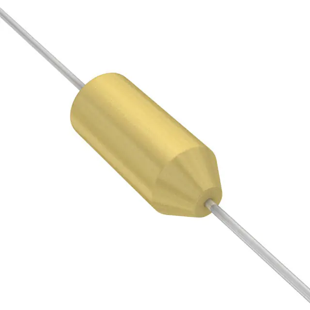
Solid-Electrolyte TANTALEX™ Capacitors,
Axial-Leaded, Molded Case
FEATURES
• Axial through-hole terminations: tin / lead
(SnPb), 100 % tin (RoHS-compliant)
• Miniature axial-lead capacitors available in
Available
5 sizes
• Precision molded in gold colored, flame
Available
retardant, thermosetting epoxy resin
• Laser marked for improved legibility and
tapered end of case provides easy identification of
positive terminal
• Standard orders are lead taped and reeled; orders under
500 are taped only
• Material categorization: for definitions of compliance
please see www.vishay.com/doc?99912
Note
* This datasheet provides information about parts that are
RoHS-compliant and / or parts that are non RoHS-compliant. For
example, parts with lead (Pb) terminations are not RoHS-compliant.
Please see the information / tables in this datasheet for details
LINKS TO ADDITIONAL RESOURCES
3D 3D
APPLICATIONS
3D Models
Designed for high performance automotive, industrial and
commercial electronic equipment.
PERFORMANCE CHARACTERISTICS
Operating Temperature: -55 °C to +85 °C
(to +125 °C with voltage derating)
Capacitance Tolerance: at 120 Hz, +25 °C.
± 20 %, ± 10 % standard ± 5 % available as special
Capacitance Range: 0.10 μF to 330 μF.
Voltage Rating: 2 VDC to 50 VDC.
Dissipation Factor: at 120 Hz, +25 °C. Dissipation factor,
as determined from the expression 2πfRC, shall not exceed
the values listed in the Standard Ratings table.
DC Leakage Current (DCL Max.):
at +25 °C: leakage current shall not exceed the values listed
in the Standard Ratings table.
at +85 °C: leakage current shall not exceed 10 times the
values listed in the Standard Ratings table.
at +125 °C: leakage shall not exceed 15 times the values
listed in the Standard Ratings table.
Life Test: capacitors shall withstand rated DC voltage
applied at +85 °C for 2000 h and for 1000 h applied
at + 25 °C derated voltage.
Following the life test:
1. DCL shall not exceed 125 % of the initial requirements.
2. Dissipation factor shall meet the initial requirement.
3. Change in capacitance shall not exceed ± 10 %.
ORDERING INFORMATION
173D
MODEL
335
CAPACITANCE
X9
CAPACITANCE
TOLERANCE
006
DC VOLTAGE RATING
AT +85 °C
U
CASE
CODE
W
PACKAGING
E3
RoHSCOMPLIANT
This is expressed in picofarads.
The first two digits are the
significant figures. The third is
the number of zeros to follow.
X0 = ± 20 %
X9 = ± 10 %
*X5 = ± 5 %
* Special order
This is expressed in volts.
To complete the three-digit
block, zeros precede the
voltage rating.
See
Ratings
and Case
Codes
table
W = tape
and reel
Blank = ammo
pack
E3 = 100 %
tin termination
(RoHScompliant)
Blank = SnPb
termination
DIMENSIONS in inches [millimeters]
0.875 [22.23]
Min.
(-)
L
Max.
Tinned solid leads
CASE CODE
U
V
W
X
Y
Revision: 08-Feb-2023
D (MAX.)
0.095 [2.41]
0.110 [2.79]
0.180 [4.57]
0.180 [4.57]
0.280 [7.11]
0.875 [22.23]
Min.
(+)
Tapered end identifies anode
L (MAX.)
0.260 [6.60]
0.290 [7.37]
0.345 [8.76]
0.420 [10.67]
0.550 [13.97]
D
Max.
LEAD DIAMETER
0.020 [0.51]
0.020 [0.51]
0.020 [0.51]
0.020 [0.51]
0.025 [0.64]
Document Number: 40019
1
For technical questions, contact: tantalum@vishay.com
THIS DOCUMENT IS SUBJECT TO CHANGE WITHOUT NOTICE. THE PRODUCTS DESCRIBED HEREIN AND THIS DOCUMENT
ARE SUBJECT TO SPECIFIC DISCLAIMERS, SET FORTH AT www.vishay.com/doc?91000
�173D
www.vishay.com
Vishay Sprague
RATINGS AND CASE CODES
μF
2V
4V
6V
10 V
15 V
20 V
25 V
35 V
50 V
0.10
U
U
0.12
U
U
0.15
U
U
0.18
U
U
0.22
U
U
0.27
U
U
0.33
U
V
0.39
U
V
0.47
U
U
V
0.56
U
V
V
0.68
U
V
V
0.82
1.0
U
1.2
U
V
V
U
U
V
V
U
V
V
W
1.5
U
U
V
V
W
1.8
U
V
V
W
W
2.2
U
U
U/V
V
W
W
2.7
U
V
V
V
W
X
3.3
U
U
V
V
V
W
X
3.9
U
V
V
V
W
W
X
4.7
U
U
V
V
V
W
W
X
5.6
U
V
V
V
W
W
X
Y
6.8
U
U
V
V
V
W
W
X
Y
8.2
U
V
V
V
W
W
W
X
Y
10
U
V
V
V
W
W
W
X
Y
12
V
V
V
W
W
X
X
Y
Y
15
V
V
V
W
W
X
X
Y
Y
18
V
V
W
W
X
X
Y
Y
Y
22
V
V
W
W
X
X
Y
Y
Y
27
V
W
W
X
X
Y
Y
Y
33
V
W
W
X
X
Y
Y
Y
39
W
W
X
X
Y
Y
Y
Y
47
W
W
X
X
Y
Y
Y
Y
56
W
X
X
Y
Y
Y
68
W
X
X
Y
Y
Y
82
Y
Y
Y
Y
100
Y
Y
Y
Y
120
Y
Y
Y
150
Y
Y
Y
180
Y
Y
220
Y
Y
270
Y
330
Y
Revision: 08-Feb-2023
Document Number: 40019
2
For technical questions, contact: tantalum@vishay.com
THIS DOCUMENT IS SUBJECT TO CHANGE WITHOUT NOTICE. THE PRODUCTS DESCRIBED HEREIN AND THIS DOCUMENT
ARE SUBJECT TO SPECIFIC DISCLAIMERS, SET FORTH AT www.vishay.com/doc?91000
�173D
www.vishay.com
Vishay Sprague
MARKING
PARAMETER
EXAMPLE
Product type
173D
Polarity
+
Capacitance code, pF
156
Capacitance tolerance code
K
Voltage
25 V
Date code
1209
Lead (Pb)-free indicator (1)
L
Vishay marking
2
Note
(1) On big case sizes (W,X,Y) lead free indicator is printed after date code, for example 1209L.
STANDARD RATINGS
CAPACITANCE
(μF)
CASE CODE
PART NUMBER
MAX. DCL
AT +25 °C
(μA)
MAX. DF
AT +25 °C
120 Hz (%)
2 VDC AT +85 °C, SURGE = 2.5 V; 1.5 VDC AT +125 °C, SURGE = 1.8 V
6.8
U
173D685(1)002U(2)(3)
0.5
8.2
U
173D825(1)002U(2)(3)
0.5
10
10
10
U
173D106(1)002U(2)(3)
0.5
10
12
V
173D126(1)002V(2)(3)
0.5
10
15
V
173D156(1)002V(2)(3)
0.5
10
18
V
173D186(1)002V(2)(3)
0.5
10
22
V
173D226(1)002V(2)(3)
0.5
10
27
V
173D276(1)002V(2)(3)
0.5
10
33
V
173D336(1)002V(2)(3)
0.5
10
39
W
173D396(1)002W(2)(3)
0.6
10
47
W
173D476(1)002W(2)(3)
0.8
10
56
W
173D566(1)002W(2)(3)
0.9
10
68
W
173D686(1)002W(2)(3)
1.1
10
4 VDC AT +85 °C, SURGE = 5 V; 2.5 VDC AT +125 °C, SURGE = 3 V
4.7
U
173D475(1)004U(2)(3)
0.5
8
5.6
U
173D565(1)004U(2)(3)
0.5
8
6.8
U
173D685(1)004U(2)(3)
0.5
8
8.2
V
173D825(1)004V(2)(3)
0.5
8
10
V
173D106(1)004V(2)(3)
0.5
8
12
V
173D126(1)004V(2)(3)
0.5
8
15
V
173D156(1)004V(2)(3)
0.5
8
18
V
173D186(1)004V(2)(3)
0.6
8
22
V
173D226(1)004V(2)(3)
0.7
8
27
W
173D276(1)004W(2)(3)
0.9
8
33
W
173D336(1)004W(2)(3)
1.1
8
39
W
173D396(1)004W(2)(3)
1.2
8
47
W
173D476(1)004W(2)(3)
1.5
8
56
X
173D566(1)004X(2)(3)
1.5
8
68
X
173D686(1)004X(2)(3)
2.2
8
Note
• Part number definition:
(1) For 10 % tolerance specify “X9”; for 20 % specify “X0”; for 5 % specify “X5” (special order)
(2) Packaging code: for reel 13" specify W, leave blank for ammo pack
(3) Termination: for 100 % tin specify E3, for SnPb leave blank
Revision: 08-Feb-2023
Document Number: 40019
3
For technical questions, contact: tantalum@vishay.com
THIS DOCUMENT IS SUBJECT TO CHANGE WITHOUT NOTICE. THE PRODUCTS DESCRIBED HEREIN AND THIS DOCUMENT
ARE SUBJECT TO SPECIFIC DISCLAIMERS, SET FORTH AT www.vishay.com/doc?91000
�173D
www.vishay.com
Vishay Sprague
STANDARD RATINGS
CAPACITANCE
(μF)
3.3
3.9
4.7
5.6
6.8
8.2
10
12
15
18
22
27
33
39
47
56
68
82
100
120
150
180
220
270
330
2.2
2.7
3.3
3.9
4.7
5.6
6.8
8.2
10
12
15
18
22
27
33
39
47
56
68
82
100
CASE CODE
PART NUMBER
MAX. DCL
AT +25 °C
(μA)
6 VDC AT +85 °C, SURGE = 8 V; 4 VDC AT +125 °C, SURGE = 5 V
U
173D335(1)006U(2)(3)
0.5
U
173D395(1)006U(2)(3)
0.5
U
173D475(1)006U(2)(3)
0.5
V
173D565(1)006V(2)(3)
0.5
V
173D685(1)006V(2)(3)
0.5
V
173D825(1)006V(2)(3)
0.5
V
173D106(1)006V(2)(3)
0.5
V
173D126(1)006V(2)(3)
0.6
V
173D156(1)006V(2)(3)
0.7
W
173D186(1)006W(2)(3)
0.9
W
173D226(1)006W(2)(3)
1.1
W
173D276(1)006W(2)(3)
1.3
W
173D336(1)006W(2)(3)
1.5
X
173D396(1)006X(2)(3)
1.6
X
173D476(1)006X(2)(3)
2.3
X
173D566(1)006X(2)(3)
2.7
X
173D686(1)006X(2)(3)
3.3
Y
173D826(1)006Y(2)(3)
3.9
Y
173D107(1)006Y(2)(3)
4.8
Y
173D127(1)006Y(2)(3)
5.0
Y
173D157(1)006Y(2)(3)
5.0
Y
173D187(1)006Y(2)(3)
8.6
Y
173D227(1)006Y(2)(3)
10.0
Y
173D277(1)006Y(2)(3)
10.0
Y
173D337(1)006Y(2)(3)
10.0
10 VDC AT +85 °C, SURGE = 13 V; 7 VDC AT +125 °C, SURGE = 9 V
U
U
U
V
V
V
V
V
V
W
W
W
W
X
X
X
X
Y
Y
Y
Y
173D225(1)010U(2)(3)
173D275(1)010U(2)(3)
173D335(1)010U(2)(3)
173D395(1)010V(2)(3)
173D475(1)010V(2)(3)
173D565(1)010V(2)(3)
173D685(1)010V(2)(3)
173D825(1)010V(2)(3)
173D106(1)010V(2)(3)
173D126(1)010W(2)(3)
173D156(1)010W(2)(3)
173D186(1)010W(2)(3)
173D226(1)010W(2)(3)
173D276(1)010X(2)(3)
173D336(1)010X(2)(3)
173D396(1)010X(2)(3)
173D476(1)010X(2)(3)
173D566(1)010Y(2)(3)
173D686(1)010Y(2)(3)
173D826(1)010Y(2)(3)
173D107(1)010Y(2)(3)
0.5
0.5
0.5
0.5
0.5
0.5
0.5
0.7
0.8
1.0
1.2
1.4
1.5
2.2
2.6
3.1
3.8
4.4
5.0
5.0
8.0
MAX. DF
AT +25 °C
120 Hz (%)
4
4
4
4
6
6
6
6
6
6
6
6
6
6
6
6
6
8
8
8
8
8
8
8
8
4
4
4
4
4
4
6
6
6
6
6
6
6
6
6
6
6
6
6
8
8
Note
• Part number definition:
(1) For 10 % tolerance specify “X9”; for 20 % specify “X0”; for 5 % specify “X5” (special order)
(2) Packaging code: for reel 13" specify W, leave blank for ammo pack
(3) Termination: for 100 % tin specify E3, for SnPb leave blank
Revision: 08-Feb-2023
Document Number: 40019
4
For technical questions, contact: tantalum@vishay.com
THIS DOCUMENT IS SUBJECT TO CHANGE WITHOUT NOTICE. THE PRODUCTS DESCRIBED HEREIN AND THIS DOCUMENT
ARE SUBJECT TO SPECIFIC DISCLAIMERS, SET FORTH AT www.vishay.com/doc?91000
�173D
www.vishay.com
Vishay Sprague
STANDARD RATINGS
CAPACITANCE
(μF)
CASE CODE
PART NUMBER
MAX. DCL
AT +25 °C
(μA)
MAX. DF
AT +25 °C
120 Hz (%)
10 VDC AT +85 °C, SURGE = 13 V; 7 VDC AT +125 °C, SURGE = 9 V
120
150
180
220
Y
173D127(1)010Y(2)(3)
9.6
Y
173D157(1)010Y(2)(3)
10.0
Y
173D187(1)010Y(2)(3)
10.0
Y
173D227(1)010Y(2)(3)
10.0
15 VDC AT +85 °C, SURGE = 20 V; 10 VDC AT +125 °C, SURGE = 12 V
8
8
8
8
1.0
U
173D105(1)015U(2)(3)
0.5
4
1.5
U
173D155(1)015U(2)(3)
0.5
4
1.8
U
173D185(1)015U(2)(3)
0.5
4
2.2
U
173D225(1)015U(2)(3)
0.5
4
2.7
V
173D275(1)015V(2)(3)
0.5
4
3.3
V
173D335(1)015V(2)(3)
0.5
4
3.9
V
173D395(1)015V(2)(3)
0.5
4
4.7
V
173D475(1)015V(2)(3)
0.6
4
5.6
V
173D565(1)015V(2)(3)
0.7
4
6.8
V
173D685(1)015V(2)(3)
0.8
6
8.2
W
173D825(1)015W(2)(3)
1.0
6
10
W
173D106(1)015W(2)(3)
1.2
6
12
W
173D126(1)015W(2)(3)
1.4
6
15
W
173D156(1)015W(2)(3)
1.5
6
18
X
173D186(1)015X(2)(3)
2.2
6
22
X
173D226(1)015X(2)(3)
2.6
6
27
X
173D276(1)015X(2)(3)
3.2
6
33
X
173D336(1)015X(2)(3)
4.0
6
39
Y
173D396(1)015Y(2)(3)
4.7
6
47
Y
173D476(1)015Y(2)(3)
5.0
6
56
Y
173D566(1)015Y(2)(3)
6.7
6
68
Y
173D686(1)015Y(2)(3)
8.2
6
82
Y
173D826(1)015Y(2)(3)
9.8
8
100
Y
173D107(1)015Y(2)(3)
10.0
8
120
Y
173D127(1)015Y(2)(3)
10.0
8
150
Y
173D157(1)015Y(2)(3)
10.0
8
20 VDC AT +85 °C, SURGE = 26 V; 13 VDC AT +125 °C, SURGE = 16 V
1.0
U
173D105(1)020U(2)(3)
0.5
4
1.2
U
173D125(1)020U(2)(3)
0.5
4
1.5
U
173D155(1)020U(2)(3)
0.5
4
1.8
V
173D185(1)020V(2)(3)
0.5
4
2.2
U
173D225(1)020U(2)(3)
0.5
4
2.2
V
173D225(1)020V(2)(3)
0.5
4
2.7
V
173D275(1)020V(2)(3)
0.5
4
3.3
V
173D335(1)020V(2)(3)
0.5
4
3.9
V
173D395(1)020V(2)(3)
0.6
4
4.7
V
173D475(1)020V(2)(3)
0.8
4
5.6
W
173D565(1)020W(2)(3)
0.9
4
Note
• Part number definition:
(1) For 10 % tolerance specify “X9”; for 20 % specify “X0”; for 5 % specify “X5” (special order)
(2) Packaging code: for reel 13" specify W, leave blank for ammo pack
(3) Termination: for 100 % tin specify E3, for SnPb leave blank
Revision: 08-Feb-2023
Document Number: 40019
5
For technical questions, contact: tantalum@vishay.com
THIS DOCUMENT IS SUBJECT TO CHANGE WITHOUT NOTICE. THE PRODUCTS DESCRIBED HEREIN AND THIS DOCUMENT
ARE SUBJECT TO SPECIFIC DISCLAIMERS, SET FORTH AT www.vishay.com/doc?91000
�173D
www.vishay.com
Vishay Sprague
20 VDC AT +85 °C, SURGE = 26 V; 13 VDC AT +125 °C, SURGE = 16 V
6.8
W
173D685(1)020W(2)(3)
1.1
6
8.2
W
173D825(1)020W(2)(3)
1.3
6
10
W
173D106(1)020W(2)(3)
1.6
6
12
X
173D126(1)020X(2)(3)
1.9
6
Revision: 08-Feb-2023
Document Number: 40019
6
For technical questions, contact: tantalum@vishay.com
THIS DOCUMENT IS SUBJECT TO CHANGE WITHOUT NOTICE. THE PRODUCTS DESCRIBED HEREIN AND THIS DOCUMENT
ARE SUBJECT TO SPECIFIC DISCLAIMERS, SET FORTH AT www.vishay.com/doc?91000
�