173D
www.vishay.com
Vishay Sprague
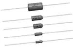
Solid-Electrolyte TANTALEX™ Capacitors,
Axial-Leaded, Molded Case
FEATURES
• Axial through-hole terminations: tin / lead
(SnPb), 100 % tin (RoHS-compliant)
• Miniature axial-lead capacitors available in
Available
5 sizes
• Precision molded in gold colored, flame
Available
retardant, thermosetting epoxy resin
• Laser marked for improved legibility and
tapered end of case provides easy identification of
positive terminal
• Standard orders are lead taped and reeled; orders under
500 are taped only
• Material categorization: for definitions of compliance
please see www.vishay.com/doc?99912
Note
* This datasheet provides information about parts that are
RoHS-compliant and / or parts that are non RoHS-compliant. For
example, parts with lead (Pb) terminations are not RoHS-compliant.
Please see the information / tables in this datasheet for details
LINKS TO ADDITIONAL RESOURCES
3D 3D
APPLICATIONS
3D Models
Designed for high performance automotive, industrial and
commercial electronic equipment.
PERFORMANCE CHARACTERISTICS
Operating Temperature: -55 °C to +85 °C
(to +125 °C with voltage derating)
Capacitance Tolerance: at 120 Hz, +25 °C.
± 20 %, ± 10 % standard ± 5 % available as special
Capacitance Range: 0.10 μF to 330 μF.
Voltage Rating: 2 VDC to 50 VDC.
Dissipation Factor: at 120 Hz, +25 °C. Dissipation factor,
as determined from the expression 2fRC, shall not exceed
the values listed in the Standard Ratings table.
DC Leakage Current (DCL Max.):
at +25 °C: leakage current shall not exceed the values listed
in the Standard Ratings table.
at +85 °C: leakage current shall not exceed 10 times the
values listed in the Standard Ratings table.
at +125 °C: leakage shall not exceed 15 times the values
listed in the Standard Ratings table.
Life Test: capacitors shall withstand rated DC voltage
applied at +85 °C for 2000 h and for 1000 h applied
at + 25 °C derated voltage.
Following the life test:
1. DCL shall not exceed 125 % of the initial requirements.
2. Dissipation factor shall meet the initial requirement.
3. Change in capacitance shall not exceed ± 10 %.
ORDERING INFORMATION
173D
MODEL
335
CAPACITANCE
X9
CAPACITANCE
TOLERANCE
006
DC VOLTAGE RATING
AT +85 °C
U
CASE
CODE
W
PACKAGING
E3
RoHSCOMPLIANT
This is expressed in picofarads.
The first two digits are the
significant figures. The third is
the number of zeros to follow.
X0 = ± 20 %
X9 = ± 10 %
*X5 = ± 5 %
* Special order
This is expressed in volts.
To complete the three-digit
block, zeros precede the
voltage rating.
See
Ratings
and Case
Codes
table
W = tape
and reel
Blank = ammo
pack
E3 = 100 %
tin termination
(RoHScompliant)
Blank = SnPb
termination
DIMENSIONS in inches [millimeters]
0.875 [22.23]
Min.
(-)
L
Max.
Tinned solid leads
CASE CODE
U
V
W
X
Y
Revision: 04-Aug-2020
D (MAX.)
0.095 [2.41]
0.110 [2.79]
0.180 [4.57]
0.180 [4.57]
0.280 [7.11]
0.875 [22.23]
Min.
(+)
Tapered end identifies anode
L (MAX.)
0.260 [6.60]
0.290 [7.37]
0.345 [8.76]
0.420 [10.67]
0.550 [13.97]
D
Max.
LEAD DIAMETER
0.020 [0.51]
0.020 [0.51]
0.020 [0.51]
0.020 [0.51]
0.025 [0.64]
Document Number: 40019
1
For technical questions, contact: tantalum@vishay.com
THIS DOCUMENT IS SUBJECT TO CHANGE WITHOUT NOTICE. THE PRODUCTS DESCRIBED HEREIN AND THIS DOCUMENT
ARE SUBJECT TO SPECIFIC DISCLAIMERS, SET FORTH AT www.vishay.com/doc?91000
�173D
www.vishay.com
Vishay Sprague
RATINGS AND CASE CODES
μF
2V
4V
6V
10 V
15 V
20 V
25 V
35 V
50 V
0.10
U
U
0.12
U
U
0.15
U
U
0.18
U
U
0.22
U
U
0.27
U
U
0.33
U
V
0.39
U
V
0.47
U
U
V
0.56
U
V
V
0.68
U
V
V
0.82
1.0
U
1.2
U
V
V
U
U
V
V
U
V
V
W
1.5
U
U
V
V
W
1.8
U
V
V
W
W
2.2
U
U
U/V
V
W
W
2.7
U
V
V
V
W
X
3.3
U
U
V
V
V
W
X
3.9
U
V
V
V
W
W
X
4.7
U
U
V
V
V
W
W
X
5.6
U
V
V
V
W
W
X
Y
6.8
U
U
V
V
V
W
W
X
Y
8.2
U
V
V
V
W
W
W
X
Y
10
U
V
V
V
W
W
W
X
Y
12
V
V
V
W
W
X
X
Y
Y
15
V
V
V
W
W
X
X
Y
Y
18
V
V
W
W
X
X
Y
Y
Y
22
V
V
W
W
X
X
Y
Y
Y
27
V
W
W
X
X
Y
Y
Y
33
V
W
W
X
X
Y
Y
Y
39
W
W
X
X
Y
Y
Y
Y
47
W
W
X
X
Y
Y
Y
Y
56
W
X
X
Y
Y
Y
68
W
X
X
Y
Y
Y
82
Y
Y
Y
Y
100
Y
Y
Y
Y
120
Y
Y
Y
150
Y
Y
Y
180
Y
Y
220
Y
Y
270
Y
330
Y
Revision: 04-Aug-2020
Document Number: 40019
2
For technical questions, contact: tantalum@vishay.com
THIS DOCUMENT IS SUBJECT TO CHANGE WITHOUT NOTICE. THE PRODUCTS DESCRIBED HEREIN AND THIS DOCUMENT
ARE SUBJECT TO SPECIFIC DISCLAIMERS, SET FORTH AT www.vishay.com/doc?91000
�173D
www.vishay.com
Vishay Sprague
MARKING
PARAMETER
EXAMPLE
Product type
173D
Polarity
+
Capacitance code, pF
156
Capacitance tolerance code
K
Voltage
25 V
Date code
1209
Lead (Pb)-free indicator (1)
L
Vishay marking
2
Note
(1) On big case sizes (W,X,Y) lead free indicator is printed after date code, for example 1209L.
STANDARD RATINGS
CAPACITANCE
(μF)
CASE CODE
PART NUMBER
MAX. DCL
AT +25 °C
(μA)
MAX. DF
AT +25 °C
120 Hz (%)
2 VDC AT +85 °C, SURGE = 2.5 V; 1.5 VDC AT +125 °C, SURGE = 1.8 V
6.8
U
173D685(1)002U(2)(3)
0.5
8.2
U
173D825(1)002U(2)(3)
0.5
10
10
10
U
173D106(1)002U(2)(3)
0.5
10
12
V
173D126(1)002V(2)(3)
0.5
10
15
V
173D156(1)002V(2)(3)
0.5
10
18
V
173D186(1)002V(2)(3)
0.5
10
22
V
173D226(1)002V(2)(3)
0.5
10
27
V
173D276(1)002V(2)(3)
0.5
10
33
V
173D336(1)002V(2)(3)
0.5
10
39
W
173D396(1)002W(2)(3)
0.6
10
47
W
173D476(1)002W(2)(3)
0.8
10
56
W
173D566(1)002W(2)(3)
0.9
10
68
W
173D686(1)002W(2)(3)
1.1
10
4 VDC AT +85 °C, SURGE = 5 V; 2.5 VDC AT +125 °C, SURGE = 3 V
4.7
U
173D475(1)004U(2)(3)
0.5
8
5.6
U
173D565(1)004U(2)(3)
0.5
8
6.8
U
173D685(1)004U(2)(3)
0.5
8
8.2
V
173D825(1)004V(2)(3)
0.5
8
10
V
173D106(1)004V(2)(3)
0.5
8
12
V
173D126(1)004V(2)(3)
0.5
8
15
V
173D156(1)004V(2)(3)
0.5
8
18
V
173D186(1)004V(2)(3)
0.6
8
22
V
173D226(1)004V(2)(3)
0.7
8
27
W
173D276(1)004W(2)(3)
0.9
8
33
W
173D336(1)004W(2)(3)
1.1
8
39
W
173D396(1)004W(2)(3)
1.2
8
47
W
173D476(1)004W(2)(3)
1.5
8
56
X
173D566(1)004X(2)(3)
1.5
8
68
X
173D686(1)004X(2)(3)
2.2
8
Note
• Part number definition:
(1) For 10 % tolerance specify “X9”; for 20 % specify “X0”; for 5 % specify “X5” (special order)
(2) Packaging code: for reel 13" specify W, leave blank for ammo pack
(3) Termination: for 100 % tin specify E3, for SnPb leave blank
Revision: 04-Aug-2020
Document Number: 40019
3
For technical questions, contact: tantalum@vishay.com
THIS DOCUMENT IS SUBJECT TO CHANGE WITHOUT NOTICE. THE PRODUCTS DESCRIBED HEREIN AND THIS DOCUMENT
ARE SUBJECT TO SPECIFIC DISCLAIMERS, SET FORTH AT www.vishay.com/doc?91000
�173D
www.vishay.com
Vishay Sprague
STANDARD RATINGS
CAPACITANCE
(μF)
3.3
3.9
4.7
5.6
6.8
8.2
10
12
15
18
22
27
33
39
47
56
68
82
100
120
150
180
220
270
330
2.2
2.7
3.3
3.9
4.7
5.6
6.8
8.2
10
12
15
18
22
27
33
39
47
56
68
82
100
CASE CODE
PART NUMBER
MAX. DCL
AT +25 °C
(μA)
6 VDC AT +85 °C, SURGE = 8 V; 4 VDC AT +125 °C, SURGE = 5 V
U
173D335(1)006U(2)(3)
0.5
U
173D395(1)006U(2)(3)
0.5
U
173D475(1)006U(2)(3)
0.5
V
173D565(1)006V(2)(3)
0.5
V
173D685(1)006V(2)(3)
0.5
V
173D825(1)006V(2)(3)
0.5
V
173D106(1)006V(2)(3)
0.5
V
173D126(1)006V(2)(3)
0.6
V
173D156(1)006V(2)(3)
0.7
W
173D186(1)006W(2)(3)
0.9
W
173D226(1)006W(2)(3)
1.1
W
173D276(1)006W(2)(3)
1.3
W
173D336(1)006W(2)(3)
1.5
X
173D396(1)006X(2)(3)
1.6
X
173D476(1)006X(2)(3)
2.3
X
173D566(1)006X(2)(3)
2.7
X
173D686(1)006X(2)(3)
3.3
Y
173D826(1)006Y(2)(3)
3.9
Y
173D107(1)006Y(2)(3)
4.8
Y
173D127(1)006Y(2)(3)
5.0
Y
173D157(1)006Y(2)(3)
5.0
Y
173D187(1)006Y(2)(3)
8.6
Y
173D227(1)006Y(2)(3)
10.0
Y
173D277(1)006Y(2)(3)
10.0
Y
173D337(1)006Y(2)(3)
10.0
10 VDC AT +85 °C, SURGE = 13 V; 7 VDC AT +125 °C, SURGE = 9 V
U
U
U
V
V
V
V
V
V
W
W
W
W
X
X
X
X
Y
Y
Y
Y
173D225(1)010U(2)(3)
173D275(1)010U(2)(3)
173D335(1)010U(2)(3)
173D395(1)010V(2)(3)
173D475(1)010V(2)(3)
173D565(1)010V(2)(3)
173D685(1)010V(2)(3)
173D825(1)010V(2)(3)
173D106(1)010V(2)(3)
173D126(1)010W(2)(3)
173D156(1)010W(2)(3)
173D186(1)010W(2)(3)
173D226(1)010W(2)(3)
173D276(1)010X(2)(3)
173D336(1)010X(2)(3)
173D396(1)010X(2)(3)
173D476(1)010X(2)(3)
173D566(1)010Y(2)(3)
173D686(1)010Y(2)(3)
173D826(1)010Y(2)(3)
173D107(1)010Y(2)(3)
0.5
0.5
0.5
0.5
0.5
0.5
0.5
0.7
0.8
1.0
1.2
1.4
1.5
2.2
2.6
3.1
3.8
4.4
5.0
5.0
8.0
MAX. DF
AT +25 °C
120 Hz (%)
4
4
4
4
6
6
6
6
6
6
6
6
6
6
6
6
6
8
8
8
8
8
8
8
8
4
4
4
4
4
4
6
6
6
6
6
6
6
6
6
6
6
6
6
8
8
Note
• Part number definition:
(1) For 10 % tolerance specify “X9”; for 20 % specify “X0”; for 5 % specify “X5” (special order)
(2) Packaging code: for reel 13" specify W, leave blank for ammo pack
(3) Termination: for 100 % tin specify E3, for SnPb leave blank
Revision: 04-Aug-2020
Document Number: 40019
4
For technical questions, contact: tantalum@vishay.com
THIS DOCUMENT IS SUBJECT TO CHANGE WITHOUT NOTICE. THE PRODUCTS DESCRIBED HEREIN AND THIS DOCUMENT
ARE SUBJECT TO SPECIFIC DISCLAIMERS, SET FORTH AT www.vishay.com/doc?91000
�173D
www.vishay.com
Vishay Sprague
STANDARD RATINGS
CAPACITANCE
(μF)
CASE CODE
PART NUMBER
MAX. DCL
AT +25 °C
(μA)
MAX. DF
AT +25 °C
120 Hz (%)
10 VDC AT +85 °C, SURGE = 13 V; 7 VDC AT +125 °C, SURGE = 9 V
120
150
180
220
Y
173D127(1)010Y(2)(3)
9.6
Y
173D157(1)010Y(2)(3)
10.0
Y
173D187(1)010Y(2)(3)
10.0
Y
173D227(1)010Y(2)(3)
10.0
15 VDC AT +85 °C, SURGE = 20 V; 10 VDC AT +125 °C, SURGE = 12 V
8
8
8
8
1.0
U
173D105(1)015U(2)(3)
0.5
4
1.5
U
173D155(1)015U(2)(3)
0.5
4
1.8
U
173D185(1)015U(2)(3)
0.5
4
2.2
U
173D225(1)015U(2)(3)
0.5
4
2.7
V
173D275(1)015V(2)(3)
0.5
4
3.3
V
173D335(1)015V(2)(3)
0.5
4
3.9
V
173D395(1)015V(2)(3)
0.5
4
4.7
V
173D475(1)015V(2)(3)
0.6
4
5.6
V
173D565(1)015V(2)(3)
0.7
4
6.8
V
173D685(1)015V(2)(3)
0.8
6
8.2
W
173D825(1)015W(2)(3)
1.0
6
10
W
173D106(1)015W(2)(3)
1.2
6
12
W
173D126(1)015W(2)(3)
1.4
6
15
W
173D156(1)015W(2)(3)
1.5
6
18
X
173D186(1)015X(2)(3)
2.2
6
22
X
173D226(1)015X(2)(3)
2.6
6
27
X
173D276(1)015X(2)(3)
3.2
6
33
X
173D336(1)015X(2)(3)
4.0
6
39
Y
173D396(1)015Y(2)(3)
4.7
6
47
Y
173D476(1)015Y(2)(3)
5.0
6
56
Y
173D566(1)015Y(2)(3)
6.7
6
68
Y
173D686(1)015Y(2)(3)
8.2
6
82
Y
173D826(1)015Y(2)(3)
9.8
8
100
Y
173D107(1)015Y(2)(3)
10.0
8
120
Y
173D127(1)015Y(2)(3)
10.0
8
150
Y
173D157(1)015Y(2)(3)
10.0
8
20 VDC AT +85 °C, SURGE = 26 V; 13 VDC AT +125 °C, SURGE = 16 V
1.0
U
173D105(1)020U(2)(3)
0.5
4
1.2
U
173D125(1)020U(2)(3)
0.5
4
1.5
U
173D155(1)020U(2)(3)
0.5
4
1.8
V
173D185(1)020V(2)(3)
0.5
4
2.2
U
173D225(1)020U(2)(3)
0.5
4
2.2
V
173D225(1)020V(2)(3)
0.5
4
2.7
V
173D275(1)020V(2)(3)
0.5
4
3.3
V
173D335(1)020V(2)(3)
0.5
4
3.9
V
173D395(1)020V(2)(3)
0.6
4
4.7
V
173D475(1)020V(2)(3)
0.8
4
5.6
W
173D565(1)020W(2)(3)
0.9
4
Note
• Part number definition:
(1) For 10 % tolerance specify “X9”; for 20 % specify “X0”; for 5 % specify “X5” (special order)
(2) Packaging code: for reel 13" specify W, leave blank for ammo pack
(3) Termination: for 100 % tin specify E3, for SnPb leave blank
Revision: 04-Aug-2020
Document Number: 40019
5
For technical questions, contact: tantalum@vishay.com
THIS DOCUMENT IS SUBJECT TO CHANGE WITHOUT NOTICE. THE PRODUCTS DESCRIBED HEREIN AND THIS DOCUMENT
ARE SUBJECT TO SPECIFIC DISCLAIMERS, SET FORTH AT www.vishay.com/doc?91000
�173D
www.vishay.com
Vishay Sprague
STANDARD RATINGS
CAPACITANCE
(μF)
CASE CODE
PART NUMBER
MAX. DCL
AT +25 °C
(μA)
MAX. DF
AT +25 °C
120 Hz (%)
20 VDC AT +85 °C, SURGE = 26 V; 13 VDC AT +125 °C, SURGE = 16 V
6.8
W
173D685(1)020W(2)(3)
1.1
6
8.2
W
173D825(1)020W(2)(3)
1.3
6
10
W
173D106(1)020W(2)(3)
1.6
6
12
X
173D126(1)020X(2)(3)
1.9
6
15
X
173D156(1)020X(2)(3)
2.4
6
18
X
173D186(1)020X(2)(3)
2.9
6
22
X
173D226(1)020X(2)(3)
3.5
6
27
Y
173D276(1)020Y(2)(3)
4.3
6
33
Y
173D336(1)020Y(2)(3)
5.0
6
39
Y
173D396(1)020Y(2)(3)
6.2
6
47
Y
173D476(1)020Y(2)(3)
7.5
6
56
Y
173D566(1)020Y(2)(3)
8.9
6
68
Y
173D686(1)020Y(2)(3)
10.0
6
82
Y
173D826(1)020Y(2)(3)
10.0
6
100
Y
173D107(1)020Y(2)(3)
10.0
6
25 VDC AT +85 °C, SURGE = 32 V; 17 VDC AT +125 °C, SURGE = 21 V
0.47
U
173D474(1)025U(2)(3)
0.5
3
0.56
U
173D564(1)025U(2)(3)
0.5
3
0.68
U
173D684(1)025U(2)(3)
0.5
3
0.82
U
173D824(1)025U(2)(3)
0.5
3
1.0
U
173D105(1)025U(2)(3)
0.5
3
1.2
V
173D125(1)025V(2)(3)
0.5
3
1.5
V
173D155(1)025V(2)(3)
0.5
3
1.8
V
173D185(1)025V(2)(3)
0.5
3
2.2
V
173D225(1)025V(2)(3)
0.5
3
2.7
V
173D275(1)025V(2)(3)
0.5
3
3.3
V
173D335(1)025V(2)(3)
0.7
3
3.9
W
173D395(1)025W(2)(3)
0.8
3
4.7
W
173D475(1)025W(2)(3)
0.9
4
5.6
W
173D565(1)025W(2)(3)
1.1
4
6.8
W
173D685(1)025W(2)(3)
1.4
4
8.2
W
173D825(1)025W(2)(3)
1.5
4
10
W
173D106(1)025W(2)(3)
1.5
4
12
X
173D126(1)025X(2)(3)
2.4
4
15
X
173D156(1)025X(2)(3)
3.0
4
18
Y
173D186(1)025Y(2)(3)
3.6
6
22
Y
173D226(1)025Y(2)(3)
4.4
6
27
Y
173D276(1)025Y(2)(3)
5.4
6
33
Y
173D336(1)025Y(2)(3)
6.6
6
39
Y
173D396(1)025Y(2)(3)
7.8
6
47
Y
173D476(1)025Y(2)(3)
9.4
6
Note
• Part number definition:
(1) For 10 % tolerance specify “X9”; for 20 % specify “X0”; for 5 % specify “X5” (special order)
(2) Packaging code: for reel 13" specify W, leave blank for ammo pack
(3) Termination: for 100 % tin specify E3, for SnPb leave blank
Revision: 04-Aug-2020
Document Number: 40019
6
For technical questions, contact: tantalum@vishay.com
THIS DOCUMENT IS SUBJECT TO CHANGE WITHOUT NOTICE. THE PRODUCTS DESCRIBED HEREIN AND THIS DOCUMENT
ARE SUBJECT TO SPECIFIC DISCLAIMERS, SET FORTH AT www.vishay.com/doc?91000
�173D
www.vishay.com
Vishay Sprague
STANDARD RATINGS
CAPACITANCE
(μF)
CASE CODE
PART NUMBER
MAX. DCL
AT +25 °C
(μA)
MAX. DF
AT +25 °C
120 Hz (%)
35 VDC AT +85 °C, SURGE = 46 V; 23 VDC AT +125 °C, SURGE = 28 V
0.10
U
173D104(1)035U(2)(3)
0.5
3
0.12
U
173D124(1)035U(2)(3)
0.5
3
0.15
U
173D154(1)035U(2)(3)
0.5
3
0.18
U
173D184(1)035U(2)(3)
0.5
3
0.22
U
173D224(1)035U(2)(3)
0.5
3
0.27
U
173D274(1)035U(2)(3)
0.5
3
0.33
U
173D334(1)035U(2)(3)
0.5
3
0.39
U
173D394(1)035U(2)(3)
0.5
3
0.47
U
173D474(1)035U(2)(3)
0.5
3
0.56
V
173D564(1)035V(2)(3)
0.5
3
0.68
V
173D684(1)035V(2)(3)
0.5
3
0.82
V
173D824(1)035V(2)(3)
0.5
3
1.0
V
173D105(1)035V(2)(3)
0.5
3
1.2
V
173D125(1)035V(2)(3)
0.5
3
1.5
V
173D155(1)035V(2)(3)
0.5
3
1.8
W
173D185(1)035W(2)(3)
0.5
3
2.2
W
173D225(1)035W(2)(3)
0.6
3
2.7
W
173D275(1)035W(2)(3)
0.8
3
3.3
W
173D335(1)035W(2)(3)
0.9
4
3.9
W
173D395(1)035W(2)(3)
1.1
4
4.7
W
173D475(1)035W(2)(3)
1.3
4
5.6
X
173D565(1)035X(2)(3)
1.6
4
6.8
X
173D685(1)035X(2)(3)
1.9
4
8.2
X
173D825(1)035X(2)(3)
2.3
4
10
X
173D106(1)035X(2)(3)
2.8
4
12
Y
173D126(1)035Y(2)(3)
3.3
4
15
Y
173D156(1)035Y(2)(3)
4.2
4
18
Y
173D186(1)035Y(2)(3)
5.0
6
22
Y
173D226(1)035Y(2)(3)
6.2
6
27
Y
173D276(1)035Y(2)(3)
7.5
6
33
Y
173D336(1)035Y(2)(3)
9.2
6
39
Y
173D396(1)035Y(2)(3)
10.0
6
Y
173D476(1)035Y(2)(3)
10.0
6
47
50 VDC AT +85 °C, SURGE = 65 V; 33 VDC AT +125 °C, SURGE = 40 V
0.10
U
173D104(1)050U(2)(3)
0.5
3
0.12
U
173D124(1)050U(2)(3)
0.5
3
0.15
U
173D154(1)050U(2)(3)
0.5
3
0.18
U
173D184(1)050U(2)(3)
0.5
3
0.22
U
173D224(1)050U(2)(3)
0.5
3
0.27
U
173D274(1)050U(2)(3)
0.5
3
0.33
V
173D334(1)050V(2)(3)
0.5
3
0.39
V
173D394(1)050V(2)(3)
0.5
3
Note
• Part number definition:
(1) For 10 % tolerance specify “X9”; for 20 % specify “X0”; for 5 % specify “X5” (special order)
(2) Packaging code: for reel 13" specify W, leave blank for ammo pack
(3) Termination: for 100 % tin specify E3, for SnPb leave blank
Revision: 04-Aug-2020
Document Number: 40019
7
For technical questions, contact: tantalum@vishay.com
THIS DOCUMENT IS SUBJECT TO CHANGE WITHOUT NOTICE. THE PRODUCTS DESCRIBED HEREIN AND THIS DOCUMENT
ARE SUBJECT TO SPECIFIC DISCLAIMERS, SET FORTH AT www.vishay.com/doc?91000
�173D
www.vishay.com
Vishay Sprague
STANDARD RATINGS
CAPACITANCE
(μF)
CASE CODE
MAX. DCL
AT +25 °C
(μA)
PART NUMBER
MAX. DF
AT +25 °C
120 Hz (%)
50 VDC AT +85 °C, SURGE = 65 V; 33 VDC AT +125 °C, SURGE = 40 V
0.47
0.56
0.68
0.82
1.0
1.2
1.5
1.8
2.2
2.7
3.3
3.9
4.7
5.6
6.8
8.2
10
12
15
18
22
V
V
V
V
V
W
W
W
W
X
X
X
X
Y
Y
Y
Y
Y
Y
Y
Y
173D474(1)050V(2)(3)
173D564(1)050V(2)(3)
173D684(1)050V(2)(3)
173D824(1)050V(2)(3)
173D105(1)050V(2)(3)
173D125(1)050W(2)(3)
173D155(1)050W(2)(3)
173D185(1)050W(2)(3)
173D225(1)050W(2)(3)
173D275(1)050X(2)(3)
173D335(1)050X(2)(3)
173D395(1)050X(2)(3)
173D475(1)050X(2)(3)
173D565(1)050Y(2)(3)
173D685(1)050Y(2)(3)
173D825(1)050Y(2)(3)
173D106(1)050Y(2)(3)
173D126(1)050Y(2)(3)
173D156(1)050Y(2)(3)
173D186(1)050Y(2)(3)
173D226(1)050Y(2)(3)
0.5
0.5
0.5
0.5
0.5
0.5
0.6
0.7
0.9
1.1
1.3
1.6
1.9
2.2
2.7
3.2
4.0
5.0
6.0
6.0
11.0
3
3
3
3
3
3
3
4
4
4
4
4
4
4
4
4
6
6
6
6
6
Note
• Part number definition:
(1) For 10 % tolerance specify “X9”; for 20 % specify “X0”; for 5 % specify “X5” (special order)
(2) Packaging code: for reel 13" specify W, leave blank for ammo pack
(3) Termination: for 100 % tin specify E3, for SnPb leave blank
TAPE AND REEL PACKAGING in inches [millimeters]
13 [330.2] dia.
Standard reel
“A”
Component overall
length (1.b)
C
(1.b)
(1.a)
1.126 to 3.07
[28.6 to 78.0]
I. D. reel HUB
Tape
spacing
B
Component
spacing (4.b)
A
1.374 to 3.626
[34.9 to 92.1]
0.047 [1.19] max.
off center (1.a)
0.625 ± 0.062
[15.88 ± 1.57]
dia. thru hole
0.125 [3.18] max.
“A”
Label (4.a)
0.250 [6.35] (3.b)
0.750 [19.05]
0.031 [0.79] (3.f)
SECTION “A” - ”A”
CASE CODE
UNITS PER REEL
COMPONENT SPACING
A
U
V
W, X
4500
4000
2500
0.200 ± 0.015
[5.08 ± 3.81]
Y
500
0.400 ± 0.015
[10.16 ± 3.81]
Revision: 04-Aug-2020
(Both sides) (3.f)
TAPE SPACING
B
UNITS PER AMMOPACK
1000
2.062 ± 0.062
[52.37 ± 1.57]
500
Document Number: 40019
8
For technical questions, contact: tantalum@vishay.com
THIS DOCUMENT IS SUBJECT TO CHANGE WITHOUT NOTICE. THE PRODUCTS DESCRIBED HEREIN AND THIS DOCUMENT
ARE SUBJECT TO SPECIFIC DISCLAIMERS, SET FORTH AT www.vishay.com/doc?91000
�173D
www.vishay.com
Vishay Sprague
STANDARD REEL PACKAGING INFORMATION
1. Component Leads
a. Component leads shall not be bent beyond 0.047"
[1.19 mm] maximum from their nominal position when
measured from the leading edge of the component lead
at the inside tape edge and at the lead egress from the
component.
b. The “C” dimension shall be governed by the overall
length of the reel packaged component. The distance
between flanges shall be 0.125" to 0.250" [3.18 mm to
6.35 mm] greater than the overall component length.
2. Orientation
All polarized components must be oriented to one direction.
The cathode lead tape shall be a color and the anode lead
tape shall be white.
3. Reeling
a. Components on any reel shall not represent more than
two date codes when date code identification is required.
b. Component leads shall be positioned between pairs of
0.250" [6.35 mm] tape.
c. The disposable reels have hubs and corrugated
fibreboard flanges and core.
d. A minimum of 12" [304.8 mm] leader of tape shall be
provided before the first and after the last component on
the reel.
e. 50 lb to 60 lb. Kraft paper must be wound between layers
of components as far as necessary for component
protection. Width of paper to be 0.062" to 0.250"
[1.57 mm to 6.35 mm] less than the “C” dimension
of the reel.
f. Row components must be centered between tapes
± 0.047" [1.19 mm]. In addition, individual components
may deviate from center of component row ± 0.031"
[0.79 mm].
g. Staples shall not be used for splicing. Not more than
4 layers of tape shall be used in any splice area and no
tape shall be offset from another by more than 0.031"
[0.79 mm] non-cumulative. Tape splices shall overlap
at least 6.0" [152.4 mm] for butt joints and at least
3" [76.2 mm] for lap joints and shall not be weaker than
unspliced tape. Universal splicing clips may also be used.
h. Quantity per reel shall be controlled so that tape
components and cover shall not extend beyond the
smallest dimension of the flange (either across flats or
diameter). Once the quantity per reel for each part
number has been established, future orders for that part
number shall be packaged in that quantity. When order
release quantity is less than the established quantity, a
standard commercial pack is to be used.
i. A maximum of 0.25 % of the components per reel
quantity may be missing without consecutive missing
components.
j. Adequate protection must be provided to prevent
physical damage to both reel and components during
shipment and storage
PRODUCT INFORMATION
Mounting of Through Hole Components
www.vishay.com/doc?40108
Solid Tantalum Capacitors (With MnO2 Electrolyte) Voltage Derating
www.vishay.com/doc?40246
SELECTOR GUIDES
Quick Reference Guide
www.vishay.com/doc?40037
Selector Guide
www.vishay.com/doc?49054
Parameter Comparison Guide
www.vishay.com/doc?40033
FAQ
Frequently Asked Questions
Revision: 04-Aug-2020
www.vishay.com/doc?40110
Document Number: 40019
9
For technical questions, contact: tantalum@vishay.com
THIS DOCUMENT IS SUBJECT TO CHANGE WITHOUT NOTICE. THE PRODUCTS DESCRIBED HEREIN AND THIS DOCUMENT
ARE SUBJECT TO SPECIFIC DISCLAIMERS, SET FORTH AT www.vishay.com/doc?91000
�Legal Disclaimer Notice
www.vishay.com
Vishay
Disclaimer
ALL PRODUCT, PRODUCT SPECIFICATIONS AND DATA ARE SUBJECT TO CHANGE WITHOUT NOTICE TO IMPROVE
RELIABILITY, FUNCTION OR DESIGN OR OTHERWISE.
Vishay Intertechnology, Inc., its affiliates, agents, and employees, and all persons acting on its or their behalf (collectively,
“Vishay”), disclaim any and all liability for any errors, inaccuracies or incompleteness contained in any datasheet or in any other
disclosure relating to any product.
Vishay makes no warranty, representation or guarantee regarding the suitability of the products for any particular purpose or
the continuing production of any product. To the maximum extent permitted by applicable law, Vishay disclaims (i) any and all
liability arising out of the application or use of any product, (ii) any and all liability, including without limitation special,
consequential or incidental damages, and (iii) any and all implied warranties, including warranties of fitness for particular
purpose, non-infringement and merchantability.
Statements regarding the suitability of products for certain types of applications are based on Vishay's knowledge of typical
requirements that are often placed on Vishay products in generic applications. Such statements are not binding statements
about the suitability of products for a particular application. It is the customer's responsibility to validate that a particular product
with the properties described in the product specification is suitable for use in a particular application. Parameters provided in
datasheets and / or specifications may vary in different applications and performance may vary over time. All operating
parameters, including typical parameters, must be validated for each customer application by the customer's technical experts.
Product specifications do not expand or otherwise modify Vishay's terms and conditions of purchase, including but not limited
to the warranty expressed therein.
Hyperlinks included in this datasheet may direct users to third-party websites. These links are provided as a convenience and
for informational purposes only. Inclusion of these hyperlinks does not constitute an endorsement or an approval by Vishay of
any of the products, services or opinions of the corporation, organization or individual associated with the third-party website.
Vishay disclaims any and all liability and bears no responsibility for the accuracy, legality or content of the third-party website
or for that of subsequent links.
Except as expressly indicated in writing, Vishay products are not designed for use in medical, life-saving, or life-sustaining
applications or for any other application in which the failure of the Vishay product could result in personal injury or death.
Customers using or selling Vishay products not expressly indicated for use in such applications do so at their own risk. Please
contact authorized Vishay personnel to obtain written terms and conditions regarding products designed for such applications.
No license, express or implied, by estoppel or otherwise, to any intellectual property rights is granted by this document or by
any conduct of Vishay. Product names and markings noted herein may be trademarks of their respective owners.
© 2022 VISHAY INTERTECHNOLOGY, INC. ALL RIGHTS RESERVED
Revision: 01-Jan-2022
1
Document Number: 91000
�


 工商网监
湘ICP备2023018690号
工商网监
湘ICP备2023018690号
