199D
www.vishay.com
Vishay Sprague
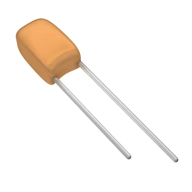
Solid-Electrolyte TANTALEX™ Capacitors,
Resin-Coated, Radial-Lead
FEATURES
• Terminations: tin / lead (SnPb), 100 % tin (Sn)
• Economy and high performance are combined
Available
in
these
radial-lead,
solid-electrolyte
TANTALEX™ capacitors
• Rugged, reliable capacitors featuring low Available
leakage current and low dissipation factor
• Six miniature case sizes and five lead styles. All case sizes
are available in standard tape and reel packaging per
EIA-468
• Standard ratings include replacements for type 196D
capacitors
• Lead (Pb)-free capacitors have “L” in body marking
• Material categorization: for definitions of compliance
please see www.vishay.com/doc?99912
Note
* This datasheet provides information about parts that are
RoHS-compliant and / or parts that are non RoHS-compliant. For
example, parts with lead (Pb) terminations are not RoHS-compliant.
Please see the information / tables in this datasheet for details
APPLICATIONS
Suitable for a broad range of consumer, commercial and
industrial equipment
PERFORMANCE CHARACTERISTICS
Operating Temperature: -55 °C to +85 °C
(to +125 °C with voltage derating)
Capacitance Tolerance: at 120 Hz, +25 °C, ± 20 %,
± 10 % standard. ± 5 % available as special
Dissipation Factor: at 120 Hz, +25 °C. Dissipation factor,
shall not exceed the values listed in the Standard Ratings
tables.
DC Leakage Current (DCL Max.):
at +25 °C: leakage current shall not exceed the values listed
in the Standard Ratings tables.
at +85 °C: leakage current shall not exceed 10 times the
values listed in the Standard Ratings tables.
at +125 °C: leakage shall not exceed 15 times the values
listed in the Standard Ratings tables.
Life Test: capacitors shall withstand rated DC voltage
applied at +85 °C for 1000 h with a circuit resistance not
greater than 3 Ω.
Following the life test:
1. DCL shall not exceed 125 % of the initial requirements
2. Dissipation factor shall meet the initial requirement
3. Change in capacitance shall not exceed ± 10 %
ORDERING INFORMATION
199D
475
X9
003
A
1 (1)
V1
E3
MODEL
CAPACITANCE
CAPACITANCE
TOLERANCE
DC VOLTAGE RATING
AT +85 °C
CASE
CODE
LEAD
STYLE
PACKAGING
RoHSCOMPLIANT
This is expressed in
picofarads. The first
two digits are the
significant figures.
The third is the
number of zeros to
follow.
X0 = ± 20 %
X9 = ± 10 %
** X5 = ± 5 %
** Special Order
This is expressed in V.
To complete the
three-digit block, zeros
precede the voltage
rating. A decimal point
is indicated by an “R”
(6R3 = 6.3 V).
See
Ratings
and
Case
Codes
table.
V1 = bulk
B1 = tape and reel
A1 = tape /
ammo box
E3 = 100 %
tin termination
(RoHS-compliant)
Blank = tin / lead
termination
Note
(1) See lead styles table
Revision: 08-Feb-2023
Document Number: 40020
1
For technical questions, contact: tantalum@vishay.com
THIS DOCUMENT IS SUBJECT TO CHANGE WITHOUT NOTICE. THE PRODUCTS DESCRIBED HEREIN AND THIS DOCUMENT
ARE SUBJECT TO SPECIFIC DISCLAIMERS, SET FORTH AT www.vishay.com/doc?91000
�199D
www.vishay.com
Vishay Sprague
LEAD STYLE CONFIGURATIONS AND CODES
STRAIGHT UNEVEN LEADS
CODES 1, 3, AND Y
STRAIGHT EVEN LEADS
CODES 2, 4, AND 5
D
D
+
+
3±1
H
“OUTSIDE HOCKEY STICK”
CODES 6 AND 7
+
+
H1
1.1 ± 0.05
L
P
P
6.35 max.
D
+
+
L
L
“HAIRPIN”
CODES X, Z
D
D
+
+
H
“SNAP-IN”
CODE 9
H
H
L
P
H1
L
P
P
Notes
• Wire diameter (nominal) 0.020" (0.51 mm)
• L = lead length
• P = pitch or lead spacing
AVAILABLE LEAD STYLES AND PACKAGING TYPES PER CASE SIZE
LEAD STYLE / CASE
1
2
3
4
5
6
Bulk
Bulk
Reel
Ammo
-
-
Bulk
Reel
Ammo
-
Bulk
7
9
X
Y
Z
Bulk
Reel
Ammo
Bulk
Reel
Ammo
Bulk
Reel
Ammo
Bulk
Bulk
Reel
Ammo
-
-
-
-
-
A
B
C
D
E
F
Bulk / Reel
Ammo
Bulk
Reel
Ammo
-
DIMENSIONS FOR LEAD STYLES 1, 2, 3, 4, 5, Y, 6 in inches [millimeters]
LEAD STYLE
1, 2, 3, 4
1, 3
2, 4
5, Y
6
CASE
D
(max.)
P (1)
± 0.024
[0.60]
H
(max.)
L (2)
(min.)
L (2)
± 0.118
[3.0]
P (1)
± 0.03
[0.76]
L (2)
± 0.118
[3.0]
P (1)
± 0.024
[0.60]
H1
(max.)
L (2)
A
0.173
[4.40]
0.100
[2.54]
0.280
[7.11]
0.591
[15.0]
0.748
[19.0]
0.125
[3.18]
0.748
[19.0]
0.200
[5.08]
0.378
[9.61]
0.240 ± 0.030
[6.1 ± 0.76]
B
0.197
[5.00]
0.100
[2.54]
0.300
[7.62]
0.591
[15.0]
0.748
[19.0]
0.125
[3.18]
0.748
[19.0]
0.200
[5.08]
0.398
[10.11]
0.240 ± 0.030
[6.1 ± 0.76]
C
0.217
[5.50]
0.100
[2.54]
0.360
[9.14]
0.591
[15.0]
0.748
[19.0]
0.125
[3.18]
0.748
[19.0]
0.200
[5.08]
0.458
[11.64]
0.240 ± 0.030
[6.1 ± 0.76]
D
0.236
[6.00]
0.100
[2.54]
0.400
[10.16]
0.591
[15.0]
0.748
[19.0]
0.125
[3.18]
0.748
[19.0]
0.200
[5.08]
0.498
[12.66]
0.240 ± 0.030
[6.1 ± 0.76]
E
0.339
[8.60]
0.200
[5.08]
0.492
[12.50]
0.591
[15.0]
0.748
[19.0]
n/a
n/a
0.200
[5.08]
0.591
[15.00]
1.0 ± 0.122
[25.4 ± 3.1]
F
0.378
[9.60]
0.200
[5.08]
0.650
[16.50]
0.591
[15.0]
0.748
[19.0]
n/a
n/a
0.200
[5.08]
0.748
[19.00]
1.0 ± 0.122
[25.4 ± 3.1]
Notes
(1) Pitch or lead spacing P measured within 0.05" [1.27 mm] of the body of the capacitor or from the bottom of the crimp
(2) Lead length L is for bulk packaging
Revision: 08-Feb-2023
Document Number: 40020
2
For technical questions, contact: tantalum@vishay.com
THIS DOCUMENT IS SUBJECT TO CHANGE WITHOUT NOTICE. THE PRODUCTS DESCRIBED HEREIN AND THIS DOCUMENT
ARE SUBJECT TO SPECIFIC DISCLAIMERS, SET FORTH AT www.vishay.com/doc?91000
�199D
www.vishay.com
Vishay Sprague
DIMENSIONS FOR LEAD STYLES 7, 9, X, Z in inches [millimeters]
LEAD STYLE
7
9
H1
max.
L (2)
± 0.03
[0.76]
P (1)
± 0.024
[0.60]
X, Z
H1
max.
L (2)
± 0.03
[0.76]
D
max.
H
max.
X
Z
H1
max.
L (2)
± 0.125
[3.175]
P (1)
± 0.024
[0.60]
P (1)
± 0.024
[0.60]
CASE
D
max.
P (1)
± 0.024
[0.60]
A
0.173
[4.40]
0.25
[6.35]
0.378
[9.61]
0.240 ± 0.030
[6.1 ± 0.76]
0.200
[5.08]
0.398
[10.11]
0.240
[6.10]
0.173
[4.40]
0.280
[7.11]
0.340
[8.64]
0.750
[19.05]
0.100
[2.54]
0.125
[3.175]
B
0.197
[5.00]
0.25
[6.35]
0.398 0.240 ± 0.030
[10.12]
[6.1 ± 0.76]
0.200
[5.08]
0.418
[10.62]
0.240
[6.10]
0.197
[5.00]
0.300
[7.62]
0.360
[9.14]
0.750
[19.05]
0.100
[2.54]
0.125
[3.175]
C
0.217
[5.50]
0.25
[6.35]
0.458 0.240 ± 0.030
[11.64]
[6.1 ± 0.76]
0.200
[5.08]
0.478
[12.14]
0.240
[6.10]
0.217
[5.50]
0.360
[9.14]
0.420
[10.67]
0.750
[19.05]
0.100
[2.54]
0.125
[3.175]
D
0.236
[6.00]
0.25
[6.35]
0.498 0.240 ± 0.030
[12.66]
[6.1 ± 0.76]
0.200
[5.08]
0.518
[13.16]
0.240
[6.10]
0.236
[6.00]
0.400
[10.16]
0.460
[11.68]
0.750
[19.05]
0.100
[2.54]
0.125
[3.175]
Notes
(1) Pitch or lead spacing P measured within 0.05" [1.27 mm] of the body of the capacitor or from the bottom of the crimp
(2) Lead length L is for bulk packaging
199D OBSOLETE VS. CURRENT ORDERING CROSS REFERENCE
OBSOLETE
NEW
DESCRIPTION
A1
1V1
PITCH 0.100, UNEVEN STRAIGHT LEADS, BULK CASES A - D
A1
3V1
PITCH 0.200, UNEVEN STRAIGHT LEADS, BULK, CASES E, F
A1
2V1
PITCH 0.100, EVEN STRAIGHT LEADS, BULK, CASES A - D
A6
2B1
PITCH 0.100, EVEN STRAIGHT LEADS, REEL POSITIVE LEADER, CASES A - D
A6
2A1
PITCH 0.100, EVEN STRAIGHT LEADS, AMMO, CASES A - D
A1
4V1
PITCH 0.200, EVEN STRAIGHT LEADS, BULK, CASES E, F
A6
4B1
PITCH 0.200, EVEN STRAIGHT LEADS, REEL POSITIVE LEADER, CASES E, F
A6
4A1
PITCH 0.200, EVEN STRAIGHT LEADS, AMMO, CASES E, F
A2
5V1
PITCH 0.125, EVEN STRAIGHT LEADS, BULK, CASES A - D
A7
5B1
PITCH 0.125, EVEN STRAIGHT LEADS, REEL POSITIVE LEADER, CASES A - D
A7
5A1
PITCH 0.125, EVEN STRAIGHT LEADS, AMMO, CASES A - D
PITCH 0.125, UNEVEN STRAIGHT LEADS, BULK, CASES A - D
A2
YV1
B1
XV1
PITCH 0.100, HAIRPIN LEADS, BULK CASES A - D
B6
XB1
PITCH 0.100, HAIRPIN LEADS, REEL POSITIVE LEADER, CASES A - D
B6
XA1
PITCH 0.100, HAIRPIN LEADS, AMMO, CASES A - D
B2
ZV1
PITCH 0.125, HAIRPIN LEADS, BULK, CASES A - D
B7
ZB1
PITCH 0.125, HAIRPIN LEADS, REEL POSITIVE LEADER, CASES A - D
B7
ZA1
PITCH 0.125, HAIRPIN LEADS, AMMO, CASES A - D
E2
6V1
PITCH 0.200, HOCKEY STICK LEADS, BULK, CASES A - F
E7
6B1
PITCH 0.200, HOCKEY STICK LEADS, REEL POSITIVE LEADER, CASES A - F
E7
6A1
PITCH 0.200, HOCKEY STICK LEADS, AMMO, CASES A - F
E3
7V1
PITCH 0.250, HOCKEY STICK LEADS, BULK, CASES A - D
E8
7B1
PITCH 0.250, HOCKEY STICK LEADS, REEL POSITIVE LEADER, CASES A - D
E8
7A1
PITCH 0.250, HOCKEY STICK LEADS, AMMO, CASES A - D
G2
9V1
PITCH 0.200, SNAP-IN LEADS, BULK, CASES A - D
G7
9B1
PITCH 0.200, SNAP-IN LEADS, REEL POSITIVE LEADER, CASES A - D
G7
9A1
PITCH 0.200, SNAP-IN LEADS, AMMO, CASES A - D
E4
Revision: 08-Feb-2023
OBSOLETE
Document Number: 40020
3
For technical questions, contact: tantalum@vishay.com
THIS DOCUMENT IS SUBJECT TO CHANGE WITHOUT NOTICE. THE PRODUCTS DESCRIBED HEREIN AND THIS DOCUMENT
ARE SUBJECT TO SPECIFIC DISCLAIMERS, SET FORTH AT www.vishay.com/doc?91000
�199D
www.vishay.com
Vishay Sprague
STANDARD RATINGS
CAPACITANCE
(μF)
CASE CODE
PART NUMBER
MAX. DCL
AT +25 °C
(μA)
MAX. DF
AT +25 °C
120 Hz (%)
3 VDC AT +85 °C, SURGE = 3.6 V; 2 VDC AT +125 °C, SURGE = 2.4 V
4.7
A
199D475(1)003A(2)(3)
0.5
6
6.8
A
199D685(1)003A(2)(3)
0.5
6
10
A
199D106(1)003A(2)(3)
0.5
8
15
A
199D156(1)003A(2)(3)
0.5
8
22
B
199D226(1)003B(2)(3)
0.6
8
33
B
199D336(1)003B(2)(3)
1.0
8
47
C
199D476(1)003C(2)(3)
1.4
8
68
C
199D686(1)003C(2)(3)
2.0
8
100
D
199D107(1)003D(2)(3)
3.0
10
150
D
199D157(1)003D(2)(3)
4.0
10
220
E
199D227(1)003E(2)(3)
5.0
10
330
E
199D337(1)003E(2)(3)
6.0
10
470
F
199D477(1)003F(2)(3)
8.0
10
680
F
199D687(1)003F(2)(3)
10.0
10
6.3 VDC AT +85 °C, SURGE = 8 V; 4 VDC AT +125 °C, SURGE = 5 V
4.7
A
199D475(1)6R3A(2)(3)
0.5
6
6.8
A
199D685(1)6R3A(2)(3)
0.5
6
10
B
199D106(1)6R3B(2)(3)
0.6
8
15
B
199D156(1)6R3B(2)(3)
0.9
8
22
C
199D226(1)6R3C(2)(3)
1.3
8
33
C
199D336(1)6R3C(2)(3)
2.0
8
47
D
199D476(1)6R3D(2)(3)
2.9
8
68
D
199D686(1)6R3D(2)(3)
4.0
8
100
D
199D107(1)6R3D(2)(3)
5.0
10
150
E
199D157(1)6R3E(2)(3)
6.0
10
220
E
199D227(1)6R3E(2)(3)
7.0
10
330
F
199D337(1)6R3F(2)(3)
8.0
10
10 VDC AT +85 °C, SURGE = 13 V; 7 VDC AT +125 °C, SURGE = 9 V
3.3
A
199D335(1)010A(2)(3)
0.5
6
4.7
A
199D475(1)010A(2)(3)
0.5
6
6.8
B
199D685(1)010B(2)(3)
0.6
6
10
B
199D106(1)010B(2)(3)
1.0
8
15
C
199D156(1)010C(2)(3)
1.5
8
22
C
199D226(1)010C(2)(3)
2.0
8
33
D
199D336(1)010D(2)(3)
3.0
8
39
D
199D396(1)010D(2)(3)
3.9
8
47
D
199D476(1)010D(2)(3)
4.0
8
68
D
199D686(1)010D(2)(3)
5.0
8
100
E
199D107(1)010E(2)(3)
6.0
10
150
E
199D157(1)010E(2)(3)
7.0
10
220
F
199D227(1)010F(2)(3)
8.0
10
Note
• Part number definitions:
(1) For capacitance tolerance: X0 = ± 20 %, X9 = ± 10 % or X5 = 5 %
(2) To specify lead style / spacing / packaging insert the last three characters in the part number. Use the appropriate code shown in the
Current Ordering Cross Reference table and explained in the Ordering Information and Lead Styles table
(3) E3 = RoHS-compliant 100 % tin leads. Blank or no suffix = standard tin / lead termination
Revision: 08-Feb-2023
Document Number: 40020
4
For technical questions, contact: tantalum@vishay.com
THIS DOCUMENT IS SUBJECT TO CHANGE WITHOUT NOTICE. THE PRODUCTS DESCRIBED HEREIN AND THIS DOCUMENT
ARE SUBJECT TO SPECIFIC DISCLAIMERS, SET FORTH AT www.vishay.com/doc?91000
�


 工商网监
湘ICP备2023018690号
工商网监
湘ICP备2023018690号
