Bulletin PD-2.080 rev. C 11/02
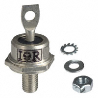
1N6392
60 Amp
SCHOTTKY RECTIFIER
TO-203AB (DO-5)
Description/ Features
Major Ratings and Characteristics
The 1N6392 Schottky rectifier has been optimized for low
reverse leakage at high temperature. The proprietary barrier
technology allows for reliable operation up to 175° C junction
temperature. Typical applications are in switching power
supplies, converters, free-wheeling diodes, and reverse battery protection.
Characteristics
1N6392
Units
IF(AV) Rectangular
60*
A
45*
V
IFSM @ 60Hz
1000*
A
Low forward voltage drop
VF
@ 60 Apk, TJ = 25 °C
0.68*
V
High frequency operation
Guard ring for enhanced ruggedness and long term
reliability
TJ
range
- 55 to 175*
°C
Hermetic packaging
waveform
VRWM
175° C TJ operation
Military qualified versions also available
* JEDEC Registered Values
Conforms to JEDEC Outline DO-203AB (DO-5)
Dimensions in millimeters and (inches)
www.irf.com
1
�1N6392
Bulletin PD-2.080 rev. C 11/02
Voltage Ratings
Part number
VR
1N6392
Max. DC Reverse Voltage (V)
45*
VRWM Max. Working Peak Reverse Voltage (V)
Absolute Maximum Ratings
Parameters
1N6392 Units
IF(AV) Max. Average Forward Current
60*
See Fig. 5
IFSM
54*
Max. Peak One Cycle Non-Repetitive
Surge Current
See Fig. 7
9000
A
A
1000*
Conditions
50% duty cycle @ TC = 115 °C, rectangular wave form
50% duty cycle @ TC = 115 °C, sinusoidal wave form
5µs Sine or 3µs Rect. pulse. Following any rated load
condition and with rated VRRM applied
60Hz half cycle sine wave or 5ms rectangular pulse
EAS
Non-Repetitive Avalanche Energy
101
mJ
IAR
Repetitive Avalanche Current
15
A
TJ = 25 °C, IAS = 15 Amps, L = 0.9 mH
Current decaying linearly to zero in 1 µsec
Frequency limited by TJ max. VA = 1.5 x VR typical
Electrical Specifications
Parameters
VFM
IRM
1N6392 Units
Max. Forward Voltage Drop
See Fig. 1
(1)
Max. Reverse Leakage Current (1)
See Fig. 2
0.47*
0.68*
0.82*
0.59*
V
V
V
V
20*
mA
Conditions
@ 10A
@ 60A
@ 120A
@ 10A
TJ = 25 °C
TJ = - 55 °C
TJ = 25 °C
60*
mA
TJ = 125 °C
600*
mA
TJ = 175°C
VR = rated VR
CT
Max. Junction Capacitance
3000
pF
VR = 5VDC, (test signal range 100Khz to 1Mhz) 25 °C
LS
Typical Series Inductance
7.5
nH
Measured from top of terminal to mounting plane
dv/dt Max. Voltage Rate of Change
10000
V/ µs (Rated VR)
(1) Pulse Width < 300µs, Duty Cycle < 2%
Thermal-Mechanical Specifications
Parameters
1N6392 Units
TJ
Max. Junction Temperature Range
-55 to 175*
Tstg
Max. Storage Temperature Range
-55 to 175*
RthJC Max. Thermal Resistance Junction
to Case
RthCS Typical Thermal Resistance, Case to
Heatsink
RthCA Max. Thermal Resistance, Case to
Ambient
wt
Approximate Weight
T
Mounting Torque
Case Style
Conditions
°C
°C
1.0*
°C/W DC operation
See Fig. 4
0.25*
°C/W Mounting surface, smooth and greased
7.0*
°C/W RthCA is the value for which device blocking stability with
rated VR or VRWM applied assured, when TA = 25°C and
TC = 148°C (DC) or TC = 163°C (AC operation)
15.6(0.55) g (oz.)
Min.
Max.
2.26 (20) N-m Non-lubricated threads
3.39 (30) (Ibf-in)
DO-203AB(DO-5) JEDEC
* JEDEC Registered Values
2
www.irf.com
�1N6392
Bulletin PD-2.080 rev. C 11/02
1000
1000
T =175°C
J
ReverseCurrent - I (mA)
R
100
150°C
10
125°C
1
100°C
75°C
.1
50°C
.01
25°C
.001
0
5
10 15 20 25 30 35 40 45
ReverseVoltage- VR(V)
T =175°C
J
Fig. 2 - Typical Values of Reverse Current
Vs. Reverse Voltage
T = 25°C
J
10000
JunctionCapacitance- C (pF)
T
InstantaneousForwardCurrent - IF (A)
100
10
1
0
.2
.4
.6
.8
1
1.2
T =25°C
J
1000
100
0
1.4
10
20
30
40
50
ReverseVoltage- V (V)
R
ForwardVoltageDrop- V (V)
FM
Fig. 1 - Maximum Forward Voltage Drop Characteristics
Fig. 3 - Typical Junction Capacitance
Vs. Reverse Voltage
Thermal Impedance- ZthJC (°C/W
)
10
1
.1
D=0.50
D=0.33
D=0.25
D=0.17
D=0.08
P
DM
t
1
t2
Notes:
1. Dutyfactor D= t1/ t 2
.01
SinglePulse
(Thermal Resistance)
.001
.00001
.0001
.001
2. PeakT
J=P
DMxZthJC+TC
.01
.1
1
10
100
t1, Rectangular PulseDuration(Seconds)
Fig. 4 - Maximum Thermal Impedance ZthJC Characteristics
www.irf.com
3
�1N6392
Bulletin PD-2.080 rev. C 11/02
170
50
1N6392
RthJC (DC) =1.0°C/W
AveragePower Loss - (W
atts)
AllowableCaseTemperature- (°C)
180
160
150
DC
140
130
120
0
40
D=0.08
D=0.17
D=0.25
D=0.33
D=0.50
30
20 RMSLimit
10
0
0
10 20 30 40 50 60 70 80 90
DC
10 20 30 40 50 60 70 80 90
AverageForwardCurrent - I
(A)
F(AV)
AverageForwardCurrent - IF(AV) (A)
Fig. 5 - Maximum Allowable Case Temperature
Vs. Average Forward Current
Fig. 6 - Forward Power Loss Characteristics
Non-RepetitiveSurgeCurrent - I
(A)
FSM
10000
At Any RatedLoadCondition
AndW
ithRatedV
Applied
RRM
FollowingSurge
1000
10
100
1000
10000
SquareW
avePulseDuration- tp (microsec)
Fig. 7 - Maximum Non-Repetitive Surge Current
L
DUT
IRFP460
Rg = 25 ohm
CURRENT
MONITOR
HIGH-SPEED
SWITCH
FREE-WHEEL
DIODE
+
Vd = 25 Volt
40HFL40S02
Fig. 8 - Unclamped Inductive Test Circuit
4
www.irf.com
�1N6392
Bulletin PD-2.080 rev. C 11/02
Data and specifications subject to change without notice.
This product has been designed for Industrial Level.
Qualification Standards can be found on IR's Web site.
IR WORLD HEADQUARTERS: 233 Kansas St., El Segundo, California 90245, USA Tel: (310) 252-7105
TAC Fax: (310) 252-7309
Visit us at www.irf.com for sales contact information. 11/02
www.irf.com
5
�
很抱歉,暂时无法提供与“1N6392”相匹配的价格&库存,您可以联系我们找货
免费人工找货- 国内价格 香港价格
- 100+39.30566100+5.09477