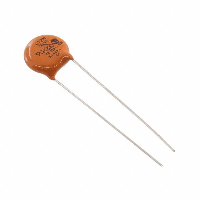
30LVS Series
www.vishay.com
Vishay Cera-Mite
AC Line Rated Disc Capacitors
Class X1, 400 VAC / Class Y2, 300 VAC / 250 VAC
FEATURES
• Complying with IEC 60384-14 3rd edition
• High reliability
• Complete range of capacitance values
• Radial leads
• Singlelayer AC disc safety capacitors
• Material categorization: for definitions of compliance
please see www.vishay.com/doc?99912
APPLICATIONS
• X1 / Y2 according to IEC 60384-14.3
• Across-the-line
QUICK REFERENCE DATA
DESCRIPTION
• Line by-pass
VALUE
Ceramic Class
• Antenna coupling
2
Ceramic Dielectric
Y5U
Y5U
Y5U
Y5V
Y5V
Y5V
Voltage (VAC)
250
300
400
250
300
400
Min. Capacitance (pF)
1000
4700
Max. Capacitance (pF)
10 000
10 000
Mounting
Radial
INSULATION RESISTANCE
DESIGN
The capacitors consist of a ceramic disc of which both sides
are silver-plated. Connection leads are made of tinned
copper having a diameter of 0.032" (0.81 mm) or 0.025"
(0.64 mm). The capacitors may be supplied with radial
kinked or straight leads having a lead spacing of 0.375"
(9.5 mm) or 0.250" (6.4 mm). The standard tolerance is
± 20 %. Coating is made of flame retardant epoxy resin in
accordance with “UL 94 V-0.”
Min. 1000 F
CAPACITANCE RANGE
TOLERANCE ON CAPACITANCE
1.0 nF to 0.01 μF
± 20 %
RATED VOLTAGE
DISSIPATION FACTOR
IEC 60384-14.3:
2.0 % max. at 1 kHz; 1 V
• X1:
400 VAC, 50 Hz
CERAMIC DIELECTRIC
• Y2:
300 VAC, 50 Hz (LS 5.5 mm)
Y5U, Y5V (Class 2)
• Y2:
250 VAC, 50 Hz (LS < 5.5 mm)
CLIMATIC CATEGORY ACC. TO EN 60068-1
DIELECTRIC STRENGTH BETWEEN LEADS
25/125/21
Component test:
2500 VAC, 50 Hz, 2 s
OPERATING TEMPERATURE RANGE
As repeated test admissible only once with:
2250 VAC, 50 Hz, 2 s
-30 °C to +125 °C
Random sampling test (destructive test):
2500 VAC, 50 Hz, 60 s
DIELECTRIC STRENGTH OF BODY INSULATION
2300 VAC, 50 Hz, 60 s (destructive test)
Revision: 03-Mar-15
Document Number: 23104
1
For technical questions, contact: ceramitesupport@vishay.com
THIS DOCUMENT IS SUBJECT TO CHANGE WITHOUT NOTICE. THE PRODUCTS DESCRIBED HEREIN AND THIS DOCUMENT
ARE SUBJECT TO SPECIFIC DISCLAIMERS, SET FORTH AT www.vishay.com/doc?91000
�30LVS Series
www.vishay.com
Vishay Cera-Mite
DIMENSIONS in inches (millimeters)
1.250 min.
(32)
Dmax.
LO
LS
Tinned Copper Leads
Ø
Tmax.
0.125
max. (3.2)
ORDERING INFORMATION, CERAMIC X1 / Y2 CAPACITORS 30LVS
C
(pF)
Y5U
1000
1500
2000
2200
2700
2800
3000
3200
3300
3900
4000
4700
5000
5500
6800
0.010 μF
Y5V
4700
0.010 μF
TOL.
(%)
Dmax.
DIAMETER
INCH (mm)
Tmax.
THICKNESS
INCH (mm)
± 20
0.330 (8.4)
0.330 (8.4)
0.330 (8.4)
0.330 (8.4)
0.365 (9.3)
0.365 (9.3)
0.400 (10.2)
0.400 (10.2)
0.400 (10.2)
0.460 (11.7)
0.490 (12.4)
0.490 (12.4)
0.530 (13.5)
0.530 (13.5)
0.620 (15.7)
0.720 (18.3)
0.195 (5.0)
0.185 (4.7)
0.180 (4.6)
0.170 (4.3)
0.180 (4.6)
0.175 (4.4)
0.180 (4.6)
0.180 (4.6)
0.175 (4.4)
0.185 (4.7)
0.190 (4.8)
0.185 (4.7)
0.190 (4.8)
0.180 (4.6)
0.200 (5.1)
0.200 (5.1)
0.430 (10.9)
0.620 (15.7)
0.185 (4.7)
0.200 (5.1)
± 20
± 20
WIRE SIZE
AWG
INCH (mm)
LS
LEAD SPACE
INCH (mm)
± 1 mm
22
0.025 (0.64)
0.250 (6.4)
20
0.032 (0.81)
0.375 (9.5)
22
20
0.025 (0.64)
0.032 (0.81)
0.250 (6.4)
0.375 (9.5)
LO
LEAD OFFSET
INCH (mm)
± 0.5 mm
ORDERING
CODE
0.098 (2.5)
0.091 (2.3)
0.083 (2.1)
0.079 (2.0)
0.083 (2.1)
0.079 (2.0)
0.083 (2.1)
0.091 (2.3)
0.083 (2.1)
0.098 (2.5)
0.102 (2.6)
0.094 (2.4)
0.098 (2.5)
0.091 (2.3)
0.098 (2.5)
0.102 (2.6)
30LVSD10-R
30LVSD15-R
30LVSD20-R
30LVSD22-R
30LVSD27-R
30LVSD28-R
30LVSD30-R
30LVSD32-R
30LVSD33-R
30LVSD39-R
30LVSD40-R
30LVSD47-R
30LVSD50-R
30LVSD55-R
30LVSD68-R
30LVSS10-R
0.091 (2.3)
0.098 (2.5)
30LVSVD47-R
30LVSVS10-R
Notes
• Alternate lead spacings of 7.5 mm and 10 mm are available bulk or tape and reel on request.
• Minimum lead clearance according to IEC 60384-14: 0.118" (3 mm)
TAPE AND REEL OPTIONS
Part number codes and specifications for tape and reel packaging are found in the general information document - find web-link
below.
OPTIONAL 3-LEADED STYLE
An optional 3-leaded construction is available. It consists of a single capacitor with the two outside leads attached to one
electrode, and the center lead attached to the electrode. Used in feed-thru or line-to-ground applications, it allows a short
ground lead for enhanced high frequency performance.
a
D
max.
4 mm max.
1.250" min. (32)
Revision: 03-Mar-15
a
LS
G
b
G
c
b
T
Document Number: 23104
2
For technical questions, contact: ceramitesupport@vishay.com
THIS DOCUMENT IS SUBJECT TO CHANGE WITHOUT NOTICE. THE PRODUCTS DESCRIBED HEREIN AND THIS DOCUMENT
ARE SUBJECT TO SPECIFIC DISCLAIMERS, SET FORTH AT www.vishay.com/doc?91000
�30LVS Series
www.vishay.com
Vishay Cera-Mite
LEAKAGE CURRENT VS. VOLTAGE (Typical)
INSERTION LOSS VS. FREQUENCY (Typical)
10
30LVSD28-R
30LVSD27-R
1.5
30LVSD22-R
30LVSD20-R
1
30LVSD15-R
30LVSD10-R
0.5
Insertion Loss (dB)
Leakage Current (mA) RMS
2
0
20
30
40
50
30LVSD28-R
30LVSD27-R
30LVSD22-R
100
0
500
1000
1500
2000
2500
1
10
30LVSD40-R
30LVSD39-R
1.5
30LVSD33-R
30LVSD32-R
30LVSD30-R
1
0.5
10
Insertion Loss (dB)
Leakage Current (mA) RMS
2
0
500
1000
1500
AC Voltage (V) RMS
2000
30
40
50
30LVSD40-R
30LVSD39-R
30LVSD33-R
30LVSD30-R
30LVSD32-R
100
10
Frequency (MHz)
30LVSS10-R
10
4
30LVSD68-R
3
30LVSD55-R
30LVSD50-R
30LVSD47-R
2
1
0
Insertion Loss (dB)
Leakage Current (mA) RMS
20
100
1
2500
5
30
40
50
100
0
500
1000
1500
AC Voltage (V) RMS
2000
2500
30LVSD47-R
30LVSD50-R
1
10
100
Frequency (MHz)
30LVSVS10-R
2
30LVSVD47-R
1
Insertion Loss (dB)
10
3
0
20
30LVSS10-R
30LVSD68-R
30LVSD55-R
4
Leakage Current (mA) RMS
100
Frequency (MHz)
AC Voltage (V) RMS
0
30LVSD10-R
30LVSD15-R
30LVSD20-R
20
30
40
50
30LVSVS10-R
30LVSVD47-R
100
0
500
Revision: 03-Mar-15
1000
1500
AC Voltage (V) RMS
2000
1
10
100
Frequency (MHz)
Document Number: 23104
3
For technical questions, contact: ceramitesupport@vishay.com
THIS DOCUMENT IS SUBJECT TO CHANGE WITHOUT NOTICE. THE PRODUCTS DESCRIBED HEREIN AND THIS DOCUMENT
ARE SUBJECT TO SPECIFIC DISCLAIMERS, SET FORTH AT www.vishay.com/doc?91000
�30LVS Series
www.vishay.com
Vishay Cera-Mite
APPROVALS
IEC 60384-14.3 - Safety tests
This approval together with CB test certificate substitutes all national approvals.
CB Certificate
Y2-capacitor: CB test certificate:
CA/14038/CSA
1 nF to 10 nF
300 VAC (1)
Y2-capacitor: CB test certificate:
CA/14038/CSA
1 nF to 10 nF
250 VAC (1)
X1-capacitor: CB test certificate:
CA/14038/CSA
1 nF to 10 nF
400 VAC
VDE
Y2-capacitor: VDE marks approval:
40003969
1 nF to 10 nF
250 VAC
X1-capacitor: VDE marks approval:
40003969
1 nF to 10 nF
400 VAC
Y2-capacitor: UL test certificate:
E99264
1 nF to 10 nF
300 VAC (1)
Y2-capacitor: UL test certificate:
E99264
1 nF to 10 nF
250 VAC (1)
X1-capacitor: UL test certificate:
E99264
1 nF to 10 nF
400 VAC
DIN EN 60384-14 VDE 0565-1-1:2006-04 - Safety tests
Underwriters Laboratories Inc.
UL 60384-14, CSA E60384-1:03, CSA E60384-14:09
Fixed capacitors for electromagnetic interference suppression and connection to the supply mains.
Note
(1) LS 5.5 mm: 300 V ; LS < 5.5 mm: 250 V
AC
AC
MARKING
Sample
103M
30LVS
125 °C
Y2 250 ~
X1 400 ~
CM
RELATED DOCUMENTS
General Information
www.vishay.com/doc?23140
CB Test Certificate
www.vishay.com/doc?22231
VDE Marks Approval
www.vishay.com/doc?22232
UL Test Certificate
www.vishay.com/doc?22233
Revision: 03-Mar-15
Document Number: 23104
4
For technical questions, contact: ceramitesupport@vishay.com
THIS DOCUMENT IS SUBJECT TO CHANGE WITHOUT NOTICE. THE PRODUCTS DESCRIBED HEREIN AND THIS DOCUMENT
ARE SUBJECT TO SPECIFIC DISCLAIMERS, SET FORTH AT www.vishay.com/doc?91000
�Legal Disclaimer Notice
www.vishay.com
Vishay
Disclaimer
ALL PRODUCT, PRODUCT SPECIFICATIONS AND DATA ARE SUBJECT TO CHANGE WITHOUT NOTICE TO IMPROVE
RELIABILITY, FUNCTION OR DESIGN OR OTHERWISE.
Vishay Intertechnology, Inc., its affiliates, agents, and employees, and all persons acting on its or their behalf (collectively,
“Vishay”), disclaim any and all liability for any errors, inaccuracies or incompleteness contained in any datasheet or in any other
disclosure relating to any product.
Vishay makes no warranty, representation or guarantee regarding the suitability of the products for any particular purpose or
the continuing production of any product. To the maximum extent permitted by applicable law, Vishay disclaims (i) any and all
liability arising out of the application or use of any product, (ii) any and all liability, including without limitation special,
consequential or incidental damages, and (iii) any and all implied warranties, including warranties of fitness for particular
purpose, non-infringement and merchantability.
Statements regarding the suitability of products for certain types of applications are based on Vishay’s knowledge of typical
requirements that are often placed on Vishay products in generic applications. Such statements are not binding statements
about the suitability of products for a particular application. It is the customer’s responsibility to validate that a particular
product with the properties described in the product specification is suitable for use in a particular application. Parameters
provided in datasheets and/or specifications may vary in different applications and performance may vary over time. All
operating parameters, including typical parameters, must be validated for each customer application by the customer’s
technical experts. Product specifications do not expand or otherwise modify Vishay’s terms and conditions of purchase,
including but not limited to the warranty expressed therein.
Except as expressly indicated in writing, Vishay products are not designed for use in medical, life-saving, or life-sustaining
applications or for any other application in which the failure of the Vishay product could result in personal injury or death.
Customers using or selling Vishay products not expressly indicated for use in such applications do so at their own risk. Please
contact authorized Vishay personnel to obtain written terms and conditions regarding products designed for such applications.
No license, express or implied, by estoppel or otherwise, to any intellectual property rights is granted by this document or by
any conduct of Vishay. Product names and markings noted herein may be trademarks of their respective owners.
Material Category Policy
Vishay Intertechnology, Inc. hereby certifies that all its products that are identified as RoHS-Compliant fulfill the
definitions and restrictions defined under Directive 2011/65/EU of The European Parliament and of the Council
of June 8, 2011 on the restriction of the use of certain hazardous substances in electrical and electronic equipment
(EEE) - recast, unless otherwise specified as non-compliant.
Please note that some Vishay documentation may still make reference to RoHS Directive 2002/95/EC. We confirm that
all the products identified as being compliant to Directive 2002/95/EC conform to Directive 2011/65/EU.
Vishay Intertechnology, Inc. hereby certifies that all its products that are identified as Halogen-Free follow Halogen-Free
requirements as per JEDEC JS709A standards. Please note that some Vishay documentation may still make reference
to the IEC 61249-2-21 definition. We confirm that all the products identified as being compliant to IEC 61249-2-21
conform to JEDEC JS709A standards.
Revision: 02-Oct-12
1
Document Number: 91000
�


 工商网监
湘ICP备2023018690号
工商网监
湘ICP备2023018690号
