715C..KT...
www.vishay.com
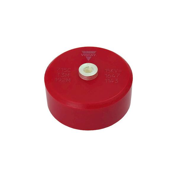
Vishay Cera-Mite
High Voltage Class 1 Ceramic AC and DC Disc Capacitors,
10 kVDC to 50 kVDC / 7 kVAC to 34 kVAC, Screw Terminal Mounting
FEATURES
• Low dissipation factor of 0.2 % at 1 kHz
• N4700 (T3M) class 1, strontium-based ceramic
dielectric
• Negligible piezoelectric / electrostrictive effect
• Low inductance
• High insulation resistance
• Epoxy coating
• Screw terminal mounting
• Ceramic singlelayer capacitor
• Material categorization: for definitions of compliance
please see www.vishay.com/doc?99912
APPLICATIONS
DESIGN SUPPORT TOOLS
click logo to get started
Models
Available
•
•
•
•
•
High voltage power supplies
CO2 lasers
X-ray equipment
Welding equipment
Industrial
QUICK REFERENCE DATA
DESCRIPTION
Ceramic Class
Ceramic Dielectric
Type
Voltage (VDC)
Min. Capacitance (pF)
Max. Capacitance (pF)
Mounting
715C10KT###
10 000
560
8000
715C15KT###
15 000
370
5300
VALUE
1
N4700
715C20KT###
715C30KT###
20 000
30 000
200
190
4000
2700
Screw terminal
DIELECTRIC STRENGTH
RATED VOLTAGE
150 % of rated voltage, charging current limited to 50 mA
•
•
•
•
•
•
DISSIPATION FACTOR tan
2 x 10⁻³ (1 kHz)
INSULATION RESISTANCE
Min. 200 000 M or 1000 F min. at 25 °C
CORONA LIMIT
< 5 pC at 50 % of rated AC voltage
715C40KT###
40 000
100
2000
715C50KT###
50 000
100
1700
(1)
10 kVDC (7 kVRMS)
15 kVDC (10 kVRMS)
20 kVDC (14 kVRMS)
30 kVDC (20 kVRMS)
40 kVDC (27 kVRMS)
50 kVDC (34 kVRMS)
Note
(1)
All kVRMS values up to 60 Hz
MATERIAL
-30 °C to +85 °C
Capacitor elements made from class 1 ceramic in a molded
epoxy case. Screw terminals: brass, silver plated.
CAPACITANCE RANGE
MARKING
100 pF to 8 nF
Type designator, capacitance value, rated DC voltage,
ceramic material code, production date code, Cera-Mite
logo.
OPERATING TEMPERATURE RANGE
CAPACITANCE TOLERANCES
± 20 %
POWER DISSIPATION
CERAMIC DIELECTRIC
Limit to 20 °C rise above ambient, measured on case.
N4700 (class 1)
Revision: 13-Aug-2018
Document Number: 22210
1
For technical questions, contact: powcap@vishay.com
THIS DOCUMENT IS SUBJECT TO CHANGE WITHOUT NOTICE. THE PRODUCTS DESCRIBED HEREIN AND THIS DOCUMENT
ARE SUBJECT TO SPECIFIC DISCLAIMERS, SET FORTH AT www.vishay.com/doc?91000
�715C..KT...
www.vishay.com
Vishay Cera-Mite
DIMENSIONS in millimeters (inches)
H ± 1 (0.04)
D ± 1 (0.04)
8-32NC-2B tapped holes standard terminal (1)
or
M4 / M5 tapped holes (2)
Notes
(1) Use #8-32, 3/16" long screw to prevent bottoming
(2) To order metric terminals add “M4” or “M5” suffix to model number, use screw length of 4 mm or 5 mm respectively to prevent bottoming
ORDERING INFORMATION
715C15KTD33
15 kVDC
3300 pF
± 20 %
N4700
MODEL
RATED VOLTAGE
CAPACITANCE VALUE
TOLERANCE
CERAMIC
SAP PART NUMBER, ELECTRICAL, AND DIMENSIONAL DATA
MODEL
CERAMIC
CAPACITANCE
VALUES
(pF)
RATED
VOLTAGE
(kVDC)
RATED
VOLTAGE
(kVRMS)
D ± 1 mm
(0.04")
H WITH
#8-32
TERMINALS
± 1 mm (0.04")
H WITH
M4 METRIC
TERMINALS
± 1 mm (0.04")
H WITH
M5 METRIC
TERMINALS
± 1 mm (0.04")
715C10KT###
715C10KTT56
560
21 (0.83)
715C10KTT68
680
21 (0.83)
715C10KTT82
820
25 (0.98)
715C10KTD10
1000
25 (0.98)
715C10KTD12
1200
30 (1.18)
715C10KTD18
1800
715C10KTD22
N4700
2200
10
7
30 (1.18)
37 (1.46)
715C10KTD28
2800
37 (1.46)
715C10KTD39
3900
44 (1.73)
715C10KTD50
5000
52 (2.05)
715C10KTD68
6800
56 (2.20)
715C10KTD80
8000
60 (2.36)
715C15KTT37
370
21 (0.83)
715C15KTT56
560
25 (0.98)
n/a
18 (0.71)
16 (0.63)
19 (0.75)
715C15KT###
715C15KTT75
750
30 (1.18)
715C15KTD10
1000
32 (1.26)
715C15KTD11
1100
32 (1.26)
715C15KTD15
1500
715C15KTD19
N4700
1900
15
10
37 (1.46)
37 (1.46)
715C15KTD27
2700
44 (1.73)
715C15KTD33
3300
48 (1.89)
715C15KTD34
3400
52 (2.05)
715C15KTD47
4700
56 (2.20)
715C15KTD53
5300
60 (2.36)
Revision: 13-Aug-2018
n/a
20 (0.79)
18 (0.71)
22 (0.87)
Document Number: 22210
2
For technical questions, contact: powcap@vishay.com
THIS DOCUMENT IS SUBJECT TO CHANGE WITHOUT NOTICE. THE PRODUCTS DESCRIBED HEREIN AND THIS DOCUMENT
ARE SUBJECT TO SPECIFIC DISCLAIMERS, SET FORTH AT www.vishay.com/doc?91000
�715C..KT...
www.vishay.com
Vishay Cera-Mite
SAP PART NUMBER, ELECTRICAL, AND DIMENSIONAL DATA
MODEL
715C20KT###
715C20KTT20
715C20KTT28
715C20KTT40
715C20KTT56
715C20KTT70
715C20KTT88
715C20KTD10
715C20KTD14
715C20KTD17
715C20KTD22
715C20KTD25
715C20KTD33
715C20KTD40
715C30KT###
715C30KTT19
715C30KTT20
715C30KTT33
715C30KTT40
715C30KTT59
715C30KTT70
715C30KTT94
715C30KTD12
715C30KTD15
715C30KTD17
715C30KTD22
715C30KTD27
715C40KT###
715C40KTT10
715C40KTT14
715C40KTT20
715C40KTT30
715C40KTT40
715C40KTT44
715C40KTT56
715C40KTT70
715C40KTT85
715C40KTD10
715C40KTD13
715C40KTD15
715C40KTD20
715C50KT###
715C50KTT10
715C50KTT15
715C50KTT20
715C50KTT33
715C50KTT40
715C50KTT47
715C50KTT56
715C50KTT70
715C50KTT85
715C50KTD10
715C50KTD13
715C50KTD15
715C50KTD17
CERAMIC
CAPACITANCE
VALUES
(pF)
N4700
200
280
400
560
700
880
1000
1400
1700
2200
2500
3300
4000
N4700
N4700
N4700
Revision: 13-Aug-2018
190
200
330
400
590
700
940
1200
1500
1700
2200
2700
100
140
200
300
400
440
560
700
850
1000
1300
1500
2000
100
150
200
330
400
470
560
700
850
1000
1300
1500
1700
RATED
VOLTAGE
(kVDC)
20
30
40
50
RATED
VOLTAGE
(kVRMS)
D ± 1 mm
(0.04")
14
21 (0.83)
21 (0.83)
25 (0.98)
25 (0.98)
30 (1.18)
30 (1.18)
32 (1.26)
37 (1.46)
44 (1.73)
48 (1.89)
48 (1.89)
56 (2.20)
60 (2.36)
20
27
34
21 (0.83)
21 (0.83)
25 (0.98)
32 (1.26)
32 (1.26)
37 (1.46)
37 (1.46)
44 (1.73)
48 (1.89)
48 (1.89)
56 (2.20)
60 (2.36)
21 (0.83)
21 (0.83)
25 (0.98)
32 (1.26)
32 (1.26)
32 (1.26)
37 (1.46)
37 (1.46)
44 (1.73)
44 (1.73)
48 (1.89)
52 (2.05)
60 (2.36)
21 (0.83)
21 (0.83)
25 (0.98)
30 (1.18)
32 (1.26)
37 (1.46)
37 (1.46)
44 (1.73)
44 (1.73)
48 (1.89)
52 (2.05)
56 (2.20)
60 (2.36)
H WITH
#8-32
TERMINALS
± 1 mm (0.04")
H WITH
M4 METRIC
TERMINALS
± 1 mm (0.04")
H WITH
M5 METRIC
TERMINALS
± 1 mm (0.04")
n/a
23 (0.91)
21 (0.83)
24 (0.94)
n/a
27 (1.06)
25 (0.98)
29 (1.14)
n/a
29 (1.14)
31 (1.22)
33 (1.30)
n/a
n/a
32 (1.26)
34 (1.34)
35 (1.38)
n/a
Document Number: 22210
3
For technical questions, contact: powcap@vishay.com
THIS DOCUMENT IS SUBJECT TO CHANGE WITHOUT NOTICE. THE PRODUCTS DESCRIBED HEREIN AND THIS DOCUMENT
ARE SUBJECT TO SPECIFIC DISCLAIMERS, SET FORTH AT www.vishay.com/doc?91000
�715C..KT...
www.vishay.com
Vishay Cera-Mite
CAPACITANCE CHANGE VS. TEMPERATURE (typical)
Axis Title
10000
15
1000
5
1st line
2nd line
2nd line
ΔC/C0 - Capacitance Change (%)
25
-5
100
-15
10
-25
-40
-20
0
20
40
60
80
100
T - Temperature (°C)
DISSIPATION FACTOR VS. TEMPERATURE (typical)
Axis Title
10000
0.8
1000
0.6
1st line
2nd line
2nd line
DF - Dissipation Factor (%)
1.0
0.4
100
0.2
10
0
-40
-20
0
20
40
60
80
100
T - Temperature (°C)
CAPACITANCE CHANGE VS. VOLTAGE (typical)
Axis Title
10000
-2
-4
-6
1000
-8
1st line
2nd line
2nd line
ΔC/C0 - Capacitance Change (%)
0
-10
-12
100
-14
-16
-18
10
-20
0
20
40
60
80
100
UR - Rated Voltage (%)
Revision: 13-Aug-2018
Document Number: 22210
4
For technical questions, contact: powcap@vishay.com
THIS DOCUMENT IS SUBJECT TO CHANGE WITHOUT NOTICE. THE PRODUCTS DESCRIBED HEREIN AND THIS DOCUMENT
ARE SUBJECT TO SPECIFIC DISCLAIMERS, SET FORTH AT www.vishay.com/doc?91000
�715C..KT...
www.vishay.com
Vishay Cera-Mite
CAPACITANCE CHANGE VS. FREQUENCY (typical)
Axis Title
10000
-1
-2
-3
1000
-4
1st line
2nd line
2nd line
ΔC/C0 - Capacitance Change (%)
0
-5
-6
100
-7
-8
-9
-10
1
10
100
10
1000
f - Frequency (kHz)
DISSIPATION FACTOR VS. FREQUENCY (typical)
Axis Title
10000
8
1000
6
1st line
2nd line
2nd line
DF - Dissipation Factor (%)
10
4
100
2
0
1
10
100
10
1000
f - Frequency (kHz)
Revision: 13-Aug-2018
Document Number: 22210
5
For technical questions, contact: powcap@vishay.com
THIS DOCUMENT IS SUBJECT TO CHANGE WITHOUT NOTICE. THE PRODUCTS DESCRIBED HEREIN AND THIS DOCUMENT
ARE SUBJECT TO SPECIFIC DISCLAIMERS, SET FORTH AT www.vishay.com/doc?91000
�715C..KT...
www.vishay.com
Vishay Cera-Mite
TEST METHODS
NO.
ITEM
SPECIFICATION
SAMPLE SIZE
TEST METHOD
100 % TEST LOT BY LOT
1
Appearance
No remarkable damage
100 %
Visual check
2
Capacitance
Within the specified tolerance
100 %
Measured at 22 °C ± 2 °C with max. 5 VRMS at
1.0 kHz ± 0.1 kHz
3
Dissipation factor
0.2 % max.
100 %
Measured at 22 °C ± 2 °C with max. 5 VRMS at
1.0 kHz ± 0.1 kHz
4
Insulation resistance
200 G min.
100 %
Measured with DC 180 V within 60 s of
charging
5
Dielectric strength
between terminals
No failure
100 %
Tested with 150 % of rated DC-voltage for min.
3 s in insulating fluid or oil
(charge / discharge current < 50 mA)
5 pC max.
10 pieces
Measured with 50 % of rated AC voltage
SAMPLE TEST LOT BY LOT
6
Partial discharge
7
Temperature
characteristics
C = -4700 ppm/K ± 1000 ppm/K
(temp. range: +20 °C to +85 °C)
2 pieces
Measured at 20 °C / 50 °C / 85 °C / 20 °C
Capacitance change at 85 °C shall not exceed
the specified limit
8
Strength of terminals
#8-32 and M4: > 1.5 Nm;
M5: > 2 Nm
10 pieces
Tested with a torque meter
9
Life test
No failure
3 pieces
Tested with 125 % of rated DC voltage
for 100 h +24 h / -0 h at 85 °C ± 2 °C in oil
TYPE TEST / ON DEMAND TEST
10
Dielectric strength
between terminals
No failure
100 %
Tested with 150 % of rated AC voltage for
min. 30 s in insulating fluid or oil
11
Lightning pulse
1.2/50 μs
No failure
100 %
Tested with 150 % of rated DC voltage
5 x positive plus 1 x negative
12
Temperature cycle
No failure
(no. 1 to 6 within spec. after test)
5 pieces per lot
10 cycles -30 °C / +85 °C
Dwell 60 min., rise / fall 60 min.
13
Humidity
No failure
(no. 1 to 5 within spec. after test)
5 pieces per lot
Tested with 0 applied voltage
for 500 h +24 h / -0 h
at 93 % ± 2 % RH and 40 °C ± 2 °C
DESTRUCTIVE TEST / RELEASE TEST
14
AC breakdown
No failure < 200 % of rated
AC voltage
10 pieces per lot
Raise AC voltage with 500 V/s ± 100 V/s
until breakdown.
Tested in insulating fluid or oil
15
DC breakdown
No failure < 200 % of rated
DC voltage
10 pieces per lot
Raise DC voltage with 500 V/s ± 100 V/s
until breakdown.
Tested in insulating fluid or oil
16
Lightning pulse
1.2/50 μs
No failure < 200 % of rated
DC voltage
10 pieces per lot
Start at 150 % of rated DC voltage
1 x positive plus 1 x negative
Raise voltage by 5 kV per step
17
Life test
No failure
5 pieces per lot
Tested with 125 % of rated DC voltage
for 250 h +24 h / -0 h at 85 °C ± 2 °C in oil
RELATED DOCUMENTS
General Information
Revision: 13-Aug-2018
www.vishay.com/doc?23140
Document Number: 22210
6
For technical questions, contact: powcap@vishay.com
THIS DOCUMENT IS SUBJECT TO CHANGE WITHOUT NOTICE. THE PRODUCTS DESCRIBED HEREIN AND THIS DOCUMENT
ARE SUBJECT TO SPECIFIC DISCLAIMERS, SET FORTH AT www.vishay.com/doc?91000
�Legal Disclaimer Notice
www.vishay.com
Vishay
Disclaimer
ALL PRODUCT, PRODUCT SPECIFICATIONS AND DATA ARE SUBJECT TO CHANGE WITHOUT NOTICE TO IMPROVE
RELIABILITY, FUNCTION OR DESIGN OR OTHERWISE.
Vishay Intertechnology, Inc., its affiliates, agents, and employees, and all persons acting on its or their behalf (collectively,
“Vishay”), disclaim any and all liability for any errors, inaccuracies or incompleteness contained in any datasheet or in any other
disclosure relating to any product.
Vishay makes no warranty, representation or guarantee regarding the suitability of the products for any particular purpose or
the continuing production of any product. To the maximum extent permitted by applicable law, Vishay disclaims (i) any and all
liability arising out of the application or use of any product, (ii) any and all liability, including without limitation special,
consequential or incidental damages, and (iii) any and all implied warranties, including warranties of fitness for particular
purpose, non-infringement and merchantability.
Statements regarding the suitability of products for certain types of applications are based on Vishay’s knowledge of
typical requirements that are often placed on Vishay products in generic applications. Such statements are not binding
statements about the suitability of products for a particular application. It is the customer’s responsibility to validate that a
particular product with the properties described in the product specification is suitable for use in a particular application.
Parameters provided in datasheets and / or specifications may vary in different applications and performance may vary over
time. All operating parameters, including typical parameters, must be validated for each customer application by the customer’s
technical experts. Product specifications do not expand or otherwise modify Vishay’s terms and conditions of purchase,
including but not limited to the warranty expressed therein.
Except as expressly indicated in writing, Vishay products are not designed for use in medical, life-saving, or life-sustaining
applications or for any other application in which the failure of the Vishay product could result in personal injury or death.
Customers using or selling Vishay products not expressly indicated for use in such applications do so at their own risk.
Please contact authorized Vishay personnel to obtain written terms and conditions regarding products designed for
such applications.
No license, express or implied, by estoppel or otherwise, to any intellectual property rights is granted by this document
or by any conduct of Vishay. Product names and markings noted herein may be trademarks of their respective owners.
© 2019 VISHAY INTERTECHNOLOGY, INC. ALL RIGHTS RESERVED
Revision: 01-Jan-2019
1
Document Number: 91000
�