94SVP
www.vishay.com
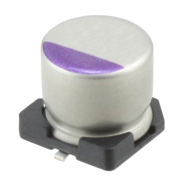
Vishay OS-CON
SMD Aluminum Solid Capacitors with Conductive Polymer
FEATURES
• Vishay OS-CON series utilizes a polymerized
organic semiconductor as electrolyte
• Features superior heat-proof characteristics
compared with previous OS-CON series
• For power supply and other applications where
high ripple current and low impedance are necessary
• Rated ripple current values are guaranteed at 105 °C
• No need to consider derating on maximum allowable
ripple current
• SMD version with base plate, containing no lead (Pb)
• Material categorization: For definitions of compliance
please see www.vishay.com/doc?99912
QUICK REFERENCE DATA
DESCRIPTION
Operating temperature range
Capacitance tolerance at 120 Hz
Tangent of loss angle (tan ) at 120 Hz
Leakage current (μA/2 min) (or less) (1)
Equivalent series resistance (), (100 kHz to 300 kHz)
VALUE
-55 °C to +105 °C
M: ± 20 %
Values in Electrical Data and Ordering Information table
Values in Electrical Data and Ordering Information table
Values in Electrical Data and Ordering Information table
0.75 to 1.25
-55 °C
Z/Z20 °C
+105 °C
Z/Z20 °C
0.75 to 1.25
C/C
Within ± 20 %
tan
1.5 x the value of tangent of loss angle
ESR
1.5 x the value of ESR
Leakage current
the value of leakage current
C/C
Within ± 20 %
tan
1.5 x the value of tangent of loss angle
ESR
1.5 x the value of ESR
Leakage current
the value of leakage current after voltage treatment
Temporary: < 20 % of the rated voltage
Continuous: < 10 % of the rated voltage
Characteristics at high temp. and low temp.
Impedance ratio at 100 kHz, +20 °C
Endurance +105 °C, 2000 h
Rated voltage applied (20 V for 25 V products)
(1000 h for A5/B6 sizes)
Damp heat (steady state)
(+60 °C, 90 % to 95 % RH, 1000 h, no voltage)
(500 h for A5/B6 sizes)
Reverse voltage guarantee
Solder heat resistance (VPS) (2)
(230 °C x 75 s)
(Please consult us for A5/B6 sizes)
C/C
Within ± 10 %
tan
1.3 x the value of tangent of loss angle
ESR
1.3 x the value of ESR
Leakage current
the value of leakage current after voltage treatment
Notes
(1) If any doubt arises, measure the current after applying voltage (voltage treatment). Voltage treatment: The rated voltage is applied to Vishay
OS-CON (2.5 WV to 20 WV) for 120 min at 105 °C. (However, 20 V is applied to a 25 WV Vishay OS-CON).
(2) Refer to Soldering Profile and Land Pattern document www.vishay.com/doc?90014 for soldering recommendation.
DIMENSIONS in millimeters
SIZE CODE
0.2 max.
W
H
ØD
L
Revision: 06-Mar-14
P
R
(+)
C
A5
B6
C6
E7
F8
E12
F12
ØD
± 0.5
4.0
5.0
6.3
8.0
10.0
8.0
10.0
L
max.
5.5
6.0
6.0
7.0
8.0
12.0
12.7
W
± 0.2
4.3
5.3
6.6
8.3
10.3
8.3
10.3
H
± 0.2
4.3
5.3
6.6
8.3
10.3
8.3
10.3
C
± 0.2
5.0
6.0
7.3
9.0
11.0
9.0
11.0
R
0.5 to 0.8
0.5 to 0.8
0.5 to 0.8
0.5 to 0.8
0.5 to 0.8
0.8 to 1.1
0.8 to 1.1
P
± 0.2
1.0
1.4
2.1
3.2
4.6
3.2
4.6
Document Number: 90021
1
For technical questions, contact: aluminumcaps4@vishay.com
THIS DOCUMENT IS SUBJECT TO CHANGE WITHOUT NOTICE. THE PRODUCTS DESCRIBED HEREIN AND THIS DOCUMENT
ARE SUBJECT TO SPECIFIC DISCLAIMERS, SET FORTH AT www.vishay.com/doc?91000
�94SVP
www.vishay.com
Vishay OS-CON
RECOMMENDED LAND PATTERN DIMENSIONS in millimeters
SIZE CODE
a
b
c
A5
1.0
6.2
1.6
B6
1.4
7.4
1.6
C6
2.1
9.1
1.6
a
E7
2.8
11.1
1.9
b
F8
4.3
13.1
1.9
c
E12
2.8
11.1
1.9
F12
4.3
13.1
1.9
CASE CODE LIST
CAPACITANCE
(μF)
WV (1)
(SV)
(2)
2.5
4
6.3
10
16
20
25
(3.3)
(5.2)
(8.2)
(11.5)
(18.4)
(23)
(25)
3.3
-
-
-
-
A5
-
-
4.7
-
-
-
A5
-
-
-
6.8
-
-
-
A5
-
-
C6
10.0
-
-
-
A5
-
B6
E7
15.0
-
-vb
-
A5
B6
-
-
22.0
-
-
A5
-
B6
C6
F8
27.0
-
-
-
-
-
C6
-
33.0
-
A5
-
B6
-
E7
E12
39.0
-
B6
-
-
C6
-
-
47.0
-
-
B6
C6
-
E7
-
56.0
-
-
-
C6
E7
F8
F12
68.0
-
B6
-
-
-
F8
-
82.0
-
-
C6
-
E7
-
-
100.0
-
-
C6
-
F8
E12
-
120.0
-
-
-
E7
-
-
-
150.0
-
C6
-
E7, F8
F8
F12
-
180.0
-
-
-
-
E12
-
-
220.0
-
-
E7, F8
-
-
-
-
270.0
-
-
-
F8
-
-
-
330.0
-
E7
F8
E12
F12
-
-
470.0
-
-
F8, E12
-
-
-
-
560.0
-
E12
-
F12
-
-
-
680.0
E12
F8
-
-
-
-
-
820.0
-
-
F12
-
-
-
-
1200.0
-
F12
-
-
-
-
-
1500.0
F12
-
-
-
-
-
-
Notes
(1) WV = Rated Voltage.
(2) (SV) = Surge Voltage (at room temperature). The description contents are subject to change due to technical improvement without notice.
Please ask for latest specifications for order and use.
Revision: 06-Mar-14
Document Number: 90021
2
For technical questions, contact: aluminumcaps4@vishay.com
THIS DOCUMENT IS SUBJECT TO CHANGE WITHOUT NOTICE. THE PRODUCTS DESCRIBED HEREIN AND THIS DOCUMENT
ARE SUBJECT TO SPECIFIC DISCLAIMERS, SET FORTH AT www.vishay.com/doc?91000
�94SVP
www.vishay.com
Vishay OS-CON
ELECTRICAL DATA AND ORDERING INFORMATION
UR
(V)
2.5
4
6.3
10
16
20
25 (2)
CR
(μF)
CASE
CODE
MAX. ESR
(100 kHz to 300 kHz)
(m)
680
1500
33
39
68
150
330
680
560
1200
22
47
82
100
220
220
330
470
470
820
4.7
6.8
10
15
33
47
56
120
150
150
270
330
560
3.3
15
22
39
56
82
100
150
180
330
10
22
27
33
47
56
68
100
150
6.8
10
22
33
56
E12
F12
A5
B6
B6
C6
E7
F8
E12
F12
A5
B6
C6
C6
E7
F8
F8
E12
F8
F12
A5
A5
A5
A5
B6
C6
C6
E7
E7
F8
F8
E12
F12
A5
B6
B6
C6
E7
E7
F8
F8
E12
F12
B6
C6
C6
E7
E7
F8
F8
E12
F12
C6
E7
F8
E12
F12
16
13
200
70
70
50
35
25
16
13
220
90
50
40
35
30
25
17
25
14
260
260
240
240
130
60
55
40
35
35
30
19
15
280
150
120
65
50
45
40
35
22
17
170
65
60
50
50
45
45
25
21
80
60
50
30
28
ALLOWABLE
RIPPLE CURRENT
AT 100 kHz, +105 °C
(mA)
4080
5230
740
1100
1100
1620
2560
3700
4080
5230
700
1060
1570
1810
2560
3020
3300
3960
3700
5040
660
660
670
700
990
1450
1510
2120
2560
2670
3020
3740
4870
590
920
980
1390
1800
1890
2400
2670
3480
4580
850
1390
1450
1700
1750
2200
2200
3260
4220
1200
1500
2000
2980
3800
MAX.
TANGENT OF
LOSS ANGLE
0.15
0.18
0.15
0.12
0.12
0.12
0.12
0.12
0.15
0.18
0.12
0.12
0.12
0.12
0.12
0.12
0.12
0.15
0.12
0.15
0.08
0.09
0.10
0.10
0.15
0.12
0.12
0.12
0.12
0.12
0.12
0.15
0.15
0.07
0.10
0.10
0.10
0.12
0.12
0.12
0.12
0.15
0.15
0.10
0.10
0.10
0.12
0.12
0.12
0.12
0.15
0.15
0.10
0.10
0.10
0.12
0.12
MAX. LEAKAGE
CURRENT
(μA)
(after 2 min)
340
750
66.0
78
136
120
264
544
448
960
69.3
148
103
126
277
277
416
592
592
775
23.5
34.0
50.0
75.0
165
94
112
240
300
300
540
660
840
26.4
120
176
125
179
262
320
480
576
792
100
88
108
132
188
224
272
400
600
85
125
275
413
700
PART NUMBER (1)
94SVP687X02R5E12
94SVP158X02R5F12
94SVP336X0004A5
94SVP396X0004B6
94SVP686X0004B6
94SVP157X0004C6
94SVP337X0004E7
94SVP687X0004F8
94SVP567X0004E12
94SVP128X0004F12
94SVP226X06R3A5
94SVP476X06R3B6
94SVP826X06R3C6
94SVP107X06R3C6
94SVP227X06R3E7
94SVP227X06R3F8
94SVP337X06R3F8
94SVP477X06R3E12
94SVP477X06R3F8
94SVP827X06R3F12
94SVP475X0010A5
94SVP685X0010A5
94SVP106X0010A5
94SVP156X0010A5
94SVP336X0010B6
94SVP476X0010C6
94SVP566X0010C6
94SVP127X0010E7
94SVP157X0010E7
94SVP157X0010F8
94SVP277X0010F8
94SVP337X0010E12
94SVP567X0010F12
94SVP335X0016A5
94SVP156X0016B6
94SVP226X0016B6
94SVP396X0016C6
94SVP566X0016E7
94SVP826X0016E7
94SVP107X0016F8
94SVP157X0016F8
94SVP187X0016E12
94SVP337X0016F12
94SVP106X0020B6
94SVP226X0020C6
94SVP276X0020C6
94SVP336X0020E7
94SVP476X0020E7
94SVP566X0020F8
94SVP686X0020F8
94SVP107X0020E12
94SVP157X0020F12
94SVP685X0025C6 (2)
94SVP106X0025E7 (2)
94SVP226X0025F8 (2)
94SVP336X0025E12 (2)
94SVP566X0025F12 (2)
Notes
(1) Part numbers shown are for ± 20 % capacitance tolerance (X0).
(2) 25 V rated parts are not for new design. Please check 94SVPD (www.vishay.com/doc?90022) for replacement.
Revision: 06-Mar-14
Document Number: 90021
3
For technical questions, contact: aluminumcaps4@vishay.com
THIS DOCUMENT IS SUBJECT TO CHANGE WITHOUT NOTICE. THE PRODUCTS DESCRIBED HEREIN AND THIS DOCUMENT
ARE SUBJECT TO SPECIFIC DISCLAIMERS, SET FORTH AT www.vishay.com/doc?91000
�Legal Disclaimer Notice
www.vishay.com
Vishay
Disclaimer
ALL PRODUCT, PRODUCT SPECIFICATIONS AND DATA ARE SUBJECT TO CHANGE WITHOUT NOTICE TO IMPROVE
RELIABILITY, FUNCTION OR DESIGN OR OTHERWISE.
Vishay Intertechnology, Inc., its affiliates, agents, and employees, and all persons acting on its or their behalf (collectively,
“Vishay”), disclaim any and all liability for any errors, inaccuracies or incompleteness contained in any datasheet or in any other
disclosure relating to any product.
Vishay makes no warranty, representation or guarantee regarding the suitability of the products for any particular purpose or
the continuing production of any product. To the maximum extent permitted by applicable law, Vishay disclaims (i) any and all
liability arising out of the application or use of any product, (ii) any and all liability, including without limitation special,
consequential or incidental damages, and (iii) any and all implied warranties, including warranties of fitness for particular
purpose, non-infringement and merchantability.
Statements regarding the suitability of products for certain types of applications are based on Vishay’s knowledge of typical
requirements that are often placed on Vishay products in generic applications. Such statements are not binding statements
about the suitability of products for a particular application. It is the customer’s responsibility to validate that a particular
product with the properties described in the product specification is suitable for use in a particular application. Parameters
provided in datasheets and/or specifications may vary in different applications and performance may vary over time. All
operating parameters, including typical parameters, must be validated for each customer application by the customer’s
technical experts. Product specifications do not expand or otherwise modify Vishay’s terms and conditions of purchase,
including but not limited to the warranty expressed therein.
Except as expressly indicated in writing, Vishay products are not designed for use in medical, life-saving, or life-sustaining
applications or for any other application in which the failure of the Vishay product could result in personal injury or death.
Customers using or selling Vishay products not expressly indicated for use in such applications do so at their own risk. Please
contact authorized Vishay personnel to obtain written terms and conditions regarding products designed for such applications.
No license, express or implied, by estoppel or otherwise, to any intellectual property rights is granted by this document or by
any conduct of Vishay. Product names and markings noted herein may be trademarks of their respective owners.
Material Category Policy
Vishay Intertechnology, Inc. hereby certifies that all its products that are identified as RoHS-Compliant fulfill the
definitions and restrictions defined under Directive 2011/65/EU of The European Parliament and of the Council
of June 8, 2011 on the restriction of the use of certain hazardous substances in electrical and electronic equipment
(EEE) - recast, unless otherwise specified as non-compliant.
Please note that some Vishay documentation may still make reference to RoHS Directive 2002/95/EC. We confirm that
all the products identified as being compliant to Directive 2002/95/EC conform to Directive 2011/65/EU.
Vishay Intertechnology, Inc. hereby certifies that all its products that are identified as Halogen-Free follow Halogen-Free
requirements as per JEDEC JS709A standards. Please note that some Vishay documentation may still make reference
to the IEC 61249-2-21 definition. We confirm that all the products identified as being compliant to IEC 61249-2-21
conform to JEDEC JS709A standards.
Revision: 02-Oct-12
1
Document Number: 91000
�