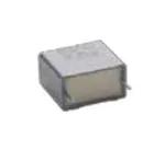
Not for New Designs - Alternative Device: MKP338 1 X1
MKP336 1 X1
www.vishay.com
Vishay BCcomponents
Interference Suppression Film Capacitors
MKP Radial Potted Type
FEATURES
• 15 mm to 27.5 mm lead pitch.
Supplied in box, taped on ammopack or reel
• Material categorization:
for definitions of compliance please see
www.vishay.com/doc?99912
APPLICATIONS
X1 class
For X1 electromagnetic interference suppression in across
the line applications (50 Hz / 60 Hz) with a maximum mains
voltage of 275 VAC.
For application limitations please refer to section
“Application Notes”.
QUICK REFERENCE DATA
Capacitance range (E12 series)
Capacitance tolerance
Rated AC voltage
Permissible DC voltage
Climatic testing class (according to EN 60068-1)
Maximum application temperature
Rated temperature
Leads
0.01 μF to 1 μF (preferred values according to E6)
± 20 %; ± 10 %; ± 5 %
275 VAC; 50 Hz to 60 Hz
630 VDC
55/105/56/B
105 °C
105 °C
Tinned wire
IEC 60384-14:2013
IEC 60384-14:2013 / AMD1:2016
EN 60384-14:2013 + AMD1:2016
IEC 60065, pass. flamm. class B
UL 60384-14
CSA E384-14
Reference standards
Dielectric
Electrodes
Polypropylene film
Metallized film
Mono construction
Construction
Encapsulation
Plastic case, epoxy resin sealed, flame retardant UL-class 94 V-0
Marking
C-value; tolerance; rated voltage; sub-class; manufacturer’s type;
code for dielectric material; manufacturer location, year and week;
manufacturer’s logo or name; safety approvals
Note
• For more detailed data and test requirements, contact rfi@vishay.com
DIMENSIONS in millimeters
W
L
H
lt
P ± 0.4
Revision: 15-Dec-2021
Ø dt
Document Number: 28117
1
For technical questions, contact: rfi@vishay.com
THIS DOCUMENT IS SUBJECT TO CHANGE WITHOUT NOTICE. THE PRODUCTS DESCRIBED HEREIN AND THIS DOCUMENT
ARE SUBJECT TO SPECIFIC DISCLAIMERS, SET FORTH AT www.vishay.com/doc?91000
�Not for New Designs - Alternative Device: MKP338 1 X1
MKP336 1 X1
www.vishay.com
Vishay BCcomponents
COMPOSITION OF CATALOG NUMBER
TYPE AND PITCHES
MULTIPLIER
(nF)
15.0 mm
22.5 mm
336 1 X1
0.1
CAPACITANCE
(numerically)
27.5 mm
2
1
3
10
4
100
5
Example:
104 = 10 x 10 = 100 nF
BFC2
2222(*)
336 1X XX X
336 1X XX X
(*) Old ordering code
TYPE
PACKAGING
336 1
LEAD CONFIGURATION
C-TOL.
Lead length 3.5 mm ± 0.3 mm
Loose in box
X1
Lead length 25.0 mm ± 2.0 mm
PREFERRED TYPES
BFC2 336 10...
± 20 %
BFC2 336 16...
ON REQUEST
336 1
X1
Loose in box
Taped on reel
Lead length 3.5 mm ± 0.3 mm
Lead length 25.0 mm ± 2.0 mm
H = 18.5 mm; P0 = 12.7 mm;
reel diameter 500 mm
± 10 %
BFC2 336 11...
BFC2 336 17...
± 20 %
BFC2 336 13...
± 10 %
BFC2 336 14...
Note
(1) For detailed tape specifications refer to packaging information: www.vishay.com/doc?28139
SPECIFIC REFERENCE DATA
DESCRIPTION
VALUE
Tangent of loss angle:
at 10 kHz
C ≤ 100 nF
≤ 10 x 10-4
100 nF < C ≤ 470 nF
≤ 20 x 10-4
C > 470 nF
≤ 70 x 10-4
Rated voltage pulse slope (dU/dt)R at 385 VDC:
P = 15 mm
250 V/μs
P = 22.5 mm
150 V/μs
P = 27.5 mm
R between leads, for C ≤ 0.33 μF at 100 V; 1 min
RC between leads, for C > 0.33 μF at 100 V; 1 min
100 V/μs
> 15 000 MΩ
> 5000 s
R between leads and case; 100 V; 1 min
> 30 000 MΩ
Withstanding (DC) voltage (cut off current 10 mA) (1); rise time ≤ 1000 V/s
3400 V; 1 min
Withstanding (AC) voltage between leads and case
2050 V; 1 min
Note
(1) See “Voltage Proof Test for Metalized Film Capacitors”: www.vishay.com/doc?28169
Revision: 15-Dec-2021
Document Number: 28117
2
For technical questions, contact: rfi@vishay.com
THIS DOCUMENT IS SUBJECT TO CHANGE WITHOUT NOTICE. THE PRODUCTS DESCRIBED HEREIN AND THIS DOCUMENT
ARE SUBJECT TO SPECIFIC DISCLAIMERS, SET FORTH AT www.vishay.com/doc?91000
�Not for New Designs - Alternative Device: MKP338 1 X1
MKP336 1 X1
www.vishay.com
Vishay BCcomponents
ELECTRICAL DATA AND ORDERING INFORMATION
CATALOG NUMBER BFC2 336 1 ..... AND PACKAGING
LOOSE IN BOX
URAC
(V)
CAP.
(μF)
0.010
0.015
0.022
0.033
0.047
0.068
0.100
0.10
0.15
0.22
0.22
0.33
0.47
0.68
1.00
275
0.010
0.012
0.015
0.018
0.022
0.027
0.033
0.039
0.047
0.056
0.068
0.082
0.10
0.12
0.15
0.18
0.22
0.27
0.33
0.39
0.47
0.56
0.68
0.82
DIMENSIONS
WxHxL
(mm)
MASS
(g) (1)
lt = 3.5 mm ± 0.3 mm
lt = 25.0 mm ± 2.0 mm
REEL
500 mm (1)(2)
H = 18.5 mm;
P0 = 12.7 mm
LAST 5 DIGITS
LAST 5 DIGITS
LAST 5 DIGITS
OF CATALOG
SPQ
OF CATALOG
SPQ
OF CATALOG
NUMBER
NUMBER
NUMBER
PITCH = 15.0 mm ± 0.4 mm; dt = 0.6 mm ± 0.06 mm; URAC = 275 V; C-TOL. = ± 20 %
19001
19007
19002
5.0 x 11.0 x 17.5
1
10153
16153
13153
1000
1000
10223
16223
13223
6.0 x 12.0 x 17.5
1.4
10333
16333
13333
PITCH = 15.0 mm ± 0.4 mm; dt = 0.8 mm ± 0.08 mm; URAC = 275 V; C-TOL. = ± 20 %
7.0 x 13.5 x 17.5
1.8
10473
16473
13473
1000
8.5 x 15.0 x 17.5
2.4
10683
16683
500
13683
10.0 x 16.5 x 17.5
3
10104
500
16104
13104
PITCH = 22.5 mm ± 0.4 mm; dt = 0.8 mm ± 0.08 mm; URAC = 275 V; C-TOL. = ± 20 %
7.0 x 16.5 x 26.0
2.9
19003
19008
19004
8.5 x 18.0 x 26.0
3.8
10154
200
16154
500
13154
10.0 x 19.5 x 26.0
6.8
10224
16224
13224
PITCH = 27.5 mm ± 0.4 mm; dt = 0.8 mm ± 0.08 mm; URAC = 275 V; C-TOL. = ± 20 %
11.0 x 21.0 x 31.0
7.4
19005
19009
13.0 x 23.0 x 31.0
9.2
10334
16334
100
125
15.0 x 25.0 x 31.0
12.3
10474
16474
18.0 x 28.0 x 31.0
16.1
10684
16684
21.0 x 31.0 x 31.0
20.3
10105
50
16105
75
PITCH = 15.0 mm ± 0.4 mm; dt = 0.6 mm ± 0.06 mm; URAC = 275 V; C-TOL. = ± 10 %
11103
17103
14103
11123
17123
14123
5.0 x 11.0 x 17.5
1
11153
17153
14153
1000
1000
11183
17183
14183
11223
17223
14223
6.0 x 12.0 x 17.5
1.4
11273
17273
14273
PITCH = 15.0 mm ± 0.4 mm; dt = 0.8 mm ± 0.08 mm; URAC = 275 V; C-TOL. = ± 10 %
11333
17333
14333
7.0 x 13.5 x 17.5
1.8
11393
17393
14393
1000
11473
17473
14473
500
8.5 x 15.0 x 17.5
2.4
11563
17563
14563
11683
17683
14683
10.0 x 16.5 x 17.5
3
500
11823
17823
14823
PITCH = 22.5 mm ± 0.4 mm; dt = 0.8 mm ± 0.08 mm; URAC = 275 V; C-TOL. = ± 10 %
7.0 x 16.5 x 26.0
2.9
11104
17104
500
14104
11124
17124
14124
200
8.5 x 18.0 x 26.0
3.8
250
11154
17154
14154
10.0 x 19.5 x 26.0
6.8
11184
17184
500
14184
PITCH = 27.5 mm ± 0.4 mm; dt = 0.8 mm ± 0.08 mm; URAC = 275 V; C-TOL. = ± 10 %
11224
17224
11.0 x 21.0 x 31.0
7.4
11274
17274
13.0 x 23.0 x 31.0
9.2
11334
17334
11394
100
17394
125
15.0 x 25.0 x 31.0
12.3
11474
17474
11564
17564
18.0 x 28.0 x 31.0
16.1
11684
17684
21.0 x 31.0 x 31.0
20.3
11824
50
17824
75
SPQ
1100
900
800
650
600
550
450
400
1100
900
800
650
600
550
450
400
Notes
• SPQ = Standard Packing Quantity
(1) Reel diameter = 356 mm is available on request
(2) H = In tape height; P = Sprocket hole distance; for detailed specifications refer to Packaging Information.
0
(3) Weight for short lead product only
Revision: 15-Dec-2021
Document Number: 28117
3
For technical questions, contact: rfi@vishay.com
THIS DOCUMENT IS SUBJECT TO CHANGE WITHOUT NOTICE. THE PRODUCTS DESCRIBED HEREIN AND THIS DOCUMENT
ARE SUBJECT TO SPECIFIC DISCLAIMERS, SET FORTH AT www.vishay.com/doc?91000
�Not for New Designs - Alternative Device: MKP338 1 X1
MKP336 1 X1
www.vishay.com
Vishay BCcomponents
APPROVALS
SAFETY APPROVALS X1
VOLTAGE
VALUE
FILE NUMBERS
LINKS
EN 60384-14 (ENEC)
(= IEC 60384-14 ed-4 (2013))
275 VAC
10 nF to 1 μF
ENEC16/FI/21/01061
www.vishay.com/doc?28197
UL 60384-14
275 VAC
10 nF to 1 μF
E354331
CSA E384-14
275 VAC
10 nF to 1 μF
E354331
CB-Test-Certificate
275 VAC
10 nF to 1 μF
FI-39828/A1
www.vishay.com/doc?28188
www.vishay.com/doc?28198
The ENEC-approval together with the CB-Certificate replace all national marks of the following countries (they have already signed the
ENEC-Agreement): Austria; Belgium; Czech. Republic; Denmark; Finland; France; Germany; Greece; Hungary; Ireland; Italy; Luxembourg;
Netherlands; Norway; Portugal; Slovenian; Spain; Switzerland and United Kingdom.
MOUNTING
Normal Use
The capacitors are designed for mounting on printed-circuit boards. The capacitors packed in bandoleers are designed for
mounting in printed-circuit boards by means of automatic insertion machines.
For detailed tape specifications refer to “Packaging information”.
Specific Method of Mounting to Withstand Vibration and Shock
In order to withstand vibration and shock tests, it must be ensured that the stand-off pips are in good contact with the
printed-circuit board:
• For pitches ≤ 15 mm capacitors shall be mechanically fixed by the leads
• For longer pitches the capacitors shall be mounted in the same way and the body clamped
Space Requirements on Printed Circuit Board
The maximum length and width of film capacitors is shown in Figure:
• Eccentricity as in figure. The maximum eccentricity is smaller than or equal to the lead diameter of the product concerned
• Product height with seating plane as given by “IEC 60717” as reference: hmax. ≤ h + 0.3 mm
bmax. = b + 0.3 mm
Eccentricity
lmax. = I + 0.3 mm
CBA116
SOLDERING CONDITIONS
For general soldering conditions and wave soldering profile, we refer to the application note:
“Soldering Guidelines for Film Capacitors”: www.vishay.com/doc?28171
Storage Temperature
Tstg = -25 °C to +35 °C with RH maximum 75 % without condensation
Ratings and Characteristics Reference Conditions
Unless otherwise specified, all electrical values apply to an ambient temperature of 23 °C ± 1 °C, an atmospheric pressure of
86 kPa to 106 kPa and a relative humidity of 50 % ± 2 %.
For reference testing, a conditioning period shall be applied over 96 h ± 4 h by heating the products in a circulating air oven at
the rated temperature and a relative humidity not exceeding 20 %.
Revision: 15-Dec-2021
Document Number: 28117
4
For technical questions, contact: rfi@vishay.com
THIS DOCUMENT IS SUBJECT TO CHANGE WITHOUT NOTICE. THE PRODUCTS DESCRIBED HEREIN AND THIS DOCUMENT
ARE SUBJECT TO SPECIFIC DISCLAIMERS, SET FORTH AT www.vishay.com/doc?91000
�Not for New Designs - Alternative Device: MKP338 1 X1
MKP336 1 X1
www.vishay.com
Vishay BCcomponents
CHARACTERISTICS
Axis Title
Axis Title
10000
Typical
1st line
2nd line
2nd line
ΔC/C (%)
1000
0
Maximum
-2
100
-4
C = 1 μF
100
1000
220 nF < C < 1 μF
1st line
2nd line
2
10000
1000
2nd line
Dissipation Factor (x 10-4)
4
47 nF < C ≤ 220 nF
10 nF < C ≤ 47 nF
100
10
C ≤ 10 nF
Minimum
10
-6
-50
0
50
1
100
10
100
1000
10 000
Ambient Temperature (°C)
Frequency (Hz)
Capacitance
Tangent of loss angle
10
100 000
Axis Title
Axis Title
10000
1000
100
10000
10
1000
1 nF
4.7 nF
1
100 nF
470 nF
100
1st line
2nd line
1000
10
2nd line
Frequency (MHz)
10 nF
47 nF
1st line
2nd line
2nd line
Impedance (Ω)
100
X1
100
1
1000 nF
0.1
0.01
10 000
100 000
1M
10M
10
100M
10
10 000
0.1
1
10
100
1000
Frequency (Hz)
Capacitance (nF)
Impedance
Resonant frequency
Axis Title
Axis Title
1000
10000
10000
10 000
100
1000
1000 nF
100
470 nF
100 nF
10
47 nF
10 nF
1000
1st line
2nd line
100
2nd line
AC Current (mA)
1000
1st line
2nd line
2nd line
AC Voltage (V)
Tamb ≤ 100 °C
100
4.7 nF
1
1 nF
Tamb ≤ 105 °C
10
10
100
Revision: 15-Dec-2021
1000
10 000
10
100 000
0.1
10
100
1000
10 000
Frequency (Hz)
Frequency (Hz)
Max. RMS voltage
AC current (sinewave)
10
100 000
Document Number: 28117
5
For technical questions, contact: rfi@vishay.com
THIS DOCUMENT IS SUBJECT TO CHANGE WITHOUT NOTICE. THE PRODUCTS DESCRIBED HEREIN AND THIS DOCUMENT
ARE SUBJECT TO SPECIFIC DISCLAIMERS, SET FORTH AT www.vishay.com/doc?91000
�Not for New Designs - Alternative Device: MKP338 1 X1
MKP336 1 X1
www.vishay.com
Vishay BCcomponents
Axis Title
1 000 000
10000
RC (s)
1st line
1st line
2nd line
1000
100 000
100
10
10 000
0
20
40
60
80
100
Tamb (°C)
Capacitance
APPLICATION NOTES
• For X2 electromagnetic interference suppression in standard across the line applications (50 Hz / 60 Hz) with a maximum
mains voltage of 310 VAC
• For series impedance applications we refer to application note www.vishay.com/doc?28153
• For capacitors connected in parallel, normally the proof voltage and possibly the rated voltage must be reduced. For
information depending of the capacitance value and the number of parallel connections contact: dc-film@vishay.com
• These capacitors are not intended for continuous pulse application. For these situations capacitors of the AC and pulse
programs must be used
• The maximum ambient temperature must not exceed 110 °C. (125 °C for less than 1000 h) for C ≤ 470 nF and 110 °C for
C > 470 nF
• Rated voltage pulse slope:
If the pulse voltage is lower than the rated voltage, the values of the specific reference data can be multiplied by 435 VDC and
divided by the applied voltage
INSPECTION REQUIREMENTS
General Notes
Sub-clause numbers of tests and performance requirements refer to the “Sectional Specification, Publication
IEC 60384-14 ed-4 (2013) and Specific Reference Data.”
GROUP C INSPECTION REQUIREMENTS
SUB-CLAUSE NUMBER
AND TEST
SUB-GROUP C1A PART OF SAMPLE
OF SUB-GROUP C1
D
OR
ND
CONDITIONS
D
4.1 Dimensions (detail)
As specified in chapters “General Data” of
this specification
Initial measurements
Capacitance
Tangent of loss angle:
For C ≤ 470 nF at 100 kHz
For C > 470 nF at 10 kHz
4.3 Robustness of terminations
Tensile: load 10 N; 10 s
Bending: load 5 N; 4 x 90°
Revision: 15-Dec-2021
PERFORMANCE REQUIREMENTS
No visible damage
Document Number: 28117
6
For technical questions, contact: rfi@vishay.com
THIS DOCUMENT IS SUBJECT TO CHANGE WITHOUT NOTICE. THE PRODUCTS DESCRIBED HEREIN AND THIS DOCUMENT
ARE SUBJECT TO SPECIFIC DISCLAIMERS, SET FORTH AT www.vishay.com/doc?91000
�Not for New Designs - Alternative Device: MKP338 1 X1
MKP336 1 X1
www.vishay.com
Vishay BCcomponents
GROUP C INSPECTION REQUIREMENTS
SUB-CLAUSE NUMBER
AND TEST
SUB-GROUP C1A PART OF SAMPLE
OF SUB-GROUP C1
4.4
D
OR
ND
CONDITIONS
PERFORMANCE REQUIREMENTS
D
Resistance to soldering heat
No pre-drying
Method: 1A
Solder bath: 260 °C
Duration: 10 s
4.19 Component solvent resistance
Isopropylalcohol at room temperature
Method: 2
Immersion time: 5 min ± 0.5 min
Recovery time:
Min. 1 h, max. 2 h
4.4.2 Final measurements
Visual examination
No visible damage
Legible marking
Capacitance
|ΔC/C| ≤ 5 % of the value measured
initially
Tangent of loss angle
Increase of tan δ: ≤ 0.008
Compared to values measured initially
Insulation resistance
As specified in section “Insulation
Resistance” of this specification
Initial measurements
Capacitance
Tangent of loss angle:
For C ≤ 470 nF at 100 kHz
For C > 470 nF at 10 kHz
No visible damage
Legible marking
4.20 Solvent resistance of the marking:
see section “General Notes”; item 5
Isopropylalcohol at room temperature
Method: 1
Rubbing material: cotton wool
Immersion time: 5 min ± 0.5 min
No visible damage
4.6
θA = - 55 °C
θB = + 105 °C
5 cycles
SUB-GROUP C1B PART OF SAMPLE
OF SUB-GROUP C1
D
Rapid change of temperature
SUB-GROUP C1B PART OF SAMPLE
OF SUB-GROUP C1
D
4.6.1 Inspection
Duration t = 30 min
4.7
Visual examination
Mounting: see section “Mounting” of this
specification
Procedure B4:
Frequency range: 10 Hz to 55 Hz
Amplitude: 0.75 mm or
Acceleration 98 m/s2
(whichever is less severe)
Total duration 6 h
No visible damage
Visual examination
No visible damage
Vibration (see note 3.1)
4.7.2 Final inspection
Revision: 15-Dec-2021
Document Number: 28117
7
For technical questions, contact: rfi@vishay.com
THIS DOCUMENT IS SUBJECT TO CHANGE WITHOUT NOTICE. THE PRODUCTS DESCRIBED HEREIN AND THIS DOCUMENT
ARE SUBJECT TO SPECIFIC DISCLAIMERS, SET FORTH AT www.vishay.com/doc?91000
�Not for New Designs - Alternative Device: MKP338 1 X1
MKP336 1 X1
www.vishay.com
Vishay BCcomponents
GROUP C INSPECTION REQUIREMENTS
SUB-CLAUSE NUMBER
AND TEST
SUB-GROUP C1B PART OF SAMPLE
OF SUB-GROUP C1
4.9
Shock (see note 3)
4.9.2
D
OR
ND
PERFORMANCE REQUIREMENTS
D
Mounting: See section “Mounting” for
more information
Pulse shape: Half sine
Acceleration: 490 m/s2
Duration of pulse: 11 ms
Final measurements
SUB-GROUP C1 COMBINED SAMPLE
OF SPECIMENS OF
SUB-GROUPS C1A AND C1B
4.11 Climatic sequence
CONDITIONS
Visual examination
No visible damage
Capacitance
|ΔC/C| ≤ 5 % of the value measured
initially
Tangent of loss angle
Increase of tan δ: ≤ 0.008
Compared to values measured initially
Insulation resistance
As specified in section “Insulation
Resistance” of this specification
D
4.11.1 Initial measurements
Capacitance
Measured in 4.4.2 and 4.9.2
Tangent of loss angle:
Measured initially in C1A and C1B
4.11.2 Dry heat
Temperature: 105 °C
Duration: 16 h
4.11.3 Damp heat cyclic
Test Db
First cycle
4.11.4 Cold
4.11.5 Damp heat cyclic
Test Db
remaining cycles
SUB-GROUP C1 COMBINED SAMPLE
OF SPECIMENS OF
SUB-GROUPS C1A AND C1B
4.11.6 Final measurements
Revision: 15-Dec-2021
Temperature: - 55 °C
Duration: 2 h
D
Visual examination
No visible damage
Legible marking
Capacitance
|ΔC/C| ≤ 5 % of the value measured in
4.11.1.
Tangent of loss angle
Increase of tan δ: ≤ 0.008 compared to
values measured in 4.11.1
Voltage proof
1200 VDC; 1 min between term
No permanent breakdown or flash-over
Insulation resistance
≥ 50 % of values specified in section
“Insulation Resistance” of this
specification
Document Number: 28117
8
For technical questions, contact: rfi@vishay.com
THIS DOCUMENT IS SUBJECT TO CHANGE WITHOUT NOTICE. THE PRODUCTS DESCRIBED HEREIN AND THIS DOCUMENT
ARE SUBJECT TO SPECIFIC DISCLAIMERS, SET FORTH AT www.vishay.com/doc?91000
�Not for New Designs - Alternative Device: MKP338 1 X1
MKP336 1 X1
www.vishay.com
Vishay BCcomponents
GROUP C INSPECTION REQUIREMENTS
SUB-CLAUSE NUMBER
AND TEST
SUB-GROUP C2
4.12
D
OR
ND
CONDITIONS
PERFORMANCE REQUIREMENTS
D
Damp heat steady state
56 days, 40 °C, 90 % to 95 % RH,
no load capacitance
4.12.1 Initial measurements
Tangent of loss angle at 10 kHz
4.12.3 Final measurements
Visual examination
No visible damage
Legible marking
Capacitance
|ΔC/C| ≤ 5 % of the value measured in
4.12.1.
Tangent of loss angle
Increase of tan δ: ≤ 0.008
Compared to values measured in 4.12.1.
Voltage proof
1200 VDC; 1 min between term
No permanent breakdown or flash-over
Insulation resistance
≥ 50 % of values specified in section
“Insulation Resistance” of this
specification
SUB GROUP C3
D
4.13.1 Initial measurements
Capacitance
Tangent of loss angle:
For C ≤ 470 nF at 100 kHz
For C > 470 nF at 10 kHz
4.13
Impulse voltage
3 successive impulses, full wave, peak
voltage:
X1: 4 kV
Max. 24 pulses
4.14
Endurance
Duration: 1000 h
1.25 URAC at 105 °C
Once in every hour the voltage is
increased to 1000 VRMS for 0.1 s via
resistor of 47 Ω ± 5 %
SUB GROUP C3
4.14.7 Final measurements
No selfhealing breakdowns or flashover
D
Visual examination
No visible damage
Legible marking
Capacitance
|ΔC/C| ≤ 10 % compared to values
measured in 4.13.1.
Tangent of loss angle
Increase of tan δ: ≤ 0.008
Compared to values measured in 4.13.1.
Voltage proof
No permanent breakdown or flash-over
1200 VDC; 1 min between terminations
2050 VDC; 1 min between terminations
and case
Insulation resistance
Revision: 15-Dec-2021
≥ 50 % of values specified in section
“Insulation Resistance” of this
specification
Document Number: 28117
9
For technical questions, contact: rfi@vishay.com
THIS DOCUMENT IS SUBJECT TO CHANGE WITHOUT NOTICE. THE PRODUCTS DESCRIBED HEREIN AND THIS DOCUMENT
ARE SUBJECT TO SPECIFIC DISCLAIMERS, SET FORTH AT www.vishay.com/doc?91000
�Not for New Designs - Alternative Device: MKP338 1 X1
MKP336 1 X1
www.vishay.com
Vishay BCcomponents
GROUP C INSPECTION REQUIREMENTS
SUB-CLAUSE NUMBER
AND TEST
SUB-GROUP C 4
4.15
D
OR
ND
CONDITIONS
PERFORMANCE REQUIREMENTS
D
Charge and discharge
10 000 cycles
(50 c/s) charge to UR half sinewave
Duration: 5 ms
Discharge resistance:
385 V DC
R = ------------------------------------------1.5 x C ( dU ⁄ dt )
Rmin. = 2.2
4.15.1 Initial measurements
Capacitance
Tangent of loss angle
For C ≤ 470 nF at 100 kHz
For C > 470 nF at 10 kHz
4.15.3 Final measurements
Capacitance
|ΔC/C| ≤ 10 % compared to values
measured in 4.15.1.
Tangent of loss angle
Increase of tan δ: ≤ 0.008
Compared to values measured in 4.15.1
Insulation resistance
≥ 50 % of values specified in section
“Insulation Resistance” of this
specification
Resonance frequency
As specified in section “Resonant
Frequency” of this specification. ± 10 %
Bore of gas jet: Ø 0.5 mm
Fuel: Butane
Test duration for actual volume V in mm3:
V ≤ 250: 10 s
250 < V ≤ 500: 20 s
500 < V ≤ 1750: 30 s
V > 1750: 60 s
One flame application
After removing test flame from capacitor,
the capacitor must not continue to burn
for more than 10 s. No burning particle
must drop from the sample.
SUB-GROUP C5
4.16
Radio frequency characteristic
SUB-GROUP C6
4.17
D
D
Passive flammability
Class B
12 mm
~ 8 mm
45.0°
SUB-GROUP C7
4.18
Active flammability
D
20 x 4 kV discharges on the test capacitor
connected to UR
The cheese cloth around the capacitors
shall not burn with a flame.
No electrical measurements are required.
Revision: 15-Dec-2021
Document Number: 28117
10
For technical questions, contact: rfi@vishay.com
THIS DOCUMENT IS SUBJECT TO CHANGE WITHOUT NOTICE. THE PRODUCTS DESCRIBED HEREIN AND THIS DOCUMENT
ARE SUBJECT TO SPECIFIC DISCLAIMERS, SET FORTH AT www.vishay.com/doc?91000
�Legal Disclaimer Notice
www.vishay.com
Vishay
Disclaimer
ALL PRODUCT, PRODUCT SPECIFICATIONS AND DATA ARE SUBJECT TO CHANGE WITHOUT NOTICE TO IMPROVE
RELIABILITY, FUNCTION OR DESIGN OR OTHERWISE.
Vishay Intertechnology, Inc., its affiliates, agents, and employees, and all persons acting on its or their behalf (collectively,
“Vishay”), disclaim any and all liability for any errors, inaccuracies or incompleteness contained in any datasheet or in any other
disclosure relating to any product.
Vishay makes no warranty, representation or guarantee regarding the suitability of the products for any particular purpose or
the continuing production of any product. To the maximum extent permitted by applicable law, Vishay disclaims (i) any and all
liability arising out of the application or use of any product, (ii) any and all liability, including without limitation special,
consequential or incidental damages, and (iii) any and all implied warranties, including warranties of fitness for particular
purpose, non-infringement and merchantability.
Statements regarding the suitability of products for certain types of applications are based on Vishay's knowledge of typical
requirements that are often placed on Vishay products in generic applications. Such statements are not binding statements
about the suitability of products for a particular application. It is the customer's responsibility to validate that a particular product
with the properties described in the product specification is suitable for use in a particular application. Parameters provided in
datasheets and / or specifications may vary in different applications and performance may vary over time. All operating
parameters, including typical parameters, must be validated for each customer application by the customer's technical experts.
Product specifications do not expand or otherwise modify Vishay's terms and conditions of purchase, including but not limited
to the warranty expressed therein.
Hyperlinks included in this datasheet may direct users to third-party websites. These links are provided as a convenience and
for informational purposes only. Inclusion of these hyperlinks does not constitute an endorsement or an approval by Vishay of
any of the products, services or opinions of the corporation, organization or individual associated with the third-party website.
Vishay disclaims any and all liability and bears no responsibility for the accuracy, legality or content of the third-party website
or for that of subsequent links.
Except as expressly indicated in writing, Vishay products are not designed for use in medical, life-saving, or life-sustaining
applications or for any other application in which the failure of the Vishay product could result in personal injury or death.
Customers using or selling Vishay products not expressly indicated for use in such applications do so at their own risk. Please
contact authorized Vishay personnel to obtain written terms and conditions regarding products designed for such applications.
No license, express or implied, by estoppel or otherwise, to any intellectual property rights is granted by this document or by
any conduct of Vishay. Product names and markings noted herein may be trademarks of their respective owners.
© 2022 VISHAY INTERTECHNOLOGY, INC. ALL RIGHTS RESERVED
Revision: 01-Jan-2022
1
Document Number: 91000
�