TOS 020016
www.vishay.com
Vishay Draloric
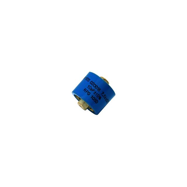
RF Power Barrel Capacitors
with Screw Terminals, Class 1 and Class 2 Ceramic
FEATURES
• Small size
• Geometry minimizes inductance, optimizes voltage
withstand and maximizes heat radiation
APPLICATIONS
• Industrial and medical RF power supply
• Small broadcasting equipment
• Antenna couplers
• Induction heating equipment
CAPACITANCE RANGE
QUICK REFERENCE DATA
10 pF to 2.5 nF
DESCRIPTION
Ceramic Class
Ceramic Dielectric
VALUE
1
2
C0G, U2J, N5600
X7R, Y5U
Type
Voltage (Vp)
TOS 020016
7500
7500
Min. Capacitance (pF)
10
400
Max. Capacitance (pF)
300
2500
Mounting
CAPACITANCE TOLERANCE
• Class 1:
± 10 %
• Class 2:
± 20 %
CERAMIC DIELECTRICS
• Class 1:
C0G, U2J, N5600
• Class 2:
XR7, Y5U
Screw terminal
RATED VOLTAGE
MATERIAL
Capacitor elements made from class 1 ceramic dielectric
with noble metal electrodes.
Connection terminals:
thread terminal, brass, silver plated.
Allowable torque: 1.47 Nm (13 lbf in)
FINISH
Capacitor body completely protective lacquered.
MARKING
Type designator, capacitance value and tolerance, rated
peak voltage, ceramic material code, production date code,
manufacturer logo.
7.5 kVDC
DIELECTRIC STRENGTH TEST
150 % of rated voltage (8000 VRMS, 50 Hz, 3 minutes)
DISSIPATION FACTOR
• C0G, U2J: max. 0.05 % (1 MHz)
• N5600:
max. 0.20 % (1 MHz)
• X7R, Y5U: max. 2.5 % (1 kHz)
INSULATION RESISTANCE
• C0G, U2J, N5600, X7R: min. 100 000 M (at 25 °C)
• Y5U:
min. 50 000 M (at 25 °C)
OPERATING TEMPERATURE RANGE
Revision: 25-Feb-16
• Class 1:
-55 °C to +100 °C
• Class 2:
-55 °C to +85 °C
Document Number: 22086
1
For technical questions, contact: powcap@vishay.com
THIS DOCUMENT IS SUBJECT TO CHANGE WITHOUT NOTICE. THE PRODUCTS DESCRIBED HEREIN AND THIS DOCUMENT
ARE SUBJECT TO SPECIFIC DISCLAIMERS, SET FORTH AT www.vishay.com/doc?91000
�TOS 020016
www.vishay.com
Vishay Draloric
SAP PART NUMBER AND ELECTRICAL DATA
PART NUMBER
CERAMIC
CAP.
VALUES
(pF)
RATED
VOLTAGE
(kVDC)
MAX. POWER RATING (1)
MAX. CURRENT RATING
1.0 MHz
(kvar)
10 MHz
(kvar)
30 MHz
(kvar)
1.0 MHz
(ARMS)
10 MHz
(ARMS)
30 MHz
(ARMS)
BS020016VZ10036AC1
10
1.7
10
10
0.3
2.5
4.3
BS020016VZ15036AC1
15
3.2
10
10
0.6
3.1
5.3
25
4.4
10
10
0.8
4.0
6.9
30
5.3
10
10
1.0
4.4
7.5
BS020016VZ40036AC1
40
7.0
10
10
1.3
5.1
8.7
BS020016VZ50036AC1
50
8.8
10
10
1.7
5.6
9.7
75
10
10
7.0
2.2
6.9
10
100
10
10
5.3
2.5
7.9
10
150
5.0
5.0
3.5
2.2
6.9
10
10
BS020016VZ25036AC1
BS020016VZ30036AC1
BS020016VZ75036AL1
BS020016VZ10136AL1
C0G
(NP0)
U2J
(N750)
BS020016VZ15136AS1
BS020016VZ20136AS1
5.0
5.0
2.7
2.5
7.9
BS020016VZ30136AS1
N5600
200
300
5.0
5.0
1.8
3.1
9.7
10
BS020016VZ40138AT1
400
0.4
0.4
0.4
1.0
3.2
5.5
7.5
BS020016VZ50138AT1
500
0.4
0.4
0.4
1.1
3.6
6.1
BS020016VZ60138AU1
600
0.4
0.4
0.4
1.2
3.9
6.7
BS020016VZ80138AU1
X7R
800
0.4
0.4
0.4
1.4
4.5
7.8
1000
0.2
0.2
0.2
1.1
3.6
6.1
BS020016VZ15238AV1
1500
0.2
0.2
0.2
1.4
4.3
7.5
BS020016VZ20238BA1
2000
0.2
0.2
0.2
1.6
5.0
8.7
2500
0.2
0.2
0.2
1.8
5.6
9.7
BS020016VZ10238AV1
BS020016VZ25238BA1
Y5U
Notes
• # 14th to 15th digit: capacitance tolerance code ± 10 % = 36; ± 20 % = 38
• RoHS-compliant parts on request
(1) The surface temperature during operation must not exceed +100 °C
DIMENSIONS in millimeters (inches)
max. Ø 21
(max. Ø 0.83)
6.0
(0.236)
L2 max. =
6-32 UNC thread
min. 4.8 (0.189) depth
16.0 ± 1.5 (0.630 ± 0.059) (1)
L1 max. = 22.6 (0.890) (1)
Note
Dimension L1 and L2 will vary depending upon capacitance value
(1)
RELATED DOCUMENTS
General Information
Revision: 25-Feb-16
www.vishay.com/doc?22071
Document Number: 22086
2
For technical questions, contact: powcap@vishay.com
THIS DOCUMENT IS SUBJECT TO CHANGE WITHOUT NOTICE. THE PRODUCTS DESCRIBED HEREIN AND THIS DOCUMENT
ARE SUBJECT TO SPECIFIC DISCLAIMERS, SET FORTH AT www.vishay.com/doc?91000
�Legal Disclaimer Notice
www.vishay.com
Vishay
Disclaimer
ALL PRODUCT, PRODUCT SPECIFICATIONS AND DATA ARE SUBJECT TO CHANGE WITHOUT NOTICE TO IMPROVE
RELIABILITY, FUNCTION OR DESIGN OR OTHERWISE.
Vishay Intertechnology, Inc., its affiliates, agents, and employees, and all persons acting on its or their behalf (collectively,
“Vishay”), disclaim any and all liability for any errors, inaccuracies or incompleteness contained in any datasheet or in any other
disclosure relating to any product.
Vishay makes no warranty, representation or guarantee regarding the suitability of the products for any particular purpose or
the continuing production of any product. To the maximum extent permitted by applicable law, Vishay disclaims (i) any and all
liability arising out of the application or use of any product, (ii) any and all liability, including without limitation special,
consequential or incidental damages, and (iii) any and all implied warranties, including warranties of fitness for particular
purpose, non-infringement and merchantability.
Statements regarding the suitability of products for certain types of applications are based on Vishay's knowledge of typical
requirements that are often placed on Vishay products in generic applications. Such statements are not binding statements
about the suitability of products for a particular application. It is the customer's responsibility to validate that a particular product
with the properties described in the product specification is suitable for use in a particular application. Parameters provided in
datasheets and / or specifications may vary in different applications and performance may vary over time. All operating
parameters, including typical parameters, must be validated for each customer application by the customer's technical experts.
Product specifications do not expand or otherwise modify Vishay's terms and conditions of purchase, including but not limited
to the warranty expressed therein.
Hyperlinks included in this datasheet may direct users to third-party websites. These links are provided as a convenience and
for informational purposes only. Inclusion of these hyperlinks does not constitute an endorsement or an approval by Vishay of
any of the products, services or opinions of the corporation, organization or individual associated with the third-party website.
Vishay disclaims any and all liability and bears no responsibility for the accuracy, legality or content of the third-party website
or for that of subsequent links.
Except as expressly indicated in writing, Vishay products are not designed for use in medical, life-saving, or life-sustaining
applications or for any other application in which the failure of the Vishay product could result in personal injury or death.
Customers using or selling Vishay products not expressly indicated for use in such applications do so at their own risk. Please
contact authorized Vishay personnel to obtain written terms and conditions regarding products designed for such applications.
No license, express or implied, by estoppel or otherwise, to any intellectual property rights is granted by this document or by
any conduct of Vishay. Product names and markings noted herein may be trademarks of their respective owners.
© 2021 VISHAY INTERTECHNOLOGY, INC. ALL RIGHTS RESERVED
Revision: 09-Jul-2021
1
Document Number: 91000
�


 工商网监
湘ICP备2023018690号
工商网监
湘ICP备2023018690号
