CHP, HCHP
www.vishay.com
Vishay Sfernice
High Stability Resistor Chips
(< 0.25 % at Pn at 70 °C during 1000 h) Thick Film Technology
FEATURES
• CHP: standard passivated version for
industrial, professional and military applications
Available
• Robust terminations
• Large ohmic value range 0.1 to 100 M
Available
• Tight tolerance to 0.5 %
• HCHP: for high frequency applications
• ESCC approved see CHPHR
DESIGN SUPPORT TOOLS
• High temperature (245 °C) see CHPHT
click logo to get started
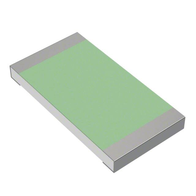
• SMD wraparound chip resistor
• Halogen-free according to IEC 61249-2-21 definition
Models
Available
Vishay Sfernice thick film resistor chips are specially
designed to meet very stringent specifications in terms
of reliability, stability < 0.25 % at Pn at +70 °C during
1000 h, homogeneity, reproducibility and quality.
They conform to specifications NFC 83-240 and
MIL-R-55342 D.
Evaluated to ESCC 4001/026 (see CHPHR datasheet).
Sputtered Thin Film terminations, with nickel barrier, are
very convenient for high operating conditions. They can
withstand thousands of very severe thermal shocks.
B (W/A), N (W/A), and F (one face) types are for solder reflow
assembly.
G (W/A) and W (one face) types are for wire bonding, gluing
and even high temperature solder reflow.
• Withstand moisture resistance test of AEC-Q200
• Material categorization: for definitions of compliance
please see www.vishay.com/doc?99912
Note
* This datasheet provides information about parts that are
RoHS-compliant and / or parts that are non RoHS-compliant. For
example, parts with lead (Pb) terminations are not RoHS-compliant.
Please see the information / tables in this datasheet for details
STANDARD ELECTRICAL SPECIFICATIONS
MODEL
SIZE
RATED
POWER
Pn
W
LIMITING
ELEMENT
VOLTAGE
V
MAX. OVERLOAD RESISTANCE
TEMPERATURE UNIT
TOLERANCE
VOLTAGE
RANGE (1)
COEFFICIENT WEIGHT
±%
V
± ppm/°C
mg
CHP0502
0.050
50
100
0.1 to 25M
0.5, 1, 2, 5
100, 200
HCHP0502 0502
CHP0505
0505
0.125
50
100
0.1 to 10M
0.5, 1, 2, 5
100, 200
HCHP0505
CHP0603
0603
0.125
50
100
0.1 to 25M
0.5, 1, 2, 5
100, 200
HCHP0603
CHP0805 (2)
0.200
150
300
0.1 to 25M
0.5, 1, 2, 5
100, 200
HCHP0805 0805
CHP1005
1005
0.250
150
300
0.1 to 50M
0.5, 1, 2, 5
100, 200
HCHP1005
CHP1206
1206
0.250
200
400
0.1 to 50M
0.5, 1, 2, 5
100, 200
HCHP1206
CHP1505
0.500
200
400
0.1 to 75M
0.5, 1, 2, 5
100, 200
HCHP1505 1505
CHP2010
2010
1.000 (3)
200
400
0.1 to 100M
0.5, 1, 2, 5
100, 200
HCHP2010
CHP1020
1020
1.000 (3)
200
400
0.1 to 10M
0.5, 1, 2, 5
100, 200
HCHP1020
CHP2208
0.750
200
400
0.1 to 100M
0.5, 1, 2, 5
100, 200
HCHP2208 2208
CHP2512
2512
2.000 (3)
250
500
0.1 to 100M
0.5, 1, 2, 5
100, 200
CHP2512
CHP1010
1010
0.500
200
400
0.1 to 25M
0.5, 1, 2, 5
100, 200
CHP1010
Notes
(1) Shall be read in conjunction with other tables
(2) Model CHP0805 being same size than case 0705 with same performances, only codification of CHP0805 remains
(3) With special assembly care
Revision: 24-Jan-18
1
3
2
4
5
8
8
26
25
21
42
12
Document Number: 52023
1
For technical questions, contact: sferthinfilm@vishay.com
THIS DOCUMENT IS SUBJECT TO CHANGE WITHOUT NOTICE. THE PRODUCTS DESCRIBED HEREIN AND THIS DOCUMENT
ARE SUBJECT TO SPECIFIC DISCLAIMERS, SET FORTH AT www.vishay.com/doc?91000
�CHP, HCHP
www.vishay.com
Vishay Sfernice
DIMENSIONS in millimeters
(B), (G), and (N)
(F) and (W)
D
C
D
C
B
B
E
E
A
A
A
B
C
D
E
± 0.152
± 0.127
± 0.127
± 0.127
± 0.127
0502
1.22
0.70
0.38
0.20
0.31
0505
1.22
1.25
0.38
0.20
0.31
0603
1.60
0.90
0.38
0.31
0.40
0805
1.85
1.25
0.38
0.31
0.50
1005
2.49
1.25
0.38
0.31
0.50
1010
2.49
2.64
0.38
0.31
0.50
1020
2.49
5.18
0.50
0.31
0.50
1206
3.00
1.73
0.38
0.40
0.50
1505
3.70
1.25
0.50
0.50
0.50
2010
5.03
2.64
0.50
0.50
0.50
2208
5.53
2.05
0.50
0.50
0.50
2512
6.30
3.30
0.50
0.50
0.50
CASE
SIZE
SUGGESTED LAND PATTERN (to IPC-7351A) in millimeters
Gmin.
Xmax.
Zmax.
CASE SIZE
Zmax.
Gmin.
Xmax.
0502
1.77
0.19
0.83
0505
1.77
0.19
1.38
0603
2.15
0.39
1.03
0805
2.70
0.44
1.38
1005
3.34
1.08
1.38
1010
3.34
1.08
2.77
1020
3.34
1.08
5.31
1206
3.85
1.59
1.85
1505
4.55
2.29
1.38
2010
5.88
3.62
2.77
2208
6.38
4.12
2.18
2512
7.15
4.89
3.43
Revision: 24-Jan-18
Document Number: 52023
2
For technical questions, contact: sferthinfilm@vishay.com
THIS DOCUMENT IS SUBJECT TO CHANGE WITHOUT NOTICE. THE PRODUCTS DESCRIBED HEREIN AND THIS DOCUMENT
ARE SUBJECT TO SPECIFIC DISCLAIMERS, SET FORTH AT www.vishay.com/doc?91000
�CHP, HCHP
www.vishay.com
Vishay Sfernice
Substrate
Alumina
Technology
Thick film (ruthenium oxide)
Protection
0.5 < R < 100 M: epoxy coating
R 0.5 : overglaze protection
(no epoxy coating)
Terminations
B (W/A):
SnPb over nickel barrier
for solder reflow
N (W/A):
SnAg over nickel barrier
for solder reflow
F (Flip Chip):
SnAg over nickel barrier
for solder reflow
W (one face) and G (W/A) type:
gold over nickel barrier
for other applications
Note
• Refer to Application Note “Guidelines for Vishay
Sfernice
Resistive
and
Inductive
Components”
(www.vishay.com/doc?52029) for recommended reflow profile.
Profile #3 applies
Rated Power (%)
POWER DERATING CURVE
MECHANICAL SPECIFICATIONS
100
80
60
40
20
0
0
20
Note
• For temperature up to 215 °C please consult Vishay Sfernice
BEST TOL. AND TCR VS. OHMIC VALUE
(1)
TIGHTEST
TOLERANCE
(%)
BEST
TCR
(ppm/°C)
10 < R < 5M
0.5 % (D)
100 (K)
5 < R < 10M
1 % (F)
100 (K)
1 < R < Rmax.
2 % (G)
200 (L)
0.1 < R < Rmax.
5 % (J)
200 (L)
OHMIC VALUE
RANGE in
Note
(1) Improved performance on request
CHIPS FOR HIGH FREQUENCY APPLICATIONS
The HF performance of flip chip and W/A types can be
improved on request.
Please ask for HCHP
100
120
140 155
PACKAGING
ESD packaging available: Waffle pack and plastic tape and
reel (low conductivity). Paper tapes available on request
(ESD only).
MOQ
CLIMATIC SPECIFICATIONS
-55 °C; +155 °C
60 70 80
Ambient Temperature in °C
SIZE
Operating temperature
range
40
0502
0505
0603
0805
1005
1206
1505
2010
1010
2208
1020
2512
NUMBER OF PIECES PER
WAFFLE
TAPE AND
PACK
MIN. MAX.
400
4000
100
TAPE
WIDTH
5000
8 mm
100
221
140
60
100
60
60
50
4000
100
2000
2500
4000
1000
2000
8 mm
8 mm
8 mm
8 mm
8 mm
PACKAGING RULES
Waffle Pack
Can be filled up to maximum quantity indicated in the table
here above, taking into account the minimum order quantity.
When quantity ordered exceeds maximum quantity of a
single waffle pack, the waffle packs are stacked up on the
top of each other and closed by one single cover.
To get “not stacked up” waffle pack in case of ordered
quantity > maximum number of pieces per package:
Please consult Vishay Sfernice for specific ordering
code
Tape and Reel
See Part Numbering information to get the quantity desired
by tape.
Revision: 24-Jan-18
Document Number: 52023
3
For technical questions, contact: sferthinfilm@vishay.com
THIS DOCUMENT IS SUBJECT TO CHANGE WITHOUT NOTICE. THE PRODUCTS DESCRIBED HEREIN AND THIS DOCUMENT
ARE SUBJECT TO SPECIFIC DISCLAIMERS, SET FORTH AT www.vishay.com/doc?91000
�CHP, HCHP
www.vishay.com
Vishay Sfernice
TYPICAL HF PERFORMANCE OF HCHP
2.0
2.0
1Ω
1.8
1.6
1.6
10 Ω
10 Ω
1.4
1.4
1.2
1.2
100 Ω
1.0
|Z|/R
|Z|/R
1Ω
1.8
200 Ω
0.8
100 Ω
1.0
200 Ω
1 kΩ
0.8
0.6
0.6
1 kΩ
0.4
1 MΩ
0.2
100 kΩ
10 kΩ
0.4
10 kΩ
1 MΩ
0.2
100 kΩ
0
0
1
10
100
1000
Size 0603 (W/A)
1
10 000
10
100
Size 0603 (Flip chip)
f (MHz)
1000
10 000
f (MHz)
POPULAR OPTIONS
For any option it is recommended to consult Vishay Sfernice for availability first.
Option: Enlarged terminations: 0063
For stringent and special power dissipation requirements, the thermal resistance between the resistive layer and the solder joint
can be reduced using enlarged terminations chip resistors which are soldered on large and thick copper pads acting as heat
sinks (see application note: 53048 Power Dissipation in High Precision Vishay Sfernice Chip Resistors and Arrays (P Thin Film,
PRA Arrays, CHP Thick Film) www.vishay.com/doc?53048.
Option to order: 0063 (applies to size 1206 / 1505 / 1020 / 2010 / 2512).
DIMENSIONS (Option 0063) in millimeters
Bottom view for mounting
Uncoated
ceramic
Enlarged
termination
C
E
D
B
A
A
B
C
D
E
± 0.152
± 0.127
± 0.127
± 0.127
± 0.127
1206
3.00
1.73
0.38
0.40
1.19
1505
3.70
1.25
0.50
0.50
1.54
2010
5.03
2.64
0.50
0.50
2.20
1020
2.49
5.18
0.50
0.31
0.93
2208
5.53
2.05
0.50
0.50
2.45
2512
6.30
3.30
0.50
0.50
2.84
CASE
SIZE
Revision: 24-Jan-18
Document Number: 52023
4
For technical questions, contact: sferthinfilm@vishay.com
THIS DOCUMENT IS SUBJECT TO CHANGE WITHOUT NOTICE. THE PRODUCTS DESCRIBED HEREIN AND THIS DOCUMENT
ARE SUBJECT TO SPECIFIC DISCLAIMERS, SET FORTH AT www.vishay.com/doc?91000
�CHP, HCHP
www.vishay.com
Vishay Sfernice
SUGGESTED LAND PATTERN (Option 0063)
Gmin.
Xmax.
Zmax.
DIMENSIONS (IN MILLIMETERS)
CASE SIZE
Zmax.
Gmin.
Xmax.
1206
3.85
0.50
1.86
1505
4.55
0.50
1.38
2010
5.88
0.50
2.77
1020
3.34
0.50
5.31
2208
6.38
0.50
2.18
2512
7.15
0.50
3.43
OPTION: MARKING
Option to order 0013:
Marking of ohmic value and tolerance:
Sizes: 0805 to 1005: 3 digits marking (according to EIA-96)
Sizes: 1206 to 2010: 4 digits marking (same codification than in the ordering procedure)
Tolerance indicated by a color dot.
Option to order 0014:
Marking of ohmic value:
Sizes 0805 to 1005: 3 digits marking (according to EIA-96)
Sizes 1206 to 2010: 4 digits marking (same codification than in the ordering procedure)
No standard marking available for smaller sizes.
A price adder will apply to the unit price of the parts for options 0013 and 0014.
PERFORMANCE
TESTS
Termination adhesion
Resistance to solder heat
Rapid temperature change
Climatic sequence
CONDITIONS
REQUIREMENTS
TYPICAL VALUES
AND DRIFTS
5N for 10 s
± (0.25 % + 0.05 )
< ± 0.1 %
Immersion 10 s
in Sn/Pb 60/40
at +260 °C
± (0.25 % + 0.05 )
< ± 0.1 %
± (0.25 % + 0.05 )
< ± 0.1 %
Phase A dry heat
Phase B damp heat
Phase C cold -55 °C
Phase D damp heat 5 cycles
± (1 % + 0.05 )
< ± 0.2 %
5 cycles
-55 °C
+155 °C
56 days
± (1 % + 0.05 )
< ± 0.2 %
Moisture resistance
AEC-Q200
85 °C / 85 % RH / Pn / 10
1000 h
5 % + 0.05
Max. < 3 % + 0.05
Short time overload
6.25 Pr
for 2 s
± (0.25 % + 0.05 )
< ± 0.1 %
1000 h at rated power
90’/30’ at +70 °C
1000 h
± (1 % + 0.05 )
Humidity (steady state)
Load life
Revision: 24-Jan-18
1000 h
< 0.25 %
2000 h
< 0.5 %
10 000 h


 工商网监
湘ICP备2023018690号
工商网监
湘ICP备2023018690号
