CPCL, CPCC, CPCP, CPCF
www.vishay.com
Vishay Dale
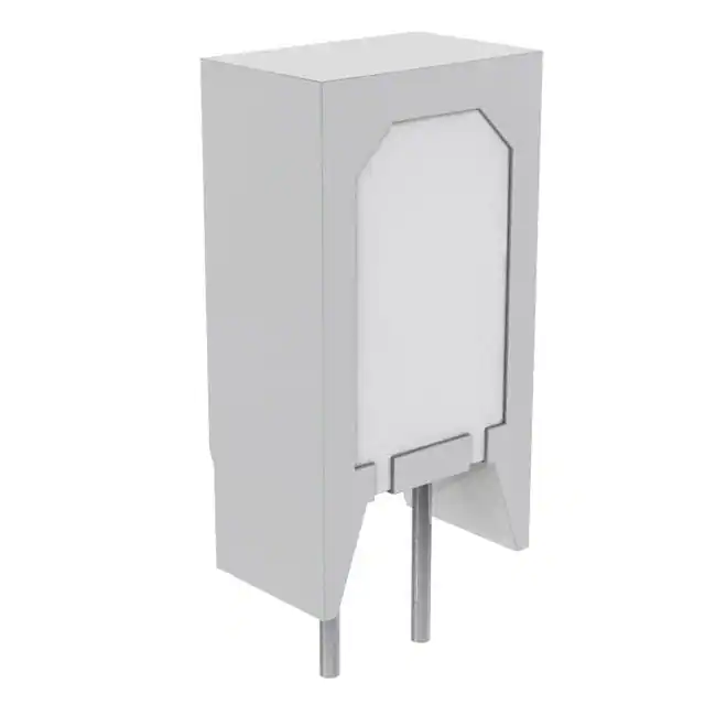
Wirewound / Metal Film Resistors,
Commercial Power, Vertical Mount
FEATURES
• Board space saving due to vertical design
• Meets or exceeds requirements of EIA standard
RS-344
• High power to size ratio
• Special inorganic potting compound and
ceramic case provide high thermal conductivity
in a fireproof package
• Material categorization:
for definitions of compliance please see
www.vishay.com/doc?99912
Available
Available
Available
Available
Note
* This datasheet provides information about parts that are RoHS-compliant and / or parts that are non RoHS-compliant. For example, parts
with lead (Pb) terminations are not RoHS-compliant. Please see the information / tables in this datasheet for details
STANDARD ELECTRICAL SPECIFICATIONS
GLOBAL
MODEL
HISTORICAL
MODEL
POWER RATING
P70 °C W
RESISTANCE RANGE
TOLERANCE
±%
WEIGHT (typical)
g
CPCL02
CPCL-2
2
0.01 to 0.10
5, 10
3.5
CPCC02
CPCC-2
2
0.1 to 500
5, 10
3.5
CPCP02
CPCP-2
2
0.1 to 4K
1, 5
3.5
CPCF02
CPCF-2
2
501 to 150K
1, 5, 10
3.5
CPCL03
CPCL-3
3
0.01 to 0.10
5, 10
5.5
CPCC03
CPCC-3
3
0.1 to 800
5, 10
5.5
CPCP03
CPCP-3
3
0.1 to 5K
1, 5
5.5
CPCF03
CPCF-3
3
801 to 150K
1, 5, 10
5.5
CPCL05
CPCL-5
5
0.01 to 0.10
5, 10
6.9
CPCC05
CPCC-5
5
0.1 to 800
5, 10
6.9
CPCP05
CPCP-5
5
0.1 to 5K
1, 5
6.9
CPCF05
CPCF-5
5
801 to 150K
1, 5, 10
6.9
14.3
CPCL10
CPCL-10
10
0.01 to 0.10
5, 10
CPCC10
CPCC-10
10
0.1 to 1.5K
5, 10
14.3
CPCP10
CPCP-10
10
0.1 to 8K
1, 5
14.3
Note
• Non-inductively wound types are available on the CPCP series signified by a 1 in the special character on part number such as
CPCP0510R00FB321. Maximum resistance value will be ½ of the standard CPCP
TECHNICAL SPECIFICATIONS
PARAMETER
Temperature Coefficient
UNIT
ppm/°C
CPCLxx
CPCCxx
± 100 = 0.05 to 0.1 ± 300 = 1.0 and above,
± 400 = 0.01 to 0.049 ± 600 = 0.1 to 0.99 ,
CPCPxx
CPCFxx
± 20 = 10 and above,
± 50 = 1.0 to 9.9
± 90 = 0.1 to 0.99
± 50 all values
Short Time Overload
-
5 x rated power for 5 s
Maximum Working Voltage
V
(P x R)1/2
Operating Temperature Range
°C
Terminal Strength
lb
10 minimum
VAC
1000
Dielectric Withstanding Voltage
Revision: 29-Sep-2020
-65 to +275
-65 to +225
Document Number: 30218
1
For technical questions, contact: ww2aresistors@vishay.com
THIS DOCUMENT IS SUBJECT TO CHANGE WITHOUT NOTICE. THE PRODUCTS DESCRIBED HEREIN AND THIS DOCUMENT
ARE SUBJECT TO SPECIFIC DISCLAIMERS, SET FORTH AT www.vishay.com/doc?91000
�CPCL, CPCC, CPCP, CPCF
www.vishay.com
Vishay Dale
GLOBAL PART NUMBER INFORMATION
Global Part Numbering Example: CPCC0515R00JB32
C
P
C
C
0
5
1
5
R
0
0
J
B
3
2
GLOBAL MODEL
VALUE
TOLERANCE
PACKAGING
SPECIAL
(See Standard Electrical
Specifications Global
Model column for
options)
R = decimal
K = thousand
R1500 = 0.15
1K500 = 1500
F = ± 1.0 %
H = ± 3.0 %
J = ± 5.0 %
K = ± 10.0 %
E32 = lead (Pb)-free two layer bulk
E01 = lead (Pb)-free skin pack
(Dash number)
(up to 3 digits)
From 1 to 999
as applicable
B32 = tin / lead two layer bulk
J01 = tin / lead skin pack
Historical Part Numbering Example: CPCC-5 15 5 % B32
CPCC-5
15
5%
B32
HISTORICAL MODEL
RESISTANCE VALUE
TOLERANCE CODE
PACKAGING
DIMENSIONS in inches [millimeters]
C
E
+ 0.078
0.177 - 0.039
1.98
[4.50 +- 0.991
]
B
A
D
DIMENSIONS in inches [millimeters]
A
± 0.031 [0.794]
B
± 0.031 [0.794]
C
+ 0.043 [1.09]
- 0.012 [0.305]
D
± 0.005 [0.127]
E
± 0.040 [1.02]
CPCL02, CPCC02
CPCP02, CPCF02
0.807 [20.50]
0.433 [11.00]
0.276 [7.01]
0.032 [0.813]
0.197 [5.00]
CPCL03, CPCC03
CPCP03, CPCF03
0.984 [24.99]
0.472 [11.99]
0.315 [8.00]
0.032 [0.813]
0.197 [5.00]
CPCL05, CPCC05
CPCP05, CPCF05
1.003 [25.48]
0.512 [13.00]
0.354 [8.99]
0.032 [0.813]
0.197 [5.00]
1.372 [34.85]
0.633 [16.08]
0.485 [12.32]
GLOBAL MODEL
CPCL10, CPCP10
CPCC10
0.040 [1.02]
0.036 [0.914]
0.290 [7.37]
MATERIAL SPECIFICATIONS
Part Marking: DALE, model, wattage, value, tolerance, date
code
CPCP: Element: copper-nickel alloy or nickel-chrome alloy,
depending on resistance value
CPCL: Element: self-supporting copper-nickel alloy or
nickel-chrome alloy, depending on resistance value
Body: steatite ceramic case with inorganic potting
compound
Terminals: tinned copper
Core: ceramic
Body: steatite ceramic case with inorganic potting
compound
End Caps: stainless steel
Terminals: tinned Copperweld®
CPCC: Element: copper-nickel alloy or nickel-chrome alloy,
depending on resistance value
Core: Woven fiberglass
Body: steatite ceramic case with inorganic potting
compound
End Caps: tin plated steel
Terminals: tinned copper
Revision: 29-Sep-2020
CPCF: Element: metal film - nickel-chrome alloy
Core: Alumina ceramic
Body: steatite ceramic case with inorganic potting
compound
End Caps: brass alloy
Terminals: solder-coated copper
Document Number: 30218
2
For technical questions, contact: ww2aresistors@vishay.com
THIS DOCUMENT IS SUBJECT TO CHANGE WITHOUT NOTICE. THE PRODUCTS DESCRIBED HEREIN AND THIS DOCUMENT
ARE SUBJECT TO SPECIFIC DISCLAIMERS, SET FORTH AT www.vishay.com/doc?91000
�CPCL, CPCC, CPCP, CPCF
www.vishay.com
Vishay Dale
RATED POWER IN %
DERATING
120
100
CPCL
CPCC
CPCP
80
60
40
CPCF
20
0
- 65 - 25
25
75
70
125
175
225
275
AMBIENT TEMPERATURE IN °C
PERFORMANCE
CONDITIONS OF TEST
CPCP TEST LIMITS
CPCC, CPCL, CPCF
TEST LIMITS
Thermal Shock
-55 °C to +275 °C (+225 °C for CPCF),
5 cycles, 30 min dwell time
± (2.0 % + 0.05 ) R
± (5.0 % + 0.05 ) R
Short Time Overload
5 x rated power for 5 s
± (2.0 % + 0.05 ) R
± (4.0 % + 0.05 ) R
Dielectric Withstanding Voltage
1000 VRMS for 1 min
± (0.1 % + 0.05 ) R
± (2.0 % + 0.05 ) R
Low Temperature Storage
-65 °C, full rated working voltage for 45 min
± (2.0 % + 0.05 ) R
± (3.0 % + 0.05 ) R
Bias Humidity
75 °C, 90 % to 100 % RH, 240 h
± (2.0 % + 0.05 ) R
± (5.0 % + 0.05 ) R
Load Life
1000 h at rated power, + 40 °C, 1.5 h “ON”, 0.5 h “OFF”
± (5.0 % + 0.05 ) R
± (5.0 % + 0.05 ) R
Terminal Strength
5 s to 10 s 10 pound pull test
± (1.0 % + 0.05 ) R
± (1.0 % + 0.05 ) R
Resistance to Solder Heat
Terminal immersed 3.5 s in molten solder up to body
± (1.0 % + 0.05 ) R
± (4.0 % + 0.05 ) R
TEST
Revision: 29-Sep-2020
Document Number: 30218
3
For technical questions, contact: ww2aresistors@vishay.com
THIS DOCUMENT IS SUBJECT TO CHANGE WITHOUT NOTICE. THE PRODUCTS DESCRIBED HEREIN AND THIS DOCUMENT
ARE SUBJECT TO SPECIFIC DISCLAIMERS, SET FORTH AT www.vishay.com/doc?91000
�Legal Disclaimer Notice
www.vishay.com
Vishay
Disclaimer
ALL PRODUCT, PRODUCT SPECIFICATIONS AND DATA ARE SUBJECT TO CHANGE WITHOUT NOTICE TO IMPROVE
RELIABILITY, FUNCTION OR DESIGN OR OTHERWISE.
Vishay Intertechnology, Inc., its affiliates, agents, and employees, and all persons acting on its or their behalf (collectively,
“Vishay”), disclaim any and all liability for any errors, inaccuracies or incompleteness contained in any datasheet or in any other
disclosure relating to any product.
Vishay makes no warranty, representation or guarantee regarding the suitability of the products for any particular purpose or
the continuing production of any product. To the maximum extent permitted by applicable law, Vishay disclaims (i) any and all
liability arising out of the application or use of any product, (ii) any and all liability, including without limitation special,
consequential or incidental damages, and (iii) any and all implied warranties, including warranties of fitness for particular
purpose, non-infringement and merchantability.
Statements regarding the suitability of products for certain types of applications are based on Vishay’s knowledge of
typical requirements that are often placed on Vishay products in generic applications. Such statements are not binding
statements about the suitability of products for a particular application. It is the customer’s responsibility to validate that a
particular product with the properties described in the product specification is suitable for use in a particular application.
Parameters provided in datasheets and / or specifications may vary in different applications and performance may vary over
time. All operating parameters, including typical parameters, must be validated for each customer application by the customer’s
technical experts. Product specifications do not expand or otherwise modify Vishay’s terms and conditions of purchase,
including but not limited to the warranty expressed therein.
Except as expressly indicated in writing, Vishay products are not designed for use in medical, life-saving, or life-sustaining
applications or for any other application in which the failure of the Vishay product could result in personal injury or death.
Customers using or selling Vishay products not expressly indicated for use in such applications do so at their own risk.
Please contact authorized Vishay personnel to obtain written terms and conditions regarding products designed for
such applications.
No license, express or implied, by estoppel or otherwise, to any intellectual property rights is granted by this document
or by any conduct of Vishay. Product names and markings noted herein may be trademarks of their respective owners.
© 2021 VISHAY INTERTECHNOLOGY, INC. ALL RIGHTS RESERVED
Revision: 01-Jan-2021
1
Document Number: 91000
�


 工商网监
湘ICP备2023018690号
工商网监
湘ICP备2023018690号
