CRHP
www.vishay.com
Vishay Techno
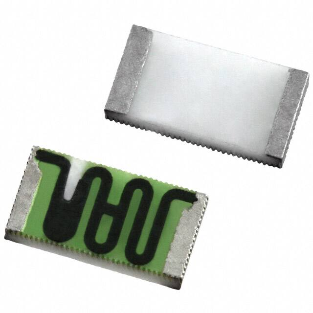
Thick Film Chip Resistors, High Voltage
FEATURES
•
•
•
•
•
•
•
•
•
•
•
High voltage up to 3000 V
Available
Outstanding stability < 0.5 %
Flow solderable
Available
Automatic placement capability
Tape and reel packaging available
Termination style:
3-sided wraparound termination
Internationally standardized sizes
Termination material: solder-coated nickel barrier or
solder coated non-magnetic terminations standard
Multiple styles, termination materials and configurations,
allow wide design flexibility
Epoxy bondable or wire bondable non-magnetic
terminations available
Material categorization: for definitions of compliance
please see www.vishay.com/doc?99912
Note
* This datasheet provides information about parts that are RoHS-compliant and / or parts that are non RoHS-compliant. For example, parts
with lead (Pb) terminations are not RoHS-compliant. Please see the information / tables in this datasheet for details
STANDARD ELECTRICAL SPECIFICATIONS
GLOBAL
MODEL
CRHP1206
CRHP1210
CRHP2010
CRHP2510
CRHP2512
CASE SIZE
POWER RATING
P70 °C
W
MAXIMUM
WORKING
VOLTAGE (1)
V
1206
0.50
1675
1210
2010
2510
2512
0.70
1.0
1.2
1.5
1870
2000
2500
3000
RESISTANCE
RANGE (2)
Ω
TOLERANCE (3)
±%
2M to 100M
0.5
2M to 1G
1, 2, 5, 10, 20
1.1G to 8G
2, 5, 10, 20
4M to 100M
0.5
4M to 1G
1, 2, 5, 10, 20
1.1G to 10G
2, 5, 10, 20
6M to 100M
0.5
6M to 1G
1, 2, 5, 10, 20
1.1G to 10G
2, 5, 10, 20
11G to 35G
5, 10, 20
10M to 100M
0.5
10M to 1G
1, 2, 5, 10, 20
1.1G to 10G
2, 5, 10, 20
11G to 40G
5, 10, 20
10M to 100M
0.5
10M to 1G
1, 2, 5, 10, 20
1.1G to 10G
2, 5, 10, 20
11G to 50G
5, 10, 20
TEMPERATURE
COEFFICIENT (4)
(-55 °C to +155 °C)
± ppm/°C
100
100
100
100
100
Notes
• For non-standard sizes, lower values or higher power rating requirement, contact factory
(1) Continuous working voltage shall be P x R or maximum working voltage, whichever is less
(2) Resistance values below 1 GΩ are calibrated at 100 V , and values of 1 GΩ and above are calibrated at 1000 V . Calibration at other
DC
DC
voltages available upon request
(3) Contact factory for tighter tolerances
(4) Reference only: not for all values specified. Consult factory for your size and value
Revision: 19-May-2021
Document Number: 68045
1
For technical questions, contact: te1resistors@vishay.com
THIS DOCUMENT IS SUBJECT TO CHANGE WITHOUT NOTICE. THE PRODUCTS DESCRIBED HEREIN AND THIS DOCUMENT
ARE SUBJECT TO SPECIFIC DISCLAIMERS, SET FORTH AT www.vishay.com/doc?91000
�CRHP
www.vishay.com
Vishay Techno
GLOBAL PART NUMBER INFORMATION
New Global Part Numbering: CRHP1206AF100MFKFB (preferred part number format)
GLOBAL
MODEL
CRHP
R
SIZE
1206
1210
2010
2510
2512
H
P
1
2
0
6
A
TERMINAL
STYLE
TERMINAL
MATERIAL
RESISTANCE
VALUE
A = 3-sided
F = nickel barrier
G = non-magnetic
M = MΩ
G = GΩ
4M70 = 4.7 MΩ
10M0 = 10 MΩ
1G00 = 1 GΩ
F
Substrate
K
SOLDER
TERMINATION
K = 100 ppm
L = 150 ppm
N = 200 ppm
R = 250 ppm
M = 300 ppm
W = 350 ppm
P = 500 ppm
E = Sn100
F = Sn95/Ag5, HSD
T = Sn90/Pb10
F
B
PACKAGING
B = bulk
(250 pcs max.)
F = T/R
(full reel)
1 = T/R
(1000 pcs)
5 = T/R
(500 pcs)
T = T/R
(250 pcs min.)
W = waffle tray
DERATING CURVE
Axis Title
10000
120
100
96 % alumina
Solder finish
Pure tin or tin/lead solder alloys standard.
Tin/silver solder alloy available.
1000
80
60
100
40
20
ENVIRONMENTAL SPECIFICATIONS
10
0
-55 °C to +155 °C
-55
-25
0
25
50 70
100 125
155 175
Ambient Temperature (°C)
Less than 0.5 % change when tested
at full rated power
Short time overload
F
Glass
Solder-coated nickel barrier or solder
coated non-magnetic terminations
standard
Life
M
D = ± 0.5 %
F=±1%
G=±2%
J=±5%
K = ± 10 %
M = ± 20 %
Ruthenium oxide
Termination
Operating
temperature
0
TCR
2nd line
Rated Power (%)
Encapsulation
0
TOLERANCE
MECHANICAL SPECIFICATIONS
Resistive element
1
1st line
2nd line
C
Note
• Reference only: not for all values specified. Consult factory for
your size and value
Less than 0.5 % ΔR
VOLTAGE COEFFICIENT OF RESISTANCE CHART
SIZE
VALUE (Ω)
VCR (ppm/V)
FURTHER INSTRUCTIONS
CRHP1206
2M to 199M
25
Values over 200M, consult factory
CRHP1210
4M to 200M
25
Values over 200M, consult factory
6M to 99M
15
100M to 1G
20
10M to 99M
10
100M to 1G
15
10M to 999M
10
1G to 5G
25
CRHP2010
CRHP2510
CRHP2512
Revision: 19-May-2021
Values over 1G, consult factory
Values over 1G, consult factory
Values over 5G, consult factory
Document Number: 68045
2
For technical questions, contact: te1resistors@vishay.com
THIS DOCUMENT IS SUBJECT TO CHANGE WITHOUT NOTICE. THE PRODUCTS DESCRIBED HEREIN AND THIS DOCUMENT
ARE SUBJECT TO SPECIFIC DISCLAIMERS, SET FORTH AT www.vishay.com/doc?91000
�CRHP
www.vishay.com
Vishay Techno
DIMENSIONS in inches (millimeters)
Termination Style A
(3-sided wraparound)
W
L
T
0.025 [0.635]
Max.
LENGTH (L)
± 0.006 (0.152)
WIDTH (W)
± 0.006 (0.152)
THICKNESS (T)
± 0.002 (0.051)
CRHP1206
0.125
0.063
0.025
CRHP1210
0.125
0.100
0.025
CRHP2010
0.200
0.100
0.025
CRHP2510
0.250
0.100
0.025
CRHP2512
0.250
0.126
0.025
MODEL
TYPE
TERMINATION
MATERIAL
TERMINATION
STYLE
TERMINATION STYLE /
MATERIAL CODE
SOLDER TERMINATION
CODE
Nickel barrier
3-sided (wraparound)
AF
E or T (standard);
F (optional) (1)
Non-magnetic
3-sided (wraparound)
AG
E or T (standard);
F (optional) (1)
Solderable
Note
(1) Standard solder plating for the nickel barrier and non-magnetic parts is solder terminations E or T.
Hot solder dipped termination F is also available
PERFORMANCE
TEST
CONDITIONS OF TEST
TEST RESULTS
(TYPICAL TEST LOTS)
Life
MIL-STD-202, method 108, 1000 h rated power at +70 °C
≤ ± 0.5 %
High temperature exposure
MIL-STD-202, method 108
≤ ± 0.2 %
Low temperature operation
MIL-PRF-55342, paragraph 4.8.5
≤ ± 0.05 %
Resistance to bonding exposure
MIL-STD-202, methods 210
≤ ± 0.1 %
Moisture resistance
MIL-PRF-55342, paragraph 4.8.9
≤ ± 0.06 %
Solder mounting integrity
MIL-PRF-55342, paragraph 4.8.13, 2 kg for 30 s
Solderability
MIL-STD-202, method 208
Revision: 19-May-2021
No evidence of mechanical damage
95 % coverage
Document Number: 68045
3
For technical questions, contact: te1resistors@vishay.com
THIS DOCUMENT IS SUBJECT TO CHANGE WITHOUT NOTICE. THE PRODUCTS DESCRIBED HEREIN AND THIS DOCUMENT
ARE SUBJECT TO SPECIFIC DISCLAIMERS, SET FORTH AT www.vishay.com/doc?91000
�Legal Disclaimer Notice
www.vishay.com
Vishay
Disclaimer
ALL PRODUCT, PRODUCT SPECIFICATIONS AND DATA ARE SUBJECT TO CHANGE WITHOUT NOTICE TO IMPROVE
RELIABILITY, FUNCTION OR DESIGN OR OTHERWISE.
Vishay Intertechnology, Inc., its affiliates, agents, and employees, and all persons acting on its or their behalf (collectively,
“Vishay”), disclaim any and all liability for any errors, inaccuracies or incompleteness contained in any datasheet or in any other
disclosure relating to any product.
Vishay makes no warranty, representation or guarantee regarding the suitability of the products for any particular purpose or
the continuing production of any product. To the maximum extent permitted by applicable law, Vishay disclaims (i) any and all
liability arising out of the application or use of any product, (ii) any and all liability, including without limitation special,
consequential or incidental damages, and (iii) any and all implied warranties, including warranties of fitness for particular
purpose, non-infringement and merchantability.
Statements regarding the suitability of products for certain types of applications are based on Vishay's knowledge of typical
requirements that are often placed on Vishay products in generic applications. Such statements are not binding statements
about the suitability of products for a particular application. It is the customer's responsibility to validate that a particular product
with the properties described in the product specification is suitable for use in a particular application. Parameters provided in
datasheets and / or specifications may vary in different applications and performance may vary over time. All operating
parameters, including typical parameters, must be validated for each customer application by the customer's technical experts.
Product specifications do not expand or otherwise modify Vishay's terms and conditions of purchase, including but not limited
to the warranty expressed therein.
Hyperlinks included in this datasheet may direct users to third-party websites. These links are provided as a convenience and
for informational purposes only. Inclusion of these hyperlinks does not constitute an endorsement or an approval by Vishay of
any of the products, services or opinions of the corporation, organization or individual associated with the third-party website.
Vishay disclaims any and all liability and bears no responsibility for the accuracy, legality or content of the third-party website
or for that of subsequent links.
Except as expressly indicated in writing, Vishay products are not designed for use in medical, life-saving, or life-sustaining
applications or for any other application in which the failure of the Vishay product could result in personal injury or death.
Customers using or selling Vishay products not expressly indicated for use in such applications do so at their own risk. Please
contact authorized Vishay personnel to obtain written terms and conditions regarding products designed for such applications.
No license, express or implied, by estoppel or otherwise, to any intellectual property rights is granted by this document or by
any conduct of Vishay. Product names and markings noted herein may be trademarks of their respective owners.
© 2021 VISHAY INTERTECHNOLOGY, INC. ALL RIGHTS RESERVED
Revision: 09-Jul-2021
1
Document Number: 91000
�


 工商网监
湘ICP备2023018690号
工商网监
湘ICP备2023018690号
