D Series
Vishay BCcomponents
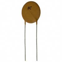
Ceramic Disc Capacitors
Class 1 and 2, 100 VDC, General Purpose
FEATURES
D
D
• Low losses
• High stability
• High capacitance in small size
Tangent
line
Tangent
line
SH
DR
• Kinked (preferred) or straight leads
• Compliant to RoHS directive 2002/95/EC
APPLICATIONS
• Bypassing
• Coupling
F
• Resonant circuit
F
Capacitors with 5 mm (0.20") and 2.5 mm (0.10") lead spacing
DESIGN
QUICK REFERENCE DATA
The capacitors consist of a ceramic disc both sides of which
are silver-plated. Connection leads are made of tinned
copper having a diameter of 0.6 mm.
The capacitors have inward kinked leads with a spacing of
5 mm (0.200") and straight leads with 2.5 mm (0.100"), lead
length from 4 mm to 30 mm.
DESCRIPTION
CLASS 1
(NP0, SL0)
CLASS 2
(YP5, Z50, Y5V, Z5V)
Voltage (VDC)
100
Min. Capacitance (pF)
1.0
150
Max. Capacitance (pF)
100
47 000
Mounting
Through hole
CAPACITANCE RANGE
1.0 pF to 100 pF; Class 1, at 1 MHz, 1.2 VRMS
MARKING
150 pF to 47 000 pF; Class 2, at 1 kHz, 1 VRMS ± 0.2 VRMS
Marking indicates capacitance value and tolerance in
accordance with “EIA 198”.
1 kHz, 1 VRMS ± 0.2 VRMS for capacitance values higher than
1000 pF
OPERATING TEMPERATURE RANGE
RATED DC VOLTAGE
Class 1, - 55 °C to + 125 °C
Class 2, - 30 °C to + 85 °C
100 V
TEMPERATURE COEFFICIENTS
Class 1, NP0; SL0
Class 2, Y5P; Z5U; Y5V; Z5V
SECTIONAL SPECIFICATIONS
Class 1, IEC 60 384-8,
Class 2, IEC 60 384-9,
EIA 198
CLIMATIC CATEGORY
Class 1, 55/125/21
Class 2, 10/85/21 and 30/85/21
DIELECTRIC STRENGTH
250 % of rated voltage
INSULATION RESISTANCE AT 100 VDC
≥ 10 000 MΩ
TOLERANCE ON CAPACITANCE
± 0.25 pF; ± 0.5 pF; ± 5 % ; ± 10 %; ± 20 %; + 80/- 20 %
DISSIPATION FACTOR
Class 1, C ≤ 30 pF; ≤ 2 x (10/C + 0.7) x 10-4 maximum
Class 1, C > 30 pF; ≤ 0.2 %
Class 2, ≤ 3.0 %
Note
The capacitors meet the essential requirements of “EIA 198”. Unless stated otherwise all electrical values apply at an ambient temperature of
25 °C ± 3 °C, at normal atmospheric conditions.
www.vishay.com
28
For technical questions, contact: CDC@vishay.com
Document Number: 28511
Revision: 07-Jan-10
�D Series
Ceramic Disc Capacitors
Class 1 and 2, 100 VDC, General Purpose
Vishay BCcomponents
ORDERING INFORMATION, CLASS 1, 100 VDC, KINKED AND STRAIGHT
C
(pF)
TOL.
(%)
DMAX.
(mm)
CLEAR TEXT CODE
LEAD SPACING
F
(mm)
SH/DRMAX. (1)
(mm)
5.0
4.0
D109C20C0KH6.J5R
2.5
1.5
D109C20C0KH6.L2R
5.0
4.0
D159C20C0KH6.J5R
2.5
1.5
D159C20C0KH6.L2R
5.0
4.0
D229C20C0JH6.J5R
2.5
1.5
D229C20C0JH6.L2R
5.0
4.0
D339C20C0JH6.J5R
2.5
1.5
D339C20C0JH6.L2R
5.0
4.0
D479C20C0HH6.J5R
2.5
1.5
D479C20C0HH6.L2R
13TH DIGIT:
T = REEL; U = AMMO; 3 = BULK
CLASS 1 NP0
1.0
1.5
2.2
± 0.25 pF
3.3
4.7
6.8
± 0.5 pF
10
5.0
12
15
18
22
±5
27
33
39
6.5
47
5.0
4.0
D689D20C0HH6.J5R
2.5
1.5
D689D20C0HH6.L2R
5.0
4.0
D100J20C0GH6.J5R
2.5
1.5
D100J20C0GH6.L2R
5.0
4.0
D120J20C0GH6.J5R
2.5
1.5
D120J20C0GH6.L2R
5.0
4.0
D150J20C0GH6.J5R
2.5
1.5
D150J20C0GH6.L2R
5.0
4.0
D180J20C0GH6.J5R
2.5
1.5
D180J20C0GH6.L2R
5.0
4.0
D220J20C0GH6.J5R
2.5
1.5
D220J20C0GH6.L2R
5.0
4.0
D270J20C0GH6.J5R
2.5
1.5
D270J20C0GH6.L2R
5.0
4.0
D330J20C0GH6.J5R
2.5
1.5
D330J20C0GH6.L2R
5.0
4.0
D390J25C0GH6.J5R
2.5
1.5
D390J25C0GH6.L2R
5.0
4.0
D470J25C0GH6.J5R
2.5
1.5
D470J25C0GH6.L2R
CLASS 1 SL0
56
68
±5
5.0
82
100
5.0
4.0
D560J20SL0H6.J5R
2.5
1.5
D560J20SL0H6.L2R
5.0
4.0
D680J20SL0H6.J5R
2.5
1.5
D680J20SL0H6.L2R
5.0
4.0
D820J20SL0H6.J5R
2.5
1.5
D820J20SL0H6.L2R
5.0
4.0
D101J20SL0H6.J5R
2.5
1.5
D101J20SL0H6.L2R
Notes
(1) SH = seated height; DR = run down
• Maximum thickness 4.0 mm
• Lead style codes refer to lead cofigurations
Document Number: 28511
Revision: 07-Jan-10
For technical questions, contact: CDC@vishay.com
www.vishay.com
29
�D Series
Vishay BCcomponents
Ceramic Disc Capacitors
Class 1 and 2, 100 VDC, General Purpose
ORDERING INFORMATION, CLASS 2, 100 VDC, KINKED AND STRAIGHT
C
(pF)
TOL.
(%)
DMAX.
(mm)
CLEAR TEXT CODE
LEAD SPACING
F
(mm)
SH/DRMAX. (1)
(mm)
5.0
2.5
5.0
2.5
5.0
2.5
5.0
2.5
5.0
2.5
5.0
2.5
5.0
2.5
5.0
2.5
5.0
2.5
5.0
2.5
5.0
2.5
5.0
2.5
5.0
2.5
5.0
2.5
4.0
1.5
4.0
1.5
4.0
1.5
4.0
1.5
4.0
1.5
4.0
1.5
4.0
1.5
4.0
1.5
4.0
1.5
4.0
1.5
4.0
1.5
4.0
1.5
4.0
1.5
4.0
1.5
D151K20Y5PH6.J5R
D151K20Y5PH6.L2R
D181K20Y5PH6.J5R
D181K20Y5PH6.L2R
D221K20Y5PH6.J5R
D221K20Y5PH6.L2R
D331K20Y5PH6.J5R
D331K20Y5PH6.L2R
D471K20Y5PH6.J5R
D471K20Y5PH6.L2R
D681K20Y5PH6.J5R
D681K20Y5PH6.L2R
D102K20Y5PH6.J5R
D102K20Y5PH6.L2R
D152K25Y5PH6.J5R
D152K25Y5PH6.L2R
D182K25Y5PH6.J5R
D182K25Y5PH6.L2R
D222K25Y5PH6.J5R
D222K25Y5PH6.L2R
D332K29Y5PH6.J5R
D332K29Y5PH6.L2R
D472K33Y5PH6.J5R
D472K33Y5PH6.L2R
D682K39Y5PH6.J5R
D682K39Y5PH6.L2R
D103K43Y5PH6.J5R
D103K43Y5PH6.L2R
5.0
2.5
5.0
2.5
5.0
2.5
5.0
2.5
5.0
2.5
5.0
2.5
5.0
2.5
5.0
2.5
5.0
2.5
4.0
1.5
4.0
1.5
4.0
1.5
4.0
1.5
4.0
1.5
4.0
1.5
4.0
1.5
4.0
1.5
4.0
1.5
D102M20Z5UH6.J5R
D102M20Z5UH6.L2R
D152M20Z5UH6.J5R
D152M20Z5UH6.L2R
D222M20Z5UH6.J5R
D222M20Z5UH6.L2R
D332M20Z5UH6.J5R
D332M20Z5UH6.L2R
D472M25Z5UH6.J5R
D472M25Z5UH6.L2R
D682M25Z5UH6.J5R
D682M25Z5UH6.L2R
D103M29Z5UH6.J5R
D103M29Z5UH6.L2R
D153M33Z5UH6.J5R
D153M33Z5UH6.L2R
D223M39Z5UH6.J5R
D223M39Z5UH6.L2R
13TH DIGIT:
T = REEL; U = AMMO; 3 = BULK
CLASS 2 Y5P
150
180
220
330
5.0
470
680
1000
±10
1500
1800
6.5
2200
3300
7.5
4700
8.5
6800
10.0
10000
11.0
CLASS 2 Z5U
1000
1500
5.0
2200
3300
4700
± 20
6.5
6800
10 000
7.5
15 000
8.5
22 000
10.0
Note
(1) SH = seated height; DR = run down
• Maximum thickness 4.0 mm
• Lead style codes refer to lead cofiguration
www.vishay.com
30
For technical questions, contact: CDC@vishay.com
Document Number: 28511
Revision: 07-Jan-10
�D Series
Ceramic Disc Capacitors
Class 1 and 2, 100 VDC, General Purpose
Vishay BCcomponents
ORDERING INFORMATION, CLASS 2, 100 VDC, KINKED AND STRAIGHT
C
(pF)
TOL.
(%)
DMAX.
(mm)
CLEAR TEXT CODE
LEAD SPACING
F
(mm)
SH/DRMAX. (1)
(mm)
5.0
2.5
5.0
2.5
5.0
2.5
5.0
2.5
5.0
2.5
5.0
2.5
5.0
2.5
5.0
2.5
5.0
2.5
4.0
1.5
4.0
1.5
4.0
1.5
4.0
1.5
4.0
1.5
4.0
1.5
4.0
1.5
4.0
1.5
4.0
1.5
D102Z20Y5VH6.J5R
D102Z20Y5VH6.L2R
D152Z20Y5VH6.J5R
D152Z20Y5VH6.L2R
D222Z20Y5VH6.J5R
D222Z20Y5VH6.L2R
D332Z20Y5VH6.J5R
D332Z20Y5VH6.L2R
D472Z25Y5VH6.J5R
D472Z25Y5VH6.L2R
D682Z25Y5VH6.J5R
D682Z25Y5VH6.L2R
D103Z29Y5VH6.J5R
D103Z29Y5VH6.L2R
D153Z33Y5VH6.J5R
D153Z33Y5VH6.L2R
D223Z39Y5VH6.J5R
D223Z39Y5VH6.L2R
5.0
2.5
5.0
2.5
5.0
2.5
4.0
1.5
4.0
1.5
4.0
1.5
D472Z20Z5VH6.J5R
D472Z20Z5VH6.L2R
D103Z25Z5VH6.J5R
D103Z25Z5VH6.L2R
D223Z33Z5VH6.J5R
D223Z33Z5VH6.L2R
5.0
4.0
D473Z43Z5VH6.J5R
2.5
1.5
D473Z43Z5VH6.L2R
13TH DIGIT:
T = REEL; U = AMMO; 3 = BULK
CLASS 2 Y5V
1000
1500
5.0
2200
3300
4700
+ 80/- 20
6.5
6800
10 000
7.5
15 000
8.5
22 000
10.0
CLASS 2 Z5V
4700
5.0
10 000
6.5
+ 80/- 20
22 000
8.5
47 000
11.0
Note
(1) SH = seated height; DR = run down
• Maximum thickness 4.0 mm
• Lead style codes refer to lead cofiguration
PACKAGING
DMAX.
(mm)
SIZE CODE
5.0 (0.20")
20
6.5 (0.25")
25
7.5 (0.29")
29
8.5 (0.33")
33
10.0 (0.39")
39
11.0 (0.43")
43
PACKAGING QUANTITIES
BULK
REEL
AMMO
1000
2500
2000
Note
• The capacitors are supplied in bulk packaging (cardboard boxes), in tape on reel or in ammopack
Document Number: 28511
Revision: 07-Jan-10
For technical questions, contact: CDC@vishay.com
www.vishay.com
31
�D Series
Vishay BCcomponents
Ceramic Disc Capacitors
Class 1 and 2, 100 VDC, General Purpose
P2
D
Δh
P
ΔP
Δh
ΔP
H1
W2
H0
W1
W0 W
A
e
P1
Ød
Direction of unreeling
F
P0
D0
t1
detail A
Kinked capacitors on tape, lead spacing 5.0 mm (0.2")
DIMENSION OF TAPE
DIMENSIONS (mm)
SYMBOL
PARAMETER
D
Body diameter
11.0 maximum
-
d
Lead diameter
0.6
± 0.05
P
Pitch between capacitors
12.7
± 1.0
Feed-hole pitch
12.7
± 0.3 (1)
P0 (1)
ΔP
NOMINAL
TOLERANCE
Plane deviation
1.0 maximum
-
P1 (2)
Feed-hole center to lead center
3.85
± 0.7; (2)
P2 (2)
Feed-hole center to component center
6.35
± 1.3; (2)
F
Lead spacing
5.0
0.6
- 0.4
Δh
Component alignment
0
± 1.0
W
Tape width
18.0
1.0
- 0.5
W0
Hold-down tape width
5.0 minimum
0.75
- 0.5
W1
Hole position
9.0
W2
Hold-down tape margin
3.0 maximum
-
H0
Height to seating plane
16.0
± 0.5
H1
Maximum component height
32.0
-
e
Lead end protrusion
1.0 maximum
-
L
Maximum length of snipped lead
11.0
-
D0
Feed-hole diameter
4.0
± 0.2
t
Total tape thickness
0.9 maximum
-
t1
Maximum thickness of tape and wires
1.5 maximum
-
Notes
(1) Cumulative pitch error: ± ≤ 1 mm/20 pitches
(2) Obliquity maximum 3°
www.vishay.com
32
For technical questions, contact: CDC@vishay.com
Document Number: 28511
Revision: 07-Jan-10
�D Series
Ceramic Disc Capacitors
Class 1 and 2, 100 VDC, General Purpose
Vishay BCcomponents
REEL AND TAPE DATA in millimeters
51 max.
355.6 ± 2.0
28 ± 1.5
8.0
45 max.
Reel with capacitors on tape
290
335
50
Ammopack with capacitors on tape
Document Number: 28511
Revision: 07-Jan-10
For technical questions, contact: CDC@vishay.com
www.vishay.com
33
�Legal Disclaimer Notice
Vishay
Disclaimer
All product specifications and data are subject to change without notice.
Vishay Intertechnology, Inc., its affiliates, agents, and employees, and all persons acting on its or their behalf
(collectively, “Vishay”), disclaim any and all liability for any errors, inaccuracies or incompleteness contained herein
or in any other disclosure relating to any product.
Vishay disclaims any and all liability arising out of the use or application of any product described herein or of any
information provided herein to the maximum extent permitted by law. The product specifications do not expand or
otherwise modify Vishay’s terms and conditions of purchase, including but not limited to the warranty expressed
therein, which apply to these products.
No license, express or implied, by estoppel or otherwise, to any intellectual property rights is granted by this
document or by any conduct of Vishay.
The products shown herein are not designed for use in medical, life-saving, or life-sustaining applications unless
otherwise expressly indicated. Customers using or selling Vishay products not expressly indicated for use in such
applications do so entirely at their own risk and agree to fully indemnify Vishay for any damages arising or resulting
from such use or sale. Please contact authorized Vishay personnel to obtain written terms and conditions regarding
products designed for such applications.
Product names and markings noted herein may be trademarks of their respective owners.
Document Number: 91000
Revision: 18-Jul-08
www.vishay.com
1
�