HV 500 V
Vishay BCcomponents
Ceramic Disc Capacitors
Class 1 and 2, 500 V (DC) General Purpose
FEATURES
�
• Low losses
• High stability
• High capacitance in small size
���� ��
��
• Kinked (preferred) or straight leads.
��
APPLICATIONS
• Bypassing
• Coupling
• Resonant circuit.
�
Capacitors with 5 mm (0.20") lead spacing.
DESIGN
The capacitors consist of a ceramic disc both sides of which
are silver-plated. Connection leads are made of tinned
copper having a diameter of 0.6 mm.
�
The capacitors have inward kinked leads with a spacing of
5 mm (0.200") or 7.5 mm (0.300”) and a lead length from
4 to 30 mm. Encapsulation is made of phenolic resin.
���� ��
��
��
CAPACITANCE RANGE:
Class 1, at 1 MHz, 1.2 V (RMS); 10 to 82 pF
1 kHz, 1 ± 0.2 V (RMS) for capacitance values higher than 1000 pF.
Class 2, at 1 kHz, 1 ± 0.2 V (RMS); 100 to 22000 pF
�
RATED DC VOLTAGE:
500 V
Capacitors with 7.5 mm (0.30") lead spacing.
DIELECTRIC STRENGTH:
250 % of rated voltage
SECTIONAL SPECIFICATIONS:
Class 1 IEC 60 384-8,
INSULATION RESISTANCE AT 500V (DC):
≥10000 MΩ
Class 2 IEC 60 384-9,
EIA 198
TOLERANCE ON CAPACITANCE:
CLIMATIC CATEGORY:
± 5 %; ± 10 %; ± 20 %; + 80 /- 20 %
Class 1 55/125/21
DISSIPATION FACTOR:
Class 2 10/85/21 and 30/85/21
Class 1, C ≤ 30 pF; ≤ 20 x (10/C + 0.7) x 10-4 maximum
OPERATING TEMPERATURE RANGE:
Class 1, C > 30 pF; ≤ 20 x 10-4
Class1 - 55 to +125 °C
Class 2, ≤ 3.0 %
TEMPERATURE COEFFICIENTS:
Class 1 C0G (NP0); SL0
Class 2 Y5P; Z5U; Y5V
Class 2 - 30 to + 85 °C
MARKING
Marking indicates capacitance value and tolerance in
accordance with “EIA 198”.
The capacitors meet the essential requirements of “EIA 198”. Unless stated otherwise all electrical values apply at an ambient
temperature of 25 ± 3 °C, at normal atmospheric conditions
Document Number 28513
Revision 14-Oct-03
www.vishay.com
1
�HV 500 V
Vishay BCcomponents
Ceramic Disc Capacitors
Class 1 and 2, 500 V (DC) General Purpose
ORDERING INFORMATION (PREFERED TYPES), CLASS 1, 500 V (DC), KINKED
C
(pF)
TOL.
(%)
Dmax
(mm)
LEAD
SPACING
F
(mm)
CLEAR TEXT CODE
SH(2)
(mm)
PACKAGING CODE
8th AND 9th DIGIT(3)
CATALOG
13th
DIGIT:
T = REEL; U = AMMO;
3 = BULK
CLASS 1 NP0
10
D100J20C0GL6.J5
12
D120J20C0GL6.J5
5.0
15
D150J20C0GL6.J5
±5
5.0
4.0
18
D180J20C0GL6.J5
22
6.5
D220J25C0GL6.J5
27
D270J25C0GL6.J5
CLASS 1 SL0
33
D330J20SL0L6.J5
39
D390J20SL0L6.J5
5.0
47
D470J20SL0L6.J5
±5
5.0
4.0
56
D560J20SL0L6.J5
68
D680J25SL0L6.J5
6.5
82
D820J25SL0L6.J5
Notes
1. Maximum thickness 4.0 mm.
2. SH = seated height.
3. Packaging codes refer to inward kinked leads. Other styles available on request.
4. 8th and 9th digit of the catalog number to be completed with the packaging code.
REEL
06
06
AMMO
08
08
BULK
NUMBER(4)
10
2252 508 ..005
2252 508 ..055
2252 508 ..105
2252 508 ..155
2252 508 ..205
2252 508 ..255
10
2252 568 ..305
2252 568 ..355
2252 568 ..405
2252 568 ..505
2252 568 ..605
2252 568 ..805
ORDERING INFORMATION (PREFERED TYPES), CLASS 2, 500 V (DC), KINKED
C
(pF)
TOL.
(%)
CLASS 2 Y5P
100
150
220
330
470
680
± 10
1000
1500
2200
3300
4700
6800
10000
CLASS 2 Y5V
1000
1500
2200
3300
4700
+ 80/− 20
6800
10000
15000
22000
33000
www.vishay.com
2
Dmax
(mm)
LEAD
SPACING
F
(mm)
CLEAR TEXT CODE
SH(2)
(mm)
5.0
6.5
5.0
4.0
7.5
8.5
10.0
11.0
13.5
17.5
7.5
5.0
6.5
7.5
8.5
10.0
11.0
13.5
17.5
5.0
4.0
7.5
13th DIGIT:
T = REEL; U = AMMO;
3 = BULK
D101K20Y5PL6.J5
D151K20Y5PL6.J5
D221K20Y5PL6.J5
D331K20Y5PL6.J5
D471K20Y5PL6.J5
D681K25Y5PL6.J5
D102K25Y5PL6.J5
D152K29Y5PL6.J5
D222K33Y5PL6.J5
D332K39Y5PL6.J5
D472K43Y5PL6.J5
D682K53Y5PL6.J7
D103K69Y5PL6.J7
D102Z20Y5VL6.J5
D152Z20Y5VL6.J5
D222Z25Y5VL6.J5
D322Z25Y5VL6.J5
D472Z29Y5VL6.J5
D682Z33Y5VL6.J5
D103Z39Y5VL6.J5
D153Z43Y5VL6.J5
D223Z53Y5VL6.J7
D333Z69Y5VL6.J7
PACKAGING CODE
8th AND 9th DIGIT(3)
REEL
AMMO
CATALOG
BULK
06
08
10
−
−
31
06
08
10
−
−
31
NUMBER(4)
2252 618 ..011
2252 618 ..111
2252 618 ..211
2252 618 ..311
2252 618 ..411
2252 618 ..611
2252 618 ..021
2252 618 ..121
2252 618 ..221
2252 618 ..321
2252 618 ..421
2252 618 ..621
2252 618 ..031
2252 638 ..023
2252 638 ..123
2252 638 ..223
2252 638 ..323
2252 638 ..423
2252 638 ..623
2252 638 ..033
2252 638 ..133
2252 638 ..233
2252 638 ..333
Document Number 28513
Revision 14-Oct-03
�HV 500 V
Ceramic Disc Capacitors
Vishay BCcomponents
Class 1 and 2, 500 V (DC) General Purpose
ORDERING INFORMATION (PREFERED TYPES), CLASS 2, 500 V (DC), KINKED
C
(pF)
Dmax
(mm)
TOL.
(%)
LEAD
SPACING
F
(mm)
PACKAGING CODE
CLEAR TEXT CODE
SH(2)
(mm)
8th AND 9th DIGIT(3)
13th DIGIT:
T = REEL; U = AMMO;
3 = BULK
REEL
CLASS 2 Z5U
1000
D102M20Z5UL6.J5
5.0
1500
D152M25Z5UL6.J5
2200
D222M25Z5UL6.J5
5.0
3300
7.5
D332M29Z5UL6.J5
± 20
4.0
4700
8.5
D472M33Z5UL6.J5
6800
10.0
D682M39Z5UL6.J5
10000
11.0
D103M43Z5UL6.J5
15000
13.5
D153M53Z5UL6.J7
7.5
22000
15.0
D223M59Z5UL6.J7
Notes
1. Maximum thickness 4.0 mm.
2. SH = seated height.
3. Packaging codes refer to inward kinked leads. Other styles available on request.
4. 8th and 9th digit of the catalog number to be completed with the packaging code.
AMMO
CATALOG
NUMBER(4)
BULK
06
08
10
−
−
31
2252 648 ..022
2252 648 ..122
2252 648 ..222
2252 648 ..322
2252 648 ..422
2252 648 ..622
2252 648 ..032
2252 648 ..132
2252 648 ..232
PACKAGING
Dmax
mm
SIZE CODE
5.0 (0.20")
6.5 (0.25")
7.5 (0.29")
8.5 (0.33")
10.0 (0.39")
11.0 (0.43")
12.0 (0.47")
13.5 (0.53")
15.0 (0.59")
17.5 (0.69")
20
25
29
33
39
43
47
53
59
69
PACKAGING QUANTITIES
BULK
REEL
AMMO
1000
2000
2000
500
−
−
Note
1. The capacitors are supplied in bulk packaging (cardboard boxes), in tape on reel or in ammopack
�
�
∆�
�
∆�
∆�
∆�
��
�
��
�
��
��
�
�
��� ������������
���
∅�
��
�
��
��
��
�
� ���
��
Kinked capacitors on tape, lead spacing 5.0 mm (0.2 inch).
Document Number 28513
Revision 14-Oct-03
www.vishay.com
3
�HV 500 V
Vishay BCcomponents
Ceramic Disc Capacitors
Class 1 and 2, 500 V (DC) General Purpose
DIMENSIONS OF TAPE
SYMBOL
DIMENSIONS (mm)
PARAMETER
NOMINAL
TOLERANCE
body diameter
lead diameter
pitch between capacitors
feed-hole pitch
plane deviation
feed-hole centre to lead centre
feed-hole centre to component centre
11.0 maximum
0.6
12.7
12.7
1.0 maximum
3.85
6.35
F
lead spacing
5.0
∆h
∆s
component alignment
deviation along tape, left or right
0
0
W
tape width
18.0
W0
W1
hold-down tape width
5.0 minimum
hole position
9.0
W2
H0
H1
e
L
D0
t
t1
hold-down tape margin
height to seating plane
maximum component height
lead end protrusion
maximum length of snipped lead
feed-hole diameter
total tape thickness
maximum thickness of tape and wires
3.0 maximum
16.0
32.0
1.0 maximum
11.0
4.0
0.9 maximum
1.5 maximum
± 0.05
± 1.0
± 0.3; note 1
± 0.7; note 2
± 1.3; note 2
+ 0.6
- 0.4
± 1.0
± 1.0
+ 1.0
- 0.5
+ 0.75
- 0.5
± 0.5
± 0.2
−
−
D
d
P
P0
∆P
P1
P2
Notes
1. Cumulative pitch error: ± ≤ 1 mm /20 pitches.
2. Obliquity maximum 3°.
REEL AND TAPE DATA in millimeters
����� �
!���"
±
��
290
��±���
���
����� �
335
50
Reel with capacitors on tape.
www.vishay.com
4
Ammopack with capacitors on tape.
Document Number 28513
Revision 14-Oct-03
�
很抱歉,暂时无法提供与“D330J25C0GL63L6”相匹配的价格&库存,您可以联系我们找货
免费人工找货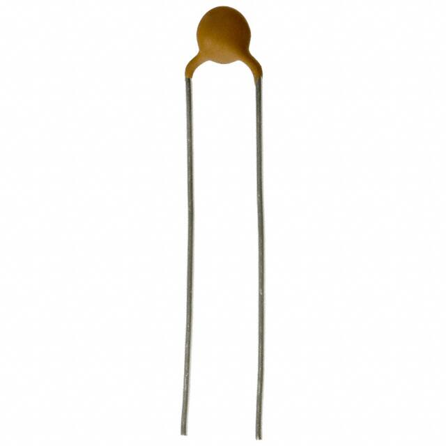


 工商网监
湘ICP备2023018690号
工商网监
湘ICP备2023018690号
