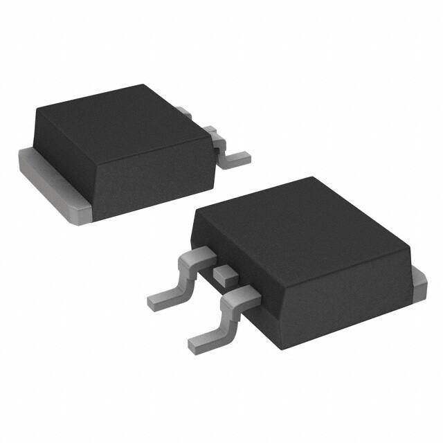
DTO25
www.vishay.com
Vishay Sfernice
Surface Mounted Power Resistor Thick Film Technology
FEATURES
• AEC-Q200 qualified
• 25 W at 25 °C case temperature
• Surface mounted resistor - TO-252 (DPAK)
style package
• Wide resistance range: 0.016 to 700 k
• Non inductive
• Resistor isolated from metal tab
• Solder reflow secure at 270 °C / 10 s, MSL = 1
ADDITIONAL RESOURCES
• Material categorization: for definitions of compliance
please see www.vishay.com/doc?99912
3D 3D
3D Models
DIMENSIONS in millimeters
8.2
2.8
6.35
0.8 ± 0.1
Footprint recommendation for
solderable contact area:
10°
1.8
8.51
4.1
3.81 1.78
12.4
7.3
6.82
1
7.87
0.6 ± 0.1
1.4 +0.2 /-0
2.54 2.54
1.2
1.6 ± 0.1
5.08
1.65
1.65
0.8 ± 0.1
Tolerance unspecified: ± 0.3
Notes
• For the assembly, we recommend the lead (Pb)-free thermal profile as per J-STD-020C
• Power dissipation is 3.2 W at an ambient temperature of 25 °C when mounted on a double sided copper board using FR4 HTG, 70 μm of
copper, 39 mm x 30 mm x 1.6 mm, with thermal vias
• For other information about dissipation, see the Application Note 52027: “Thermal Management on SMD Thick Film Resistors (D2TO20,
D2TO35, DTO25)”
STANDARD ELECTRICAL SPECIFICATIONS
MODEL
SIZE
RESISTANCE
RANGE
DTO25
TO-252 (DPAK)
0.016 to 700K
RATED POWER LIMITING ELEMENT
TOLERANCE
P25 °C
VOLTAGE UL
±%
W
V
25
MECHANICAL SPECIFICATIONS
Mechanical Protection
Resistive Element
Substrate
Connections
Weight
Molded
Thick film
Alumina
Tinned copper, Ni under layer
2 g max.
500
1, 2, 5, 10
Tolerances
Power Rating and Thermal
Resistance
Temperature Coefficient
Temperature Range
Climatic Category
Dielectric Strength
Flammability
Revision: 23-Oct-2019
CRITICAL
RESISTANCE
150
10K
ELECTRICAL SPECIFICATIONS
ENVIRONMENTAL SPECIFICATIONS
-55 °C to +150 °C
55 / 150 / 56
IEC 60695-11-5
2 applications 30 s
separated by 60 s
TEMPERATURE
COEFFICIENT
± ppm/°C
From 0.016 to 0.047 :
± 5 % and ± 10 %
> 0.047 to 0.1 :
± 2 % to ± 10 %
0.11 : ± 1 % to ± 10 %
25 W at +25 °C case
temperature RTH (j - c): 5 °C/W
See Special Feature table
± 150 ppm/°C
1500 VRMS - 1 min - 15 mA max.
(between terminals and board)
Insulation Resistance
104 M
Inductance
0.1 μH
Document Number: 51054
1
For technical questions, contact: sferfixedresistors@vishay.com
THIS DOCUMENT IS SUBJECT TO CHANGE WITHOUT NOTICE. THE PRODUCTS DESCRIBED HEREIN AND THIS DOCUMENT
ARE SUBJECT TO SPECIFIC DISCLAIMERS, SET FORTH AT www.vishay.com/doc?91000
�DTO25
www.vishay.com
Vishay Sfernice
DIMENSIONS
Standard Package
TO-252 style (DPAK)
SPECIAL FEATURES
Resistance Values
Requirement Temperature Coefficient (TCR)
(-55 °C +150 °C) IEC 60115-1
0.016
0.1
0.5
± 900 ppm/°C
± 350 ppm/°C
± 150 ppm/°C
PERFORMANCE
TESTS
Momentary Overload
Load Life
High Temperature Exposure
Temperature Cycling
Biased Humidity
Operational Life
ESD Human Body Model
CONDITIONS
REQUIREMENTS
IEC 60115-1 §4.13
1.6 Pr 5 s
US < 1.5 UL
IEC 60115-1
1000 h, 90/30 Pr at +25 °C
AEC-Q200 rev. D conditions:
MIL-STD-202 method 108
1000 h, +175 °C, unpowered
AEC-Q200 rev. D conditions:
pre-conditioning 3 reflows according
JESTD020D
JESD22 method JA-104
1000 cycles, (-55 °C to +125 °C)
dwell time 15 min
AEC-Q200 rev. D conditions:
MIL-STD-202 method 103
1000 h, 85°C, 85 % RH
AEC-Q200 rev. D conditions:
pre-conditioning 3 reflows according
JESTD020D
MIL-STD-202 method 108
1000 h, 90/30, powered, +125 °C
AEC-Q200 rev. D conditions:
AEC-Q200-002
25 kVAD
± (0.25 % + 0.005 )
± (1 % + 0.005 )
± (1 % + 0.005 )
± (0.5 % + 0.005 )
± (0.5 % + 0.005 )
± (1 % + 0.005 )
± (0.5 % + 0.005 )
Vibration
AEC-Q200 rev. D conditions:
MIL-STD-202 method 204
20 g’s for 20 min, 12 cycles
test from 10 Hz to 2000 Hz
± (0.5 % + 0.005 )
Mechanical Shock
AEC-Q200 rev. D conditions:
MIL-STD-202 method 213
100 g’s, 6 ms, 3.75 m/s
3 shocks/direction
± (0.5 % + 0.005 )
Board Flex
Terminal Strength
AEC-Q200 rev. D conditions:
AEC-Q200-005
bending 2 mm, 60 s
AEC-Q200 rev. D conditions:
AEC-Q200-006
1.8 kgf, 60 s
± (0.25 % + 0.01 )
± (0.25 % + 0.01 )
ASSEMBLY SPECIFICATIONS
For the assembly on board, we recommend the lead (Pb)-free thermal profile as per J-STD-020C
TESTS
Resistance to Soldering Heat
Moisture Sensitivity Level (MSL)
Revision: 23-Oct-2019
CONDITIONS
REQUIREMENTS
AEC-Q200 REV D
MIL-STD-202 method 210
Solder Bath method: 270 °C / 10 s
± (0.5 % + 0.005 )
IPC / JEDEC® J-STD-020C
85 °C / 85 % RH / 168 h
Level: 1
+ pass requirements of TCR
Overload and Dielectic Strength after MSL
Document Number: 51054
2
For technical questions, contact: sferfixedresistors@vishay.com
THIS DOCUMENT IS SUBJECT TO CHANGE WITHOUT NOTICE. THE PRODUCTS DESCRIBED HEREIN AND THIS DOCUMENT
ARE SUBJECT TO SPECIFIC DISCLAIMERS, SET FORTH AT www.vishay.com/doc?91000
�DTO25
www.vishay.com
Vishay Sfernice
POWER RATING
The temperature of the case should be maintained within the limits specified.
Axis Title
10000
100
1000
1st line
2nd line
2nd line
Rated Power (%)
80
60
40
100
20
10
0
0
25
50
100
150
200
Case Temperature (°C)
CHOICE OF THE BOARD
The user must choose the board according to the working conditions of the component (power, room temperature). Maximum
working temperature must not exceed 150 °C. The dissipated power is simply calculated by the following ratio:
1
T
P = ------------------------------------------------------------------------------------------R TH (j - c) + R TH (c - h) + R TH (h - a)
P:
Expressed in W
T:
Difference between maximum working temperature and room temperature
RTH (j - c): Thermal resistance value measured between resistive layer and outer side of the resistor. It is the thermal resistance
of the component: 5 °C/W.
RTH (c - h): Thermal resistance value measured between outer side of the resistor and upper side of the board. This is the thermal
resistance of the solder layer.
RTH (h - a): Thermal resistance of the board.
Example:
RTH (c - h) + RTH (h - a) for DTO25 power rating 3 W at ambient temperature +25 °C.
Thermal resistance RTH (j - c): 5 °C/W
Considering equation (1) we have:
T = 150 °C - 25 °C = 125 °C
RTH (j - c) + RTH (c - h) + RTH (h - a) = T/P = 125/3 = 41.7 °C/W
RTH (c - h) + RTH (h - a) = 41.7 °C/W - 5 °C/W = 36.7 °C/W
ACCIDENTAL OVERLOAD
In any case the applied voltage must be lower than the maximum overload voltage of Us = 750 V. The values indicated on the
graph below are applicable to resistors onto a board.
Revision: 23-Oct-2019
Document Number: 51054
3
For technical questions, contact: sferfixedresistors@vishay.com
THIS DOCUMENT IS SUBJECT TO CHANGE WITHOUT NOTICE. THE PRODUCTS DESCRIBED HEREIN AND THIS DOCUMENT
ARE SUBJECT TO SPECIFIC DISCLAIMERS, SET FORTH AT www.vishay.com/doc?91000
�DTO25
www.vishay.com
Vishay Sfernice
ENERGY CURVE at 25 °C
Axis Title
10000
100
10
1000
1st line
2nd line
2nd line
Energy (J)
1
0.1
100
0.01
10
0.001
0.0000001
0.000001
0.00001
0.0001
0.001
0.01
0.1
Overloard Duration (s)
POWER CURVE at 25 °C
Axis Title
100 000
10000
10 000
1st line
2nd line
x
Power (W)
1000
1000
100
100
10
10
0.0000001
0.000001
0.00001
0.0001
0.001
0.01
0.1
Overload Duration (s)
Single Pulse:
Repetitive or Superimposed Pulses:
These informations are for a single pulse on a cold resistor
at 25 °C (not already used for a dissipation) and for pulses
of
100 ms maximum duration.
The following formula is used to calculate the “equivalent“
energy of a repetitive pulse or the “equivalent energy“ of a
pulse on a resistor that is already dissipating power.
The formula used to calculate E is:
U
E = P x t = -------- x t
R
with:
E (J): Pulse energy
P (W): Pulse power
t (s): Pulse duration
U (V): Pulse voltage
R (): Resistor
The energy calculated must be less than that allowed by the
graph.
Revision: 23-Oct-2019
P
Pr
a
E c = E x 1 + ------
2
with:
Ec (J): Equivalent pulse energy
E (J): Known pulse energy
Pr: Resistor power rating
Pa: Mean power being dissipated
The energy calculated must be less than that allowed by the
graph and the average power dissipated (Pa) must not
exceed the continuous power of resistor.
Document Number: 51054
4
For technical questions, contact: sferfixedresistors@vishay.com
THIS DOCUMENT IS SUBJECT TO CHANGE WITHOUT NOTICE. THE PRODUCTS DESCRIBED HEREIN AND THIS DOCUMENT
ARE SUBJECT TO SPECIFIC DISCLAIMERS, SET FORTH AT www.vishay.com/doc?91000
�DTO25
www.vishay.com
Vishay Sfernice
IMPEDANCE CURVE 10 to 1 k from 100 kHz to 300 MHz
Axis Title
10000
1.90
10 Ω
1.70
1000
1.30
25 Ω
1.10
1.00
0.90
220 Ω
1st line
2nd line
2nd line
|Z|/R
1.50
47 Ω, 75 Ω, 100 Ω
470 Ω
100
0.70
0.50
1000 Ω
0.30
100 kHz
1 MHz
10 MHz
100 MHz
300 MHz
10
1000 MHz
Frequency (Hz)
PACKAGING
• Tube: max. 50 units per tube
• Reel: max. 500 units per reel
5.2
1.6
0.8
3
0.9
8.7
0.5
14.5
1
17°
R 0.5
0.8
MARKING
Model, style, resistance value (in ), tolerance (in %), manufacturing date, Vishay Sfernice trademark.
Revision: 23-Oct-2019
Document Number: 51054
5
For technical questions, contact: sferfixedresistors@vishay.com
THIS DOCUMENT IS SUBJECT TO CHANGE WITHOUT NOTICE. THE PRODUCTS DESCRIBED HEREIN AND THIS DOCUMENT
ARE SUBJECT TO SPECIFIC DISCLAIMERS, SET FORTH AT www.vishay.com/doc?91000
�DTO25
www.vishay.com
Vishay Sfernice
ORDERING INFORMATION
DTO
025
MODEL
STYLE
C
100 k
±1%
CONNECTIONS
RESISTANCE
VALUE
TOLERANCE
XXX
e3
CUSTOM DESIGN
LEAD (Pb)-FREE
Optional on request:
shape, etc
F=±1%
G=±2%
J=±5%
K = ± 10 %
SAP PART NUMBERING GUIDELINES
D
T
O
0
2
5
C
1
0
0
0
2
F
R
E
GLOBAL
MODEL
SIZE
LEADS
OHMIC VALUE
TOLERANCE
PACKAGING
DTO
025
C = surface mount
The first four digits are
significant figures and the
last digit specifies the
number of zeros to follow.
R designates decimal point.
F=1%
G=2%
J=5%
K = 10 %
R = reel
500 pieces
T = tube
50 pieces
48R70 = 48.7
48701 = 48 700
10002 = 100 000
R0100 = 0.01
R6800 = 0.68
27000 = 2700 = 2.7 k
Revision: 23-Oct-2019
3
LEAD (Pb)-FREE /
PACKAGING
E3 = standard
packaging
reel 500 or
tube 50 and
lead (Pb)-free
(pure tin)
15 = 1000 pcs.
reel and
lead (Pb)-free
(pure tin)
Document Number: 51054
6
For technical questions, contact: sferfixedresistors@vishay.com
THIS DOCUMENT IS SUBJECT TO CHANGE WITHOUT NOTICE. THE PRODUCTS DESCRIBED HEREIN AND THIS DOCUMENT
ARE SUBJECT TO SPECIFIC DISCLAIMERS, SET FORTH AT www.vishay.com/doc?91000
�Legal Disclaimer Notice
www.vishay.com
Vishay
Disclaimer
ALL PRODUCT, PRODUCT SPECIFICATIONS AND DATA ARE SUBJECT TO CHANGE WITHOUT NOTICE TO IMPROVE
RELIABILITY, FUNCTION OR DESIGN OR OTHERWISE.
Vishay Intertechnology, Inc., its affiliates, agents, and employees, and all persons acting on its or their behalf (collectively,
“Vishay”), disclaim any and all liability for any errors, inaccuracies or incompleteness contained in any datasheet or in any other
disclosure relating to any product.
Vishay makes no warranty, representation or guarantee regarding the suitability of the products for any particular purpose or
the continuing production of any product. To the maximum extent permitted by applicable law, Vishay disclaims (i) any and all
liability arising out of the application or use of any product, (ii) any and all liability, including without limitation special,
consequential or incidental damages, and (iii) any and all implied warranties, including warranties of fitness for particular
purpose, non-infringement and merchantability.
Statements regarding the suitability of products for certain types of applications are based on Vishay’s knowledge of
typical requirements that are often placed on Vishay products in generic applications. Such statements are not binding
statements about the suitability of products for a particular application. It is the customer’s responsibility to validate that a
particular product with the properties described in the product specification is suitable for use in a particular application.
Parameters provided in datasheets and / or specifications may vary in different applications and performance may vary over
time. All operating parameters, including typical parameters, must be validated for each customer application by the customer’s
technical experts. Product specifications do not expand or otherwise modify Vishay’s terms and conditions of purchase,
including but not limited to the warranty expressed therein.
Except as expressly indicated in writing, Vishay products are not designed for use in medical, life-saving, or life-sustaining
applications or for any other application in which the failure of the Vishay product could result in personal injury or death.
Customers using or selling Vishay products not expressly indicated for use in such applications do so at their own risk.
Please contact authorized Vishay personnel to obtain written terms and conditions regarding products designed for
such applications.
No license, express or implied, by estoppel or otherwise, to any intellectual property rights is granted by this document
or by any conduct of Vishay. Product names and markings noted herein may be trademarks of their respective owners.
© 2021 VISHAY INTERTECHNOLOGY, INC. ALL RIGHTS RESERVED
Revision: 01-Jan-2021
1
Document Number: 91000
�