F Series
www.vishay.com
Vishay BCcomponents
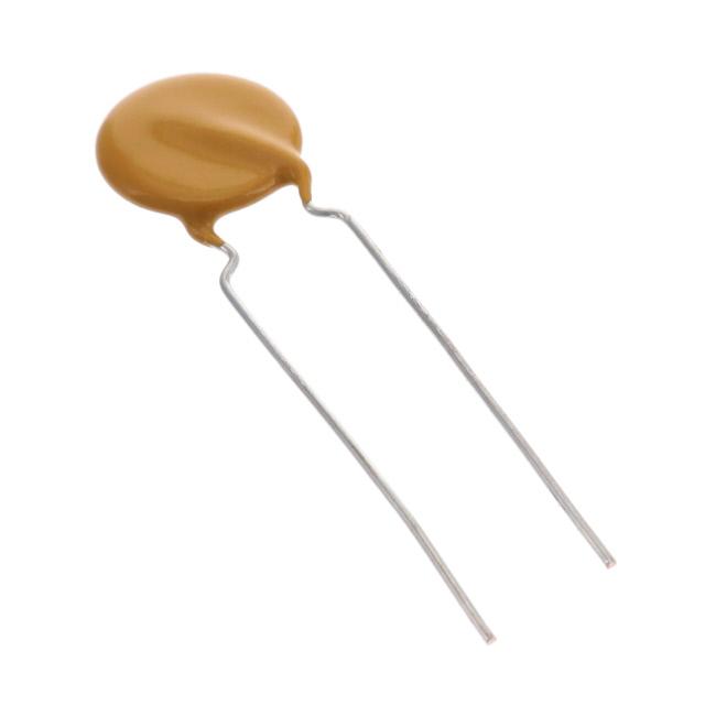
Ceramic Disc Capacitors, Class 1, Class 2,
Low Loss (0.2 %), 500 VDC, 1 kVDC, 2 kVDC, and 3 kVDC
FEATURES
•
•
•
•
•
High reliability
Low losses
High capacitance in small size
Kinked leads
Material categorization:
for definitions of compliance please see
www.vishay.com/doc?99912
APPLICATIONS
In electronic circuits where low losses and high capacitance
per volume are essential, for example:
• SMPS
• HF ballast
• Snubber and high voltage circuits
QUICK REFERENCE DATA
DESCRIPTION
Ceramic Class
Ceramic Dielectric
Voltage (VDC)
Min. Capacitance (pF)
Max. Capacitance (pF)
Mounting
VALUE
1
S3N
2000
100
4700
1000
100
2200
2
Y5R
3000
100
2700
500
100
2700
Radial
1000
100
4700
2000
100
4700
3000
100
2700
MARKING
DESIGN
Marking indicates capacitance value and tolerance in
accordance with “EIA 198” and voltage marks.
TEMPERATURE CHARACTERISTICS
The capacitors consist of a ceramic disc both sides of which
are silver-plated. Connection leads are made of tinned
copper having a diameter of 0.6 mm or 0.8 mm.
The capacitors are supplied with kinked leads and lead
spacings of 5 mm or 7.5 mm and 10 mm. Encapsulation is
made of epoxy-resin, flammable resistant in accordance
with “UL 94 V-0”
Class 1: S3N
Class 2: Y5R
CAPACITANCE RANGE
OPERATING TEMPERATURE RANGE
-30 °C to +125 °C
SECTIONAL SPECIFICATION
RATED DC VOLTAGE
IEC 60384-9, EIA 198
EXAMPLES OF MARKING CODE
Disc size (Dmax.) 6.5 mm:
RR = low loss with T.C. Y5R
101K
2 kV
Note
• Remark: no TC marking for S3N
100 pF to 4700 pF
Disc size (Dmax.) 7.5 mm:
BC
RR
102K
3 kV
500 V; 1 kV; 2 kV; 3 kV
DIELECTRIC STRENGTH
200 % of rated voltage
INSULATION RESISTANCE AT 500 VDC
10 000 M min.
TOLERANCE ON CAPACITANCE
± 10 %; ± 20 %
AGING
Typical 0.5 % per time decade
DISSIPATION FACTOR
0.2 % max.
Note
• The capacitors meet the essential requirements of “IEC 60384-9 and EIA 198”. Unless stated otherwise all electrical values apply at an
ambient temperature of 25 °C ± 3 °C, at normal atmospheric conditions
Revision: 07-Oct-16
Document Number: 28500
1
For technical questions, contact: cdc@vishay.com
THIS DOCUMENT IS SUBJECT TO CHANGE WITHOUT NOTICE. THE PRODUCTS DESCRIBED HEREIN AND THIS DOCUMENT
ARE SUBJECT TO SPECIFIC DISCLAIMERS, SET FORTH AT www.vishay.com/doc?91000
�F Series
www.vishay.com
Vishay BCcomponents
ORDERING CODES
DIELECTRIC S3N (1000 VDC / 2000 VDC)
CAP.
(pF)
100
120
150
180
220
270
330
390
470
560
680
820
1000
1200
1500
1800
2200
2700
3300
3900
4700
1000 VDC
2000 VDC
ORDERING CODE
DIAMETER
(mm max.)
THICKNESS
(mm max.)
ORDERING CODE
DIAMETER
(mm max.)
THICKNESS
(mm max.)
F101K25S3NN6###R
F121K25S3NN6###R
F151K25S3NN6###R
F181K25S3NN6###R
F221K25S3NN6###R
F271K25S3NN6###R
F331K25S3NN6###R
F391K25S3NN6###R
F471K25S3NN6###R
F561K29S3NN6###R
F681K29S3NN6###R
F821K33S3NN6###R
F102K33S3NN6###R
F122K39S3NN6###R
F152K39S3NN6###R
F182K43S3NN6###R
F222K47S3NN6###R
/
/
/
/
6.5
6.5
6.5
6.5
6.5
6.5
6.5
6.5
6.5
7.5
7.5
8.5
8.5
10.0
10.0
11.0
12.0
/
/
/
/
4.0
4.0
4.0
4.0
4.0
4.0
4.0
4.0
4.0
4.0
4.0
4.0
4.0
4.0
4.0
4.0
4.0
/
/
/
/
F101K25S3NP6###R
F121K25S3NP6###R
F151K25S3NP6###R
F181K25S3NP6###R
F221K25S3NP6###R
F271K25S3NP6###R
F331K29S3NP6###R
F391K29S3NP6###R
F471K33S3NP6###R
F561K39S3NP6###R
F681K39S3NP6###R
F821K39S3NP6###R
F102K43S3NP6###R
F122K47S3NP63K7R
F152K53S3NP63K7R
F182K53S3NP63K7R
F222K63S3NP63K7R
F272K63S3NP63K7R
F332K69S3NP63K7R
F392K75S3NP83K0R
F472K84S3NP83K0R
6.5
6.5
6.5
6.5
6.5
6.5
7.5
7.5
8.5
10.0
10.0
10.0
11.0
12.0
13.5
13.5
16.0
16.0
17.5
19.0
21.5
4.5
4.5
4.5
4.5
4.5
4.5
4.5
4.5
4.5
4.5
4.5
4.5
4.5
4.5
4.5
4.5
4.5
4.5
4.5
4.5
4.5
DIELECTRIC S3N (3000 VDC)
CAP.
(pF)
100
120
150
180
220
270
330
390
470
560
680
820
1000
1200
1500
1800
2200
2700
3000 VDC
ORDERING CODE
DIAMETER
(mm max.)
THICKNESS
(mm max.)
F101K25S3NR6###R
F121K25S3NR6###R
F151K29S3NR6###R
F181K29S3NR6###R
F221K29S3NR6###R
F271K29S3NR6###R
F331K33S3NR6###R
F391K39S3NR6###R
F471K39S3NR6###R
F561K39S3NR6###R
F681K43S3NR6###R
F821K53S3NR6###R
F102K53S3NR6###R
F122K59S3NR6###R
F152K63S3NR6###R
F182K69S3NR6###R
F222K75S3NR83K0R
F272K75S3NR83K0R
6.5
6.5
7.5
7.5
7.5
7.5
8.5
10.0
10.0
10.0
11.0
13.5
13.5
15.0
16.0
17.5
19.0
19.0
5.5
5.5
5.5
5.5
5.5
5.5
5.5
5.5
5.5
5.5
5.5
5.5
5.5
5.5
5.5
5.5
5.5
5.5
Notes
• Lead diameter is 0.6 mm
• # 5th digit is capacitance tolerance code: ± 10 % = K; ± 20 % = M
• # 13th digit is packaging code: bulk = 3; reel = T; ammo = U
• # 14th digit is lead style code: L; J; K (J is valid for 1 kV only)
• # 15th digit is lead spacing code: 5.0 mm = 5; 6.4 mm = 6; 7.5 mm = 7; 10.0 mm = 0
Revision: 07-Oct-16
Document Number: 28500
2
For technical questions, contact: cdc@vishay.com
THIS DOCUMENT IS SUBJECT TO CHANGE WITHOUT NOTICE. THE PRODUCTS DESCRIBED HEREIN AND THIS DOCUMENT
ARE SUBJECT TO SPECIFIC DISCLAIMERS, SET FORTH AT www.vishay.com/doc?91000
�F Series
www.vishay.com
Vishay BCcomponents
DIELECTRIC Y5R (500 VDC / 1000 VDC)
500 VDC
CAP.
(pF)
ORDERING CODE
100
120
150
180
220
270
330
390
470
560
680
820
1000
1200
1500
1800
2200
2700
3300
3900
4700
F101K20Y5RL6###R
F121K20Y5RL6###R
F151K20Y5RL6###R
F181K20Y5RL6###R
F221K20Y5RL6###R
F271K20Y5RL6###R
F331K20Y5RL6###R
F391K25Y5RL6###R
F471K25Y5RL6###R
F561K25Y5RL6###R
F681K25Y5RL6###R
F821K29Y5RL6###R
F102K29Y5RL6###R
F122K33Y5RL6###R
F152K33Y5RL6###R
F182K39Y5RL6###R
F222K43Y5RL63J7R
F272K47Y5RL63J7R
/
/
/
DIAMETER
(mm max.)
5.0
5.0
5.0
5.0
5.0
5.0
5.0
6.5
6.5
6.5
6.5
7.5
7.5
8.5
8.5
10.0
11.0
12.0
/
/
/
1000 VDC
THICKNESS
(mm max.)
3.5
3.5
3.5
3.5
3.5
3.5
3.5
3.5
3.5
3.5
3.5
3.5
3.5
3.5
3.5
3.5
3.5
3.5
/
/
/
ORDERING CODE
F101K25Y5RN6###R
F121K25Y5RN6###R
F151K25Y5RN6###R
F181K25Y5RN6###R
F221K25Y5RN6###R
F271K29Y5RN6###R
F331K29Y5RN6###R
F391K29Y5RN6###R
F471K29Y5RN6###R
F561K33Y5RN6###R
F681K33Y5RN6###R
F821K39Y5RN6###R
F102K39Y5RN6###R
F122K43Y5RN6###R
F152K43Y5RN6###R
F182K47Y5RN6###R
F222K53Y5RN6###R
F272K53Y5RN6###R
F332K69Y5RN6###R
F392K69Y5RN83K0R
F472K75Y5RN83K0R
DIAMETER
(mm max.)
6.5
6.5
6.5
6.5
6.5
7.5
7.5
7.5
7.5
8.5
8.5
10.0
10.0
11.0
11.0
12.0
13.5
13.5
17.5
17.5
19.0
THICKNESS
(mm max.)
4.0
4.0
4.0
4.0
4.0
4.0
4.0
4.0
4.0
4.0
4.0
4.0
4.0
4.0
4.0
4.0
4.0
4.0
4.0
4.0
4.0
DIELECTRIC Y5R (2000 VDC / 3000 VDC)
2000 VDC
CAP.
(pF)
ORDERING CODE
100
120
150
180
220
270
330
390
470
560
680
820
1000
1200
1500
1800
2200
2700
3300
3900
4700
F101K25Y5RP6###R
F121K25Y5RP6###R
F151K25Y5RP6###R
F181K29Y5RP6###R
F221K29Y5RP6###R
F271K29Y5RP6###R
F331K29Y5RP6###R
F391K33Y5RP6###R
F471K33Y5RP6###R
F561K39Y5RP6###R
F681K39Y5RP6###R
F821K43Y5RP6###R
F102K43Y5RP6###R
F122K47Y5RP6###R
F152K53Y5RP6###R
F182K59Y5RP6###R
F222K69Y5RP83K0R
F272K75Y5RP83K0R
F332K75Y5RP83K0R
F392K75Y5RP83K0R
F472K96Y5RP83K0R
DIAMETER
(mm max.)
6.5
6.5
6.5
7.5
7.5
7.5
7.5
8.5
8.5
10.0
10.0
11.0
11.0
12.0
13.5
15.0
17.5
19.0
19.0
19.0
24.5
3000 VDC
THICKNESS
(mm max.)
5.0
5.0
5.0
5.0
5.0
5.0
5.0
5.0
5.0
5.0
5.0
5.0
5.0
5.0
5.0
5.0
5.0
5.0
5.0
5.0
5.0
ORDERING CODE
F101K33Y5RR6###R
F121K33Y5RR6###R
F151K33Y5RR6###R
F181K33Y5RR6###R
F221K33Y5RR6###R
F271K33Y5RR6###R
F331K33Y5RR6###R
F391K39Y5RR6###R
F471K39Y5RR6###R
F561K43Y5RR6###R
F681K43Y5RR6###R
F821K53Y5RR6###R
F102K53Y5RR6###R
F122K59Y5RR6###R
F152K59Y5RR6###R
F182K75Y5RR6###R
F222K75Y5RR83K0R
F272K84Y5RR83K0R
/
/
/
DIAMETER
(mm max.)
8.5
8.5
8.5
8.5
8.5
8.5
8.5
10.0
10.0
11.0
11.0
13.5
13.5
15.0
15.0
19.0
19.0
21.0
/
/
/
THICKNESS
(mm max.)
5.5
5.5
5.5
5.5
5.5
5.5
5.5
5.5
5.5
5.5
5.5
5.5
5.5
5.5
5.5
5.5
5.5
5.5
/
/
/
Notes
• Lead diameter is 0.6 mm
• # 5th digit is capacitance tolerance code: ± 10 % = K; ± 20 % = M
• # 13th digit is packaging code: bulk = 3; reel = T; ammo = U
• # 14th digit is lead style code: L; J; K (J is valid for 1 kV only)
• # 15th digit is lead spacing code: 5.0 mm = 5; 6.4 mm = 6; 7.5 mm = 7; 10.0 mm = 0
Revision: 07-Oct-16
Document Number: 28500
3
For technical questions, contact: cdc@vishay.com
THIS DOCUMENT IS SUBJECT TO CHANGE WITHOUT NOTICE. THE PRODUCTS DESCRIBED HEREIN AND THIS DOCUMENT
ARE SUBJECT TO SPECIFIC DISCLAIMERS, SET FORTH AT www.vishay.com/doc?91000
�F Series
www.vishay.com
Vishay BCcomponents
PACKAGING
PACKAGING TYPE
LEAD SPACE
(mm)
SIZE CODE
Bulk
(long lead L 25.4 mm)
VOLTAGE
(VDC)
20 to 25
1000
29 to 39
1000
43 to 47
all
BOX DIMENSIONS
LxWxH
SPQ
all
1000
53 to 75
245 x 120 x 65
500
84 to 96
250
< 500
2500
500 WV 2000
2000
3000
1000
7.5
all
1000
all
all
1000
< 500
2000
500 WV < 2000
2000
2000 and 3000
1500
7.5
all
1500
360 x 330 x 55
all
all
1500
335 x 290 x 50
6.4
47
Tape and reel
53
6.4
47
370 x 370 x 60
335 x 240 x 50
335 x 290 x 50
Ammopack
53
Note
• The capacitors are supplied in bulk packaging (cardboard boxes), in tape on reel or in ammopack
D
P2
P
Δh
Δh
Δs
ΔP
Δs
ΔP
H1
W2
H0
L
W1
W0 W
A
e
Direction of unreeling
Ød
P1
F
P0
D0
t1
t
detail A
Kinked capacitors on tape, lead spacing 5.0 mm (0.2) or 7.5 mm (0.3)
Revision: 07-Oct-16
Document Number: 28500
4
For technical questions, contact: cdc@vishay.com
THIS DOCUMENT IS SUBJECT TO CHANGE WITHOUT NOTICE. THE PRODUCTS DESCRIBED HEREIN AND THIS DOCUMENT
ARE SUBJECT TO SPECIFIC DISCLAIMERS, SET FORTH AT www.vishay.com/doc?91000
�F Series
www.vishay.com
Vishay BCcomponents
DIMENSIONS OF TAPE
SYMBOL
PARAMETER
D
d
P (1)
P0
P
P1 (2)
P2 (2)
F
h
W
W0
W1
W2
H0
H1
e
L
D0
t
t1
Body diameter
Lead diameter
Pitch between capacitors
Feed-hole pitch
Plane deviation
Feed-hole center to lead center
Feed-hole center to component center
Lead spacing
Component alignment
Tape width
Hold-down tape width
Hole position
Hold-down tape margin
Height to seating plane
Maximum component height
Lead end protrusion
Maximum length of snipped lead
Feed-hole diameter
Total tape thickness
Maximum thickness of tape and wires
DIMENSIONS (mm)
FEED-HOLE PITCH
FEED-HOLE PITCH
P0 = 15.0
P0 = 12.7
11.0 max.
14.0 max.
0.6 0.05
0.6 0.05
12.7 1.0
15.0 1.0
12.7 0.3
15.0 0.3
1.0 max.
1.0 max.
3.85 0.7
3.75 0.7
6.35 1.3
7.5 1.5
5.0 + 0.6/0.4
7.5 0.6/- 0.4
0 1.0
0 1.0
18.0 + 1.0/0.5
18.0 + 1.0/ 0.5
5.0 min.
5.0 min.
9.0 + 0.75/0.5
9.0 + 0.75/ 0.5
3.0 max.
3.0 max.
16.0 0.5
16.0 0.5
32.0
40.0
1.0 max.
1.0 max.
11.0
11.0
4.0 0.2
4.0 0.2
0.9 max.
0.9 max.
1.5 max.
1.5 max.
Notes
(1) Cumulative pitch error: 1 mm/20 pitches
(2) Obliquity maximum 3°
REEL AND TAPE DATA in millimeters
51 max.
355.6 ± 2.0
W
28 ± 1.5
8.0
45 max.
L
H
Reel with capacitors on tape
Ammopack with capacitors on tape
DIMENSIONS OF AMMOPACK
DISC SIZE
(DMAX.)
PARAMETER
Taping pitch
L
W
H
Revision: 07-Oct-16
6.5 mm to 11.0 mm
12.7
335
290
50
UNIT
12.0 mm to 13.5 mm
15.0
360
330
55
mm
mm
mm
mm
Document Number: 28500
5
For technical questions, contact: cdc@vishay.com
THIS DOCUMENT IS SUBJECT TO CHANGE WITHOUT NOTICE. THE PRODUCTS DESCRIBED HEREIN AND THIS DOCUMENT
ARE SUBJECT TO SPECIFIC DISCLAIMERS, SET FORTH AT www.vishay.com/doc?91000
�F Series
www.vishay.com
Vishay BCcomponents
Dissipation factor (x 10-4)
60
ΔC (%)
C
Y5R
0
140
Y5R
120
100
80
60
40
20
-60
0
-40
-20
0
20
1 kHz
10 kHz
40
60
100
80
100 kHz
1 MHz
120 140
T (°C)
0
Dissipation factor (%)
ΔC (%)
C
S3N
40
20
100
120
140
Tamb (°C)
14
S3N
12
10
8
6
0
4
-20
2
-40
-60
60
80
100 kHz
1 MHz
Typical dissipation factor as a function of
temperature and frequency
Typical capacitance change as a function of
temperature and frequency
100
20
40
1 kHz
10 kHz
-75
-50
-25
1 kHz
600 kHz
0
25
50
75
100
100 kHz
1 MHz
0
125 150
T (°C)
-75
-50 -25
1 kHz
600 kHz
0
25
50
100 kHz
1 MHz
75
100
125 150
T (°C)
Typical dissipation factor as a function of
temperature and frequency
Typical capacitance change as a function of
temperature and frequency
ΔC (%)
C
0
-2
-4
-6
-8
-10
1
10
102
103
104
105
t (h)
Aging rate as a function of time
Revision: 07-Oct-16
Document Number: 28500
6
For technical questions, contact: cdc@vishay.com
THIS DOCUMENT IS SUBJECT TO CHANGE WITHOUT NOTICE. THE PRODUCTS DESCRIBED HEREIN AND THIS DOCUMENT
ARE SUBJECT TO SPECIFIC DISCLAIMERS, SET FORTH AT www.vishay.com/doc?91000
�Legal Disclaimer Notice
www.vishay.com
Vishay
Disclaimer
ALL PRODUCT, PRODUCT SPECIFICATIONS AND DATA ARE SUBJECT TO CHANGE WITHOUT NOTICE TO IMPROVE
RELIABILITY, FUNCTION OR DESIGN OR OTHERWISE.
Vishay Intertechnology, Inc., its affiliates, agents, and employees, and all persons acting on its or their behalf (collectively,
“Vishay”), disclaim any and all liability for any errors, inaccuracies or incompleteness contained in any datasheet or in any other
disclosure relating to any product.
Vishay makes no warranty, representation or guarantee regarding the suitability of the products for any particular purpose or
the continuing production of any product. To the maximum extent permitted by applicable law, Vishay disclaims (i) any and all
liability arising out of the application or use of any product, (ii) any and all liability, including without limitation special,
consequential or incidental damages, and (iii) any and all implied warranties, including warranties of fitness for particular
purpose, non-infringement and merchantability.
Statements regarding the suitability of products for certain types of applications are based on Vishay’s knowledge of
typical requirements that are often placed on Vishay products in generic applications. Such statements are not binding
statements about the suitability of products for a particular application. It is the customer’s responsibility to validate that a
particular product with the properties described in the product specification is suitable for use in a particular application.
Parameters provided in datasheets and / or specifications may vary in different applications and performance may vary over
time. All operating parameters, including typical parameters, must be validated for each customer application by the customer’s
technical experts. Product specifications do not expand or otherwise modify Vishay’s terms and conditions of purchase,
including but not limited to the warranty expressed therein.
Except as expressly indicated in writing, Vishay products are not designed for use in medical, life-saving, or life-sustaining
applications or for any other application in which the failure of the Vishay product could result in personal injury or death.
Customers using or selling Vishay products not expressly indicated for use in such applications do so at their own risk.
Please contact authorized Vishay personnel to obtain written terms and conditions regarding products designed for
such applications.
No license, express or implied, by estoppel or otherwise, to any intellectual property rights is granted by this document
or by any conduct of Vishay. Product names and markings noted herein may be trademarks of their respective owners.
© 2017 VISHAY INTERTECHNOLOGY, INC. ALL RIGHTS RESERVED
Revision: 08-Feb-17
1
Document Number: 91000
�