0
登录后你可以
  • 下载海量资料
  • 学习在线课程
  • 观看技术视频
  • 写文章/发帖/加入社区
会员中心
创作中心
发布
  • 发文章

  • 发资料

  • 发帖

  • 提问

  • 发视频

创作活动
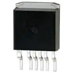
HFA08TB60STRR

HFA08TB60STRR

  • 厂商:

    TFUNK(威世)

  • 封装:

    TO263

  • 描述:

    DIODE GEN PURP 600V 8A D2PAK

  • 详情介绍
  • 数据手册
  • 价格&库存
HFA08TB60STRR 数据手册
HFA08TB60S Vishay High Power Products HEXFRED® Ultrafast Soft Recovery Diode, 8 A FEATURES • • • • • • Base cathode + 2 N/C 1 3 Ultrafast recovery Ultrasoft recovery Very low IRRM Very low Qrr Specified at operating conditions Designed and qualified for industrial level BENEFITS - • • • • • Anode Reduced RFI and EMI Reduced power loss in diode and switching transistor Higher frequency operation Reduced snubbing Reduced parts count DESCRIPTION D2PAK HFA08TB60S is a state of the art ultrafast recovery diode. Employing the latest in epitaxial construction and advanced processing techniques it features a superb combination of characteristics which result in performance which is unsurpassed by any rectifier previously available. With basic ratings of 600 V and 8 A continuous current, the HFA08TB60S is especially well suited for use as the companion diode for IGBTs and MOSFETs. In addition to ultrafast recovery time, the HEXFRED® product line features extremely low values of peak recovery current (IRRM) and does not exhibit any tendency to “snap-off” during the tb portion of recovery. The HEXFRED features combine to offer designers a rectifier with lower noise and significantly lower switching losses in both the diode and the switching transistor. These HEXFRED advantages can help to significantly reduce snubbing, component count and heatsink sizes. The HEXFRED HFA08TB60S is ideally suited for applications in power supplies (PFC boost diode) and power conversion systems (such as inverters), motor drives, and many other similar applications where high speed, high efficiency is needed. PRODUCT SUMMARY VR 600 V VF at 8 A at 25 °C 1.7 V IF(AV) 8A trr (typical) 18 ns TJ (maximum) 150 °C Qrr (typical) 65 nC dI(rec)M/dt (typical) 240 A/µs IRRM 5.0 A ABSOLUTE MAXIMUM RATINGS PARAMETER SYMBOL Cathode to anode voltage TEST CONDITIONS VR Maximum continuous forward current IF TC = 100 °C VALUES UNITS 600 V 8.0 Single pulse forward current IFSM 60 Maximum repetitive forward current IFRM 24 Maximum power dissipation PD Operating junction and storage temperature range Document Number: 93045 Revision: 22-Oct-08 TC = 25 °C 36 TC = 100 °C 14 TJ, TStg For technical questions, contact: diodes-tech@vishay.com - 55 to + 150 A W °C www.vishay.com 1 HFA08TB60S Vishay High Power Products HEXFRED® Ultrafast Soft Recovery Diode, 8 A ELECTRICAL SPECIFICATIONS (TJ = 25 °C unless otherwise specified) PARAMETER SYMBOL TEST CONDITIONS Cathode to anode breakdown voltage VBR IR = 100 µA Maximum forward voltage VFM IF = 16 A IF = 8.0 A MIN. TYP. MAX. 600 - - - 1.4 1.7 - 1.7 2.1 IF = 8.0 A, TJ = 125 °C - 1.4 1.7 VR = VR rated - 0.3 5.0 - 100 500 See fig. 1 UNITS V Maximum reverse leakage current IRM Junction capacitance CT VR = 200 V See fig. 3 - 10 25 pF Series inductance LS Measured lead to lead 5 mm from package body - 8.0 - nH UNITS TJ = 125 °C, VR = 0.8 x VR rated See fig. 2 µA DYNAMIC RECOVERY CHARACTERISTICS (TJ = 25 °C unless otherwise specified) PARAMETER Reverse recovery time See fig. 5, 6 Peak recovery current Reverse recovery charge See fig. 7 Peak rate of fall of recovery current during tb See fig. 8 SYMBOL TEST CONDITIONS trr IF = 1.0 A, dIF/dt = 200 A/µs, VR = 30 V MIN. TYP. MAX. - 18 - trr1 TJ = 25 °C - 37 55 trr2 TJ = 125 °C - 55 90 IRRM1 TJ = 25 °C - 3.5 5.0 IRRM2 TJ = 125 °C - 4.5 8.0 - 65 138 - 124 360 IF = 8.0 A dIF/dt = 200 A/µs VR = 200 V ns A Qrr1 TJ = 25 °C Qrr2 TJ = 125 °C dI(rec)M/dt1 TJ = 25 °C - 240 - dI(rec)M/dt2 TJ = 125 °C - 210 - MIN. TYP. MAX. UNITS - - 300 °C - - 3.5 - - 80 - 2.0 - g - 0.07 - oz. nC A/µs THERMAL - MECHANICAL SPECIFICATIONS PARAMETER SYMBOL Lead temperature Tlead Thermal resistance, junction to case RthJC Thermal resistance, junction to ambient RthJA TEST CONDITIONS 0.063" from case (1.6 mm) for 10 s K/W Typical socket mount Weight Marking device www.vishay.com 2 Case style D2PAK For technical questions, contact: diodes-tech@vishay.com HFA08TB60S Document Number: 93045 Revision: 22-Oct-08 HFA08TB60S 100 1000 TJ = 150 °C 10 TJ = 150 °C TJ = 125 °C TJ = 25 °C 1 0.1 0.4 100 IR - Reverse Current (µA) IF - Instantaneous Forward Current (A) HEXFRED® Vishay High Power Products Ultrafast Soft Recovery Diode, 8 A TJ = 125 °C 10 1 0.1 TJ = 25 °C 0.01 0.001 0.8 1.2 1.6 2.0 2.4 2.8 0 3.2 100 300 200 500 400 600 VFM - Forward Voltage Drop (V) VR - Reverse Voltage (V) Fig. 1 - Maximum Forward Voltage Drop vs. Instantaneous Forward Current Fig. 2 - Typical Reverse Current vs. Reverse Voltage CT - Junction Capacitance (pF) 100 TJ = 25 °C 10 1 1 10 100 1000 VR - Reverse Voltage (V) Fig. 3 - Typical Junction Capacitance vs. Reverse Voltage ZthJC - Thermal Response 10 1 PDM 0.1 Single pulse (thermal response) 0.01 0.00001 0.0001 t1 D = 0.50 D = 0.20 D = 0.10 D = 0.05 D = 0.02 D = 0.01 0.001 t2 Notes: 1. Duty factor D = t1/t2 2. Peak TJ = PDM x ZthJC + TC 0.01 0.1 1 t1 - Rectangular Pulse Duration (s) Fig. 4 - Maximum Thermal Impedance ZthJC Characteristics Document Number: 93045 Revision: 22-Oct-08 For technical questions, contact: diodes-tech@vishay.com www.vishay.com 3 HFA08TB60S Vishay High Power Products HEXFRED® Ultrafast Soft Recovery Diode, 8 A 80 500 IF = 16 A IF = 8 A IF = 4 A 400 Qrr (nC) trr (ns) 60 40 VR = 200 V TJ = 125 °C TJ = 25 °C 300 200 IF = 16 A IF = 8 A IF = 4 A 20 100 VR = 200 V TJ = 125 °C TJ = 25 °C 0 100 0 100 1000 dIF/dt (A/µs) dIF/dt (A/µs) Fig. 5 - Typical Reverse Recovery Time vs. dIF/dt Fig. 7 - Typical Stored Charge vs. dIF/dt 20 10 000 VR = 200 V TJ = 125 °C TJ = 25 °C dI(rec)M/dt (A/µs) 15 Irr (A) 1000 IF = 16 A IF = 8 A IF = 4 A 10 IF = 16 A IF = 8 A IF = 4 A 1000 5 VR = 200 V TJ = 125 °C TJ = 25 °C 0 100 www.vishay.com 4 1000 100 100 1000 dIF/dt (A/µs) dIF/dt (A/µs) Fig. 6 - Typical Recovery Current vs. dIF/dt Fig. 8 - Typical dI(rec)M/dt vs. dIF/dt For technical questions, contact: diodes-tech@vishay.com Document Number: 93045 Revision: 22-Oct-08 HFA08TB60S HEXFRED® Vishay High Power Products Ultrafast Soft Recovery Diode, 8 A VR = 200 V 0.01 Ω L = 70 µH D.U.T. dIF/dt adjust D IRFP250 G S Fig. 9 - Reverse Recovery Parameter Test Circuit (3) trr IF ta tb 0 Qrr (2) IRRM (4) 0.5 IRRM dI(rec)M/dt (5) 0.75 IRRM (1) dIF/dt (1) dIF/dt - rate of change of current through zero crossing (2) IRRM - peak reverse recovery current (3) trr - reverse recovery time measured from zero crossing point of negative going IF to point where a line passing through 0.75 IRRM and 0.50 IRRM extrapolated to zero current. (4) Qrr - area under curve defined by trr and IRRM Qrr = trr x IRRM 2 (5) dI(rec)M/dt - peak rate of change of current during tb portion of trr Fig. 10 - Reverse Recovery Waveform and Definitions LINKS TO RELATED DOCUMENTS Dimensions http://www.vishay.com/doc?95046 Part marking information http://www.vishay.com/doc?95054 Packaging information http://www.vishay.com/doc?95032 Document Number: 93045 Revision: 22-Oct-08 For technical questions, contact: diodes-tech@vishay.com www.vishay.com 5 Legal Disclaimer Notice Vishay Disclaimer All product specifications and data are subject to change without notice. Vishay Intertechnology, Inc., its affiliates, agents, and employees, and all persons acting on its or their behalf (collectively, “Vishay”), disclaim any and all liability for any errors, inaccuracies or incompleteness contained herein or in any other disclosure relating to any product. Vishay disclaims any and all liability arising out of the use or application of any product described herein or of any information provided herein to the maximum extent permitted by law. The product specifications do not expand or otherwise modify Vishay’s terms and conditions of purchase, including but not limited to the warranty expressed therein, which apply to these products. No license, express or implied, by estoppel or otherwise, to any intellectual property rights is granted by this document or by any conduct of Vishay. The products shown herein are not designed for use in medical, life-saving, or life-sustaining applications unless otherwise expressly indicated. Customers using or selling Vishay products not expressly indicated for use in such applications do so entirely at their own risk and agree to fully indemnify Vishay for any damages arising or resulting from such use or sale. Please contact authorized Vishay personnel to obtain written terms and conditions regarding products designed for such applications. Product names and markings noted herein may be trademarks of their respective owners. Document Number: 91000 Revision: 18-Jul-08 www.vishay.com 1
HFA08TB60STRR
物料型号: HFA08TB60S

器件简介: - 该二极管是采用最新的外延结构和先进加工技术制造的超快恢复二极管。 - 具有600V和8A的基准额定值,非常适合用作IGBT和MOSFET的配套二极管。

引脚分配: - 1号引脚:阳极(Anode) - 2号引脚:阴极(Base) - 3号引脚:空脚(N/C)

参数特性: - 正向电压(VF)在8A和25°C时为1.7V。 - 恢复时间(tr)典型值为18纳秒。 - 反向恢复电荷(Qr)典型值为65纳秒。

功能详解: - 该二极管具有超快恢复时间和超软恢复特性,非常低的峰值恢复电流(IRRM)和非常低的Qrr。 - 专为工业级设计和认证。

应用信息: - 适用于电源供应(PFC升压二极管)、功率转换系统(如逆变器)、电机驱动等需要高速、高效率的应用。

封装信息: - 封装类型为D2PAK。

电气规格: - 包括正向电压降、反向漏电流、结电容、串联电感等参数。

动态恢复特性: - 包括反向恢复时间、峰值恢复电流、反向恢复电荷和恢复电流下降速率等参数。

热机械规格: - 包括引脚温度、结到外壳的热阻、结到环境的热阻、重量和标记设备等参数。

相关文档链接: - 提供了尺寸、部件标记信息和包装信息的链接。

法律免责声明: - Vishay保留随时更改产品规格和数据的权利,并对任何错误、不准确或不完整信息不承担任何责任。
HFA08TB60STRR 价格&库存

很抱歉,暂时无法提供与“HFA08TB60STRR”相匹配的价格&库存,您可以联系我们找货

免费人工找货