HVCC Series
www.vishay.com
Vishay Roederstein
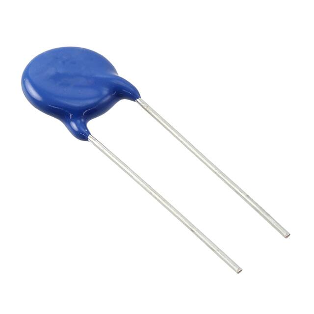
High Voltage Ceramic Capacitors
Radial-Leaded Singlelayer Disc
FEATURES
• Ceramic singlelayer DC disc / AC disc capacitor
• High reliability
• High capacitance values up to 2 nF
• Small sizes
• Low losses
• Radial leads
• Material categorization: for definitions of compliance
please see www.vishay.com/doc?99912
DESIGN SUPPORT TOOLS
click logo to get started
OPTIONS (on request)
• 20 kV rated voltage
• ± 10 % tolerance on nominal C-value
Models
Available
• Customized lead styles
APPLICATIONS
QUICK REFERENCE DATA
DESCRIPTION
Ceramic Class
Ceramic Dielectric
Temperature Coefficient
of Capacitance
Voltage (Urated, DC)
Min. Capacitance (pF)
Max. Capacitance (pF)
Capacitance
Tolerance
Max. Dissipation
Factor (%)
Min. Insulation
Resistance (G)
Operating
Temperature (°C)
Mounting
High voltage power supplies for x-ray sources and pulsed
lasers
VALUE
2
Y6P
• Baggage scanner
± 10 % within -30 °C and +105 °C
10 000
100
2000
15 000
100
2000
± 20 %
1.0 and 1.5
200
-30 to +105
Radial
• Medical x-ray
• Industrial laser
DESIGN
The capacitors consist of a ceramic disc of which both sides
are silver-plated. Connection leads are made of tinned
copper clad steel wire having diameters of 0.02" (0.6 mm)
and 0.03" (0.8 mm).
The capacitors may be supplied with straight leads having
lead spacing of 0.37" (9.5 mm) and 0.49" (12.5 mm).
Coating is made of flame retardant epoxy resin in
accordance with “UL 94 V-0”.
INSULATION RESISTANCE
Min. 200 000 M at 500 VDC / 60 s max.
CAPACITANCE RANGE
100 pF to 2000 pF
TOLERANCE ON CAPACITANCE
± 20 %
DIELECTRIC STRENGTH BETWEEN LEADS
1.5 x Urated, DC for maximum 60 s in insulation liquid
DISSIPATION FACTOR
1 nF: max. 1.0 %
> 1 nF: max. 1.5 %
Test voltage: customer re-test 1.35 x Urated, DC for maximum
60 s in insulated liquid
Note
• Considered as destructive test
OPERATING TEMPERATURE RANGE
-30 °C to +105 °C
CERAMIC DIELECTRIC
Y6P (± 10 % within -30 °C and +105 °C)
Revision: 30-Oct-2018
Document Number: 23144
1
For technical questions, contact: slcap@vishay.com
THIS DOCUMENT IS SUBJECT TO CHANGE WITHOUT NOTICE. THE PRODUCTS DESCRIBED HEREIN AND THIS DOCUMENT
ARE SUBJECT TO SPECIFIC DISCLAIMERS, SET FORTH AT www.vishay.com/doc?91000
�HVCC Series
www.vishay.com
Vishay Roederstein
DIMENSIONS in millimeters (inches)
Thickness
4.0 (0.15)
Diameter
Lead length
Width
ad
Le ace
p
s
Wire size
ORDERING INFORMATION, CERAMIC 10 kVDC
C
(pF)
TOL.
(%)
MAXIMUM MAXIMUM
DIAMETER THICKNESS
mm
INCH
LEAD SPACE
± 1 mm
(± 0.04")
mm
INCH
WIRE SIZE
± 0.05 mm
(± 0.002") (1)
mm
INCH
LEAD LENGTH
-3 mm
(-0.12")
mm
INCH
WIDTH
± 0.5 mm
(± 0.02")
ORDERING CODE
mm
INCH
mm
INCH
100
8
0.31
5.3
0.21
HVCC103Y6P101####
150
8
0.31
4.5
0.18
HVCC103Y6P151####
220
9
0.35
4.5
0.18
HVCC103Y6P221####
330
10
0.39
4.3
0.17
HVCC103Y6P331####
12
0.47
4.3
0.17
HVCC103Y6P471####
680
13
0.51
3.8
0.15
HVCC103Y6P681####
1000
15
0.59
3.8
0.15
HVCC103Y6P102####
1500
17
0.67
3.8
0.15
HVCC103Y6P152####
2000
18
0.71
3.8
0.15
HVCC103Y6P202####
470
± 20
7.5
0.30
12.5
and
9.5
0.49
and
0.37
0.8
and
0.6
0.032
and
0.024
30
1.18
ORDERING INFORMATION, CERAMIC 15 kVDC
C
(pF)
TOL.
(%)
MAXIMUM MAXIMUM
DIAMETER THICKNESS
mm
INCH
LEAD SPACE
± 1 mm
(± 0.04")
mm
INCH
WIRE SIZE
± 0.05 mm
(± 0.002") (1)
mm
INCH
LEAD LENGTH
-3 mm
(-0.12")
mm
INCH
WIDTH
± 0.5 mm
(± 0.02")
ORDERING CODE
mm
INCH
mm
INCH
100
8
0.31
5.3
0.21
HVCC153Y6P101####
150
8
0.31
4.5
0.18
HVCC153Y6P151####
220
9
0.35
4.5
0.18
HVCC153Y6P221####
330
10
0.39
4.3
0.17
HVCC153Y6P331####
12
0.47
4.3
0.17
HVCC153Y6P471####
680
13
0.51
4.3
0.17
HVCC153Y6P681####
1000
15
0.59
4.3
0.17
HVCC153Y6P102####
1500
19
0.75
4.3
0.17
HVCC153Y6P152####
2000
19
0.75
4.3
0.17
HVCC153Y6P202####
470
± 20
8
0.31
12.5
and
9.5
0.49
and
0.37
0.8
and
0.6
0.032
and
0.024
30
1.18
Notes
• 20 kV, customized lead styles, and ± 10 % tolerance are available upon request
(1) #20 AWG = 0.8 mm
#22 AWG = 0.6 mm
Revision: 30-Oct-2018
Document Number: 23144
2
For technical questions, contact: slcap@vishay.com
THIS DOCUMENT IS SUBJECT TO CHANGE WITHOUT NOTICE. THE PRODUCTS DESCRIBED HEREIN AND THIS DOCUMENT
ARE SUBJECT TO SPECIFIC DISCLAIMERS, SET FORTH AT www.vishay.com/doc?91000
�HVCC Series
www.vishay.com
Vishay Roederstein
MARKING
Sample
HVCC
102M
15kV
Y6P / YY WW
YY - Year
WW - Week
ORDERING CODE
H
V
C
C
1
1
5
3
Y
6
2
P
1
0
3
2
M
4
E
5
A
X
6
7
1
2
3
4
5
6
7
SERIES
(HIGH VOLTAGE
CERAMIC CAPACITOR)
RATED VOLTAGE
TEMPERATURE
CHARACTERISTICS
CAPACITANCE
VALUE
CAPACITANCE
TOLERANCE
1st DIGIT:
LEAD TYPE /
LEAD SPACING /
GAUGE
PACKAGING
2nd DIGIT:
LEAD LENGTH
LEAD TYPE (position 6)
STANDARD TYPE
LEAD TYPE
LEAD SPACING
(mm)
AA
Straight LL
9.5 ± 1.0
0.8
20
TCCSW
30 - 3
AB
Straight SL
9.5 ± 1.0
0.8
20
TCCSW
3.5 ± 1
BA
Inline LL
9.5 ± 1.0
0.8
20
TCCSW
30 - 3
BB
Inline SL
9.5 ± 1.0
0.8
20
TCCSW
3.5 ± 1
CODE
LEAD DIAMETER
(mm)
# GAUGE
MATERIAL
LEAD LENGTH
(mm)
CA
Straight LL
9.5 ± 1.0
0.6
22
TCCSW
30 - 3
CB
Straight SL
9.5 ± 1.0
0.6
22
TCCSW
3.5 ± 1
DA
Inline LL
9.5 ± 1.0
0.6
22
TCCSW
30 - 3
DB
Inline SL
9.5 ± 1.0
0.6
22
TCCSW
3.5 ± 1
EA
Straight LL
12.5 ± 1.0
0.8
20
TCCSW
30 - 3
EB
Straight SL
12.5 ± 1.0
0.8
20
TCCSW
3.5 ± 1
FA
Inline LL
12.5 ± 1.0
0.8
20
TCCSW
30 - 3
FB
Inline SL
12.5 ± 1.0
0.8
20
TCCSW
3.5 ± 1
GA
Straight LL
12.5 ± 1.0
0.6
22
TCCSW
30 - 3
GB
Straight SL
12.5 ± 1.0
0.6
22
TCCSW
3.5 ± 1
HA
Inline LL
12.5 ± 1.0
0.6
22
TCCSW
30 - 3
HB
Inline SL
12.5 ± 1.0
0.6
22
TCCSW
3.5 ± 1
Notes
• 1th digit: lead type / lead spacing / gauge
2nd digit: A = long leads, B = short leads
• LL = long leads
SL = short leads
• TCCSW = tinned copper clad steel wire
Revision: 30-Oct-2018
Document Number: 23144
3
For technical questions, contact: slcap@vishay.com
THIS DOCUMENT IS SUBJECT TO CHANGE WITHOUT NOTICE. THE PRODUCTS DESCRIBED HEREIN AND THIS DOCUMENT
ARE SUBJECT TO SPECIFIC DISCLAIMERS, SET FORTH AT www.vishay.com/doc?91000
�HVCC Series
www.vishay.com
Vishay Roederstein
PACKAGING (position 7)
CODE
VERSION
X
Bulk
PERFORMANCE
NO.
PARAMETER
SPECIFICATION
TEST CONDITIONS
METHOD AND NOTES
1
Capacitance
Tol. K = ± 10 % at 1000 h
Tol. M = ± 20 % at 1000 h
2
Dissipation factor
DF / tan = max. 1.5 %
3
Insulation resistance
IR = min. 10 G
t = 5 s
U = 500 VDC ± 10 VDC
NOTE: very high resistances are sensitive to the surrounding
area may lead to unstable measurement values
4
Dielectric strength
(between lead wires)
U1 = +1.75 x URDC
U2 = -1.75 x URDC
tU1 = tU2 = 5 s
Imax. = 50 mA
1. Apply +1.75 x URDC for max. 5 s
2. Unload part (Imax. = 50 mA)
3. Apply -1.75 x URDC for max. 5 s
4. Unload part (Imax. = 50 mA)
5. Avoid current spikes higher than 50 mA
5
Appearance and marking
No visible damage.
The marking shall be legible
Visual inspection by AOI
6
Dimensions
Dimensions are within specification
Measurement by AOI
7.1
Temperature characteristics /
TCC
EIA code = Y6P
C/C0 = ± 10 %
Temp. range = -30 °C to 105 °C
7.2
Temperature characteristics /
TCDF
DF / tan = max. 1.5 %
Temp. range = 20 °C to 105 °C
8.1
Dielectric strength
between lead wires
8.2
8.3
Dielectric strength of
body insulation
U = 1.5 x URDC
t = 60 s
Imax. = 50 mA
U = 1.5 x UNAC
t = 60 s
U = 5000 VDC
t = 60 s
Components are measured with a LCR-meter. Consider aging
of ceramic. Given tolerance is valid 1000 h ± 24 h after last
heating. Before and after that moment, aging offset has to be
considered.
(See general information for further instructions)
Measurement is done from cooler temperatures to hotter
temperatures in reasonable temperature steps. Other way
round you get have to consider deaging effects.
1. Apply 1.5 x U for max. 60 s
2. Avoid current spikes higher than 50 mA
3. Voltage breakdowns are not accepted
NOTE: considered as destructive test
1. Connect both lead wires together
2. Dip component headfirst into a bath with oil and
metal balls (fig.)
3. Apply voltage between lead wires and metal balls
U
(V)
90 %
9
Pulse test
tr = 1.2 μs
tf = 50 μs
U = 1.5 x URDC
n = 50 x single polarity
100 %
Rise time:
ts = 1.2 μs ± 30 %
50 %
Half value time:
tr = 50 μs ± 20 %
Over swing:
ü 50 Hz) does also lead to higher losses and to self heating of the component. The surface
temperature of the component must be kept below the maximum operating temperature. Adaptation of the insulation media
might increase cooling effect.
6. CAUTION
6.1 OPERATING VOLTAGE AND FREQUENCY CHARACTERISTIC
When sinusoidal or ripple voltage applied to DC ceramic disc capacitors, be sure to maintain the peak-to-peak value or the peak
value of the sum of both AC + DC within the rated voltage.
When start or stop applying the voltage, resonance may generate irregular voltage.
When rectangular or pulse wave voltage is applied to DC ceramic disc capacitors, the self-heating generated by the capacitor
is higher than the sinusoidal application with the same frequency. The allowable voltage rating for the rectangular or pulse wave
corresponds approximately with the allowable voltage of a sinusoidal wave with the double fundamental frequency.
The allowable voltage varies, depending on the voltage and the waveform.
Diagrams of the limiting values are available for each capacitor series on request.
VOLTAGE
Waveform figure
DC
V0-p
DC + AC
AC
Vp-p
V0-p
0
0
0
6.2 OPERATING TEMPERATURE AND SELF-GENERATED HEAT
The surface temperature of the capacitors must not exceed the upper limit of its rated operating temperature.
During operation in a high-frequency circuit or a pulse signal circuit, the capacitor itself generate heat due to dielectric losses.
Applied voltage should be the load such as self-generated heat is within 20 °C on the condition of environmental temperature
25 °C.
Note, that excessive heat may lead to deterioration of the capacitor’s characteristics.
RELATED DOCUMENTS
General Information
Product Sheet
Infographic
www.vishay.com/doc?22001
www.vishay.com/doc?
www.vishay.com/doc?48450
SAMPLE KIT
Part Number
Link
Revision: 30-Oct-2018
HVCC-KIT-HV
www.vishay.com/doc?45251
Document Number: 23144
8
For technical questions, contact: slcap@vishay.com
THIS DOCUMENT IS SUBJECT TO CHANGE WITHOUT NOTICE. THE PRODUCTS DESCRIBED HEREIN AND THIS DOCUMENT
ARE SUBJECT TO SPECIFIC DISCLAIMERS, SET FORTH AT www.vishay.com/doc?91000
�Legal Disclaimer Notice
www.vishay.com
Vishay
Disclaimer
ALL PRODUCT, PRODUCT SPECIFICATIONS AND DATA ARE SUBJECT TO CHANGE WITHOUT NOTICE TO IMPROVE
RELIABILITY, FUNCTION OR DESIGN OR OTHERWISE.
Vishay Intertechnology, Inc., its affiliates, agents, and employees, and all persons acting on its or their behalf (collectively,
“Vishay”), disclaim any and all liability for any errors, inaccuracies or incompleteness contained in any datasheet or in any other
disclosure relating to any product.
Vishay makes no warranty, representation or guarantee regarding the suitability of the products for any particular purpose or
the continuing production of any product. To the maximum extent permitted by applicable law, Vishay disclaims (i) any and all
liability arising out of the application or use of any product, (ii) any and all liability, including without limitation special,
consequential or incidental damages, and (iii) any and all implied warranties, including warranties of fitness for particular
purpose, non-infringement and merchantability.
Statements regarding the suitability of products for certain types of applications are based on Vishay’s knowledge of
typical requirements that are often placed on Vishay products in generic applications. Such statements are not binding
statements about the suitability of products for a particular application. It is the customer’s responsibility to validate that a
particular product with the properties described in the product specification is suitable for use in a particular application.
Parameters provided in datasheets and / or specifications may vary in different applications and performance may vary over
time. All operating parameters, including typical parameters, must be validated for each customer application by the customer’s
technical experts. Product specifications do not expand or otherwise modify Vishay’s terms and conditions of purchase,
including but not limited to the warranty expressed therein.
Except as expressly indicated in writing, Vishay products are not designed for use in medical, life-saving, or life-sustaining
applications or for any other application in which the failure of the Vishay product could result in personal injury or death.
Customers using or selling Vishay products not expressly indicated for use in such applications do so at their own risk.
Please contact authorized Vishay personnel to obtain written terms and conditions regarding products designed for
such applications.
No license, express or implied, by estoppel or otherwise, to any intellectual property rights is granted by this document
or by any conduct of Vishay. Product names and markings noted herein may be trademarks of their respective owners.
© 2017 VISHAY INTERTECHNOLOGY, INC. ALL RIGHTS RESERVED
Revision: 08-Feb-17
1
Document Number: 91000
�