LH1512BAC, LH1512BACTR, LH1512BB
www.vishay.com
Vishay Semiconductors
Dual 1 Form A/B, C Solid State Relay
FEATURES
DIP
S1
• Current limit protection
S1'
• Isolation test voltage 3750 VRMS
• Typical RON 10
S2
S2'
• Load voltage 200 V
• Load current 200 mA
S1
8
S1' S2
7
6
• High surge capability
S2'
5
• Clean bounce free switching
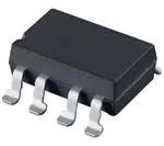
SMD
• Low power consumption
• SMD lead available on tape and reel
1
2
3
• Compliant to RoHS Directive 2002/95/EC and in
accordance to WEEE 2002/96/EC
4
i179034_2
APPLICATIONS
• General telecom switching
DESCRIPTION
- On/off hook control
The LH1512 relays contain normally open and normally
closed switches that can be used independently as a
1 form A and 1 form B relay, or when used together, as a
1 form C relay. The relays are constructed as a mult.-chip
hybrid device. Actuation control is via an infrared LED. The
output switch is a combination of a photodiode array with
MOSFET switches and control circuity.
- Ring delay
- Dial pulse
- Ground start
- Ground fault protection
• Instrumentation
• Industrial controls
AGENCY APPROVALS
UL1577: file no. E52744 system code H, double protection
CSA:
certification no. 093751
DIN EN: 60747-5-2 (VDE 0884)/60747-5-5 (pending),
available with option 1
FIMKO: 25419
ORDERING INFORMATION
L
H
1
5
PART NUMBER
1
2
B
#
ELECTR.
VARIATION
PACKAGE
#
PACKAGE
CONFIG.
T
TAPE AND
REEL
7.62 mm
SMD
> 0.1 mm
UL, CSA, FIMKO
SMD-8, tubes
LH1512BAC
SMD-8, tape and reel
LH1512BACTR
DIP-8, tubes
Rev. 1.6, 07-Jul-11
DIP
R
LH1512BB
1
Document Number: 83812
For technical questions, contact: optocoupleranswers@vishay.com
THIS DOCUMENT IS SUBJECT TO CHANGE WITHOUT NOTICE. THE PRODUCTS DESCRIBED HEREIN AND THIS DOCUMENT
ARE SUBJECT TO SPECIFIC DISCLAIMERS, SET FORTH AT www.vishay.com/doc?91000
�LH1512BAC, LH1512BACTR, LH1512BB
www.vishay.com
Vishay Semiconductors
ABSOLUTE MAXIMUM RATINGS (Tamb = 25 °C, unless otherwise specified)
PARAMETER
TEST CONDITION
SYMBOL
VALUE
UNIT
INPUT
LED continuous forward current
IF
50
mA
LED reverse voltage
IR 10 μA
VR
5
V
OUTPUT
DC or peak AC load voltage
IL 50 μA
VL
200
V
Continuous DC load current
IL
200
mA
(form C operation)
(2)
Peak load current, form A
t = 100 ms
IP
Peak load current (single shot), form B
IP
400
mA
SSR
- 40 to + 85
°C
Ambient operating temperature range
Tamb
Storage temperature range
Tstg
- 40 to + 125
°C
Pin soldering temperature (3)
t = 10 s max.
Tsld
260
°C
VISO
3750
VRMS
Input to output isolation test voltage
t = 1 s, IISO = 10 μA max.
Pole-to-pole isolation voltage (S1 to S2) (1)
1600
V
(dry air, dust free, at sea level)
Output power dissipation (continuous)
Pdiss
600
mW
Notes
• Stresses in excess of the absolute maximum ratings can cause permanent damage to the device. Functional operation of the device is not
implied at these or any other conditions in excess of those given in the operational sections of this document. Exposure to absolute
maximum ratings for extended periods of the time can adversely affect reliability.
(1) Breakdown occurs between the output pins external to the package.
(2) Refer to current limit performance application note for a discussion on relay operation during transient currents.
(3) Refer to reflow profile for soldering conditions for surface mounted devices (SMD). Refer to wave profile for soldering conditions for through
hole devices (DIP).
ELECTRICAL CHARACTERISTICS (Tamb = 25 °C, unless otherwise specified)
PARAMETER
TEST CONDITION
SYMBOL
MIN.
TYP.
MAX.
UNIT
0.6
2
mA
INPUT
LED forward current switch turn-on (NO)
IL = 100 mA, t = 10 ms
IFon
LED forward current switch turn-off (NO)
VL = ± 150 V
IFoff
0.2
0.5
LED forward current switch turn-on (NC)
IL = 100 mA, t = 10 ms
IFon
0.2
0.9
LED forward current switch turn-off (NC)
VL = ± 150 V
IFoff
IF = 10 mA
VF
LED forward voltage
mA
mA
1
2
mA
1.15
1.26
1.45
V
10
15
0.35
5000
OUTPUT
On-resistance: (NO, NC)
Off-resistance: (NO)
Off-resistance: (NC)
IF = 5 mA (NO), IF = 0 (NC), IL = 50 mA (NC)
RON
IF = 0 mA, VL = ± 100 V
ROFF
G
IF = 5 mA, VL = ± 100 V
ROFF
0.1
1.4
IF = 5 mA, t = 5 ms, VL = ± 5 V
ILMT
270
360
460
mA
Off-state leakage current: (NO)
IF = 0 mA, VL = ± 100 V
IO
0.02
1000
nA
Off-state leakage current: (NC)
IF = 5 mA, VL = ± 100 V
IO
0.07
1
μA
IF = 0 mA (NO), IF = 5 mA, VL = ± 200 V
IO
1
μA
Output capacitance: (NO)
IF = 0 mA, VL = 50 V
CO
60
pF
Output capacitance: (NC)
IF = 5 mA, VL = 50 V
CO
60
pF
VISO = 1 V
CIO
3
pF
Current limit: (NO)
Off-state leakage current: (NO, NC)
G
TRANSFER
Capacitance (input to output)
Note
• Minimum and maximum values are testing requirements. Typical values are characteristics of the device and are the result of engineering
evaluations. Typical values are for information only and are not part of the testing requirements.
SWITCHING CHARACTERISTICS (Tamb = 25 °C, unless otherwise specified)
PARAMETER
TEST CONDITION
SYMBOL
TYP.
MAX.
UNIT
Turn-on time (NO)
IF = 10 mA, IL = 50 mA
ton
1.4
3
ms
Turn-on time (NC)
IF = 10 mA, IL = 50 mA
ton
1.2
3
ms
Turn-off time (NO)
IF = 10 mA, IL = 50 mA
toff
0.7
3
ms
Turn-off time (NC)
IF = 10 mA, IL = 50 mA
toff
2
3
ms
Rev. 1.6, 07-Jul-11
2
MIN.
Document Number: 83812
For technical questions, contact: optocoupleranswers@vishay.com
THIS DOCUMENT IS SUBJECT TO CHANGE WITHOUT NOTICE. THE PRODUCTS DESCRIBED HEREIN AND THIS DOCUMENT
ARE SUBJECT TO SPECIFIC DISCLAIMERS, SET FORTH AT www.vishay.com/doc?91000
�LH1512BAC, LH1512BACTR, LH1512BB
www.vishay.com
Vishay Semiconductors
150
0.06
120
0.05
Leakage (µA)
Load Current (mA)
TYPICAL CHARACTERISTICS (Tamb = 25 °C, unless otherwise specified)
90
50
30
0
- 40
0.02
0
- 20
0
20
40
60
80
250
Load Current (mA)
250
200
20 mA
10 mA
5 mA
0
- 40 - 20
0
20
40
60
100
150
100
0
20
40
80 100 120
60
Temperature (°C)
ilh1512bb_04
Fig. 5 - Form B Typical Load Current vs. Temperature
Fig. 2 - Form A Typical Load Current vs. Temperature
200
1.8
LED Forward Voltage Drop (V)
150
100
50
0
- 50
- 100
- 150
-1
- 0.5
0
0.5
1
1.6
1.4
Load Voltage (V)
50 mA
30 mA
20 mA
10 mA
5 mA
1.2
1
0.8
- 40 - 20
1.5
ilh1512bb_06
0
20
40
60
80 100 120
Temperature (°C)
Fig. 6 - Typical LED Forward Voltage Drop vs. Temperature
Fig. 3 - Form A Typical Load Current vs. Load Voltage
Rev. 1.6, 07-Jul-11
80
200
0
- 40 - 20
80 100 120
Temperature (°C)
ilh1512bb_01
ilh1512bb_02
60
50
50
- 200
- 1.5
40
Fig. 4 - Typical Leakage vs. Temperature
(Measured across Pin 5 and 6 or 7 and 8)
300
100
20
Temperature (°C)
ilh1512bb_03
300
150
0
- 40 - 20
Ambient Temperature (°C)
Fig. 1 - Recommended Operating Conditions
Load Current (mA)
0.03
0.01
ilh1521bb_00
Load Current (mA)
0.04
3
Document Number: 83812
For technical questions, contact: optocoupleranswers@vishay.com
THIS DOCUMENT IS SUBJECT TO CHANGE WITHOUT NOTICE. THE PRODUCTS DESCRIBED HEREIN AND THIS DOCUMENT
ARE SUBJECT TO SPECIFIC DISCLAIMERS, SET FORTH AT www.vishay.com/doc?91000
�LH1512BAC, LH1512BACTR, LH1512BB
Vishay Semiconductors
285
335
280
330
Blocking Voltage (VRMS)
Blocking Voltage (VRMS)
www.vishay.com
275
270
265
260
325
320
315
310
305
300
255
- 40 - 20
ilh1512bb_07
0
20
40
60
80
295
- 40 - 20
100
Temperature (°C)
20
40
60
80 100
Fig. 10 - Form B Typical Blocking Voltage vs. Temperature
Fig. 7 - Form A Typical Blocking Voltage vs. Temperature
2
0.2
1.8
5 mA
1.6
0.15
1.4
10 mA
Turn-on (ms)
Turn-on (ms)
0
Temperature (°C)
ilh1512bb_10
1.2
1
0.8
20 mA
0.6
0.1
5 mA
0.05
0.4
0.2
0
- 40 - 20
ilh1512bb_08
0
20
40
60
80
0
- 40
100
Temperature (°C)
3.5
0.3
3
0.25
2.5
Turn-off (ms)
Turn-off (ms)
0.35
0.2
0.15
5 mA
0.5
ilh1512bb_09
60
80
0
- 40 - 20
100
ilh1512bb_12
Temperature (°C)
80 100
5 mA
10 mA
0
20
40
60
80
100
Temperature (°C)
Fig. 12 - Form B Typical Turn-Off vs. Temperature
Fig. 9 - Form A Typical Turn-Off vs. Temperature
Rev. 1.6, 07-Jul-11
60
20 mA
0.05
40
40
1.5
1
20
20
Temperature (°C)
2
0.1
0
0
Fig. 11 - Form B Typical Turn-On vs. Temperature
Fig. 8 - Form A Typical Turn-On vs. Temperature
0
- 40 - 20
- 20
ilh1512bb_11
4
Document Number: 83812
For technical questions, contact: optocoupleranswers@vishay.com
THIS DOCUMENT IS SUBJECT TO CHANGE WITHOUT NOTICE. THE PRODUCTS DESCRIBED HEREIN AND THIS DOCUMENT
ARE SUBJECT TO SPECIFIC DISCLAIMERS, SET FORTH AT www.vishay.com/doc?91000
�LH1512BAC, LH1512BACTR, LH1512BB
www.vishay.com
Vishay Semiconductors
0.0785
0.8
0.7
0.0780
Turn-on (ms)
Turn-on (ms)
0.6
0.5
0.4
0.3
0.2
0.0775
0.0770
0.0765
0.1
0.0760
0
0
5
0
10 15 20 25 30 35 40 45 50
LED Forward Current (mA)
LED Forward Current (mA)
ilh1512bb_13
5 10 20 30 40 50 60 70 80 90
ilh1512bb_16
Fig. 16 - Form B Typical Turn-On vs. LED Forward Current
Fig. 13 - Form A Typical Turn-On vs. LED Forward Current
2.5
0.35
0.3
2
Turn-off (ms)
Turn-off (ms)
0.25
0.2
0.15
1.5
1
0.1
0.5
0.05
0
0
0
0
5 10 15 20 25 30 35 40 45 50
5 10 15 20 25 30 35 40 45 50
LED Forward Current (mA)
ilh1512bb_14
LED Forward Current (mA)
ilh1512bb_17
Fig. 17 - Form B Typical Turn-Off vs. LED Forward Current
9
9
8
8
7
7
On-resistance (Ω)
On-resistance (Ω)
Fig. 14 - Form A Typical Turn-Off vs. LED Forward Current
6
5
4
3
2
6
5
4
3
2
1
1
0
- 40 - 20
0
- 40 - 20
ilh1512bb_15
0
20
40
60
80
100
Temperature (°C)
ilh1512bb_18
20
40
60
80
100
Temperature (°C)
Fig. 18 - Form B Typical On-Resistance vs. Temperature
Fig. 15 - Form A Typical On-Resistance vs. Temperature
Rev. 1.6, 07-Jul-11
0
5
Document Number: 83812
For technical questions, contact: optocoupleranswers@vishay.com
THIS DOCUMENT IS SUBJECT TO CHANGE WITHOUT NOTICE. THE PRODUCTS DESCRIBED HEREIN AND THIS DOCUMENT
ARE SUBJECT TO SPECIFIC DISCLAIMERS, SET FORTH AT www.vishay.com/doc?91000
�LH1512BAC, LH1512BACTR, LH1512BB
Vishay Semiconductors
3
3
2.5
2.5
LED Current (mA)
LED Current (mA)
www.vishay.com
2
1.5
1
0.5
2
1.5
1
0.5
0
0
- 40 - 20
ilh1512bb_19
0
20
40
60
80
100
- 40 - 20
Temperature (°C)
ilh1512bb_22
0
20
40
60
80
100
Temperature (°C)
Fig. 22 - Form B Typical IF for Switch Dropout vs. Temperature
Fig. 19 - Form A Typical IF for Switch Operation vs. Temperature
3
LED Current (mA)
2.5
2
1.5
1
0.5
0
- 40 - 20
0
20
40
60
80
100
Temperature (°C)
ilh1512bb_20
Fig. 20 - Form A Typical IF for Switch Dropout vs. Temperature
3
LED Current (mA)
2.5
2
1.5
1
0.5
0
- 40 - 20
ilh1512bb_21
0
20
40
60
80
100
Temperature (°C)
Fig. 21 - Form B Typical IF for Switch Operation vs. Temperature
Rev. 1.6, 07-Jul-11
6
Document Number: 83812
For technical questions, contact: optocoupleranswers@vishay.com
THIS DOCUMENT IS SUBJECT TO CHANGE WITHOUT NOTICE. THE PRODUCTS DESCRIBED HEREIN AND THIS DOCUMENT
ARE SUBJECT TO SPECIFIC DISCLAIMERS, SET FORTH AT www.vishay.com/doc?91000
�LH1512BAC, LH1512BACTR, LH1512BB
www.vishay.com
Vishay Semiconductors
PACKAGE DIMENSIONS in millimeters
DIP
9.65
6 to 0.8 dia.
2.54
2.54
6.35
9.14
6.35
7.62
0.46
7.62
8.08
7.62
3.3
7.24 typ.
ISO method A
9.14 typ.
i178017
SMD
9.65
2.54
2.54
6.35
8.31
9.53
1.9
0.46
1.5
8.08
7.62
4.45
3.3
ISO method A
0.25 typ.
0.64 typ.
i178018
PACKAGE MARKING (example)
LH1512
V YWW H 68
Note
• Tape and reel suffix (TR) is not part of the package marking.
Rev. 1.6, 07-Jul-11
7
Document Number: 83812
For technical questions, contact: optocoupleranswers@vishay.com
THIS DOCUMENT IS SUBJECT TO CHANGE WITHOUT NOTICE. THE PRODUCTS DESCRIBED HEREIN AND THIS DOCUMENT
ARE SUBJECT TO SPECIFIC DISCLAIMERS, SET FORTH AT www.vishay.com/doc?91000
�Footprint and Schematic Information
www.vishay.com
Vishay Semiconductors
Footprint and Schematic Information
for LH1512BAC, LH1512BACTR, LH1512BB
The footprint and schematic symbols for the following parts can be accessed using the associated links. They are available in
Eagle, Altium, KiCad, OrCAD / Allegro, Pulsonix, and PADS.
Note that the 3D models for these parts can be found on the Vishay product page.
PART NUMBER
FOOTPRINT / SCHEMATIC
LH1512BAC
LH1512BACTR
www.snapeda.com/parts/LH1512BAC/Vishay/view-part
www.snapeda.com/parts/LH1512BACTR/Vishay/view-part
LH1512BB
www.snapeda.com/parts/LH1512BB/Vishay/view-part
For technical issues and product support, please contact optocoupleranswers@vishay.com.
DIP
SMD
i179034_2
Rev. 1.0, 09-May-17
Document Number: 84475
1
For technical questions, contact: optocoupleranswers@vishay.com
THIS DOCUMENT IS SUBJECT TO CHANGE WITHOUT NOTICE. THE PRODUCTS DESCRIBED HEREIN AND THIS DOCUMENT
ARE SUBJECT TO SPECIFIC DISCLAIMERS, SET FORTH AT www.vishay.com/doc?91000
�Legal Disclaimer Notice
www.vishay.com
Vishay
Disclaimer
ALL PRODUCT, PRODUCT SPECIFICATIONS AND DATA ARE SUBJECT TO CHANGE WITHOUT NOTICE TO IMPROVE
RELIABILITY, FUNCTION OR DESIGN OR OTHERWISE.
Vishay Intertechnology, Inc., its affiliates, agents, and employees, and all persons acting on its or their behalf (collectively,
“Vishay”), disclaim any and all liability for any errors, inaccuracies or incompleteness contained in any datasheet or in any other
disclosure relating to any product.
Vishay makes no warranty, representation or guarantee regarding the suitability of the products for any particular purpose or
the continuing production of any product. To the maximum extent permitted by applicable law, Vishay disclaims (i) any and all
liability arising out of the application or use of any product, (ii) any and all liability, including without limitation special,
consequential or incidental damages, and (iii) any and all implied warranties, including warranties of fitness for particular
purpose, non-infringement and merchantability.
Statements regarding the suitability of products for certain types of applications are based on Vishay’s knowledge of
typical requirements that are often placed on Vishay products in generic applications. Such statements are not binding
statements about the suitability of products for a particular application. It is the customer’s responsibility to validate that a
particular product with the properties described in the product specification is suitable for use in a particular application.
Parameters provided in datasheets and / or specifications may vary in different applications and performance may vary over
time. All operating parameters, including typical parameters, must be validated for each customer application by the customer’s
technical experts. Product specifications do not expand or otherwise modify Vishay’s terms and conditions of purchase,
including but not limited to the warranty expressed therein.
Except as expressly indicated in writing, Vishay products are not designed for use in medical, life-saving, or life-sustaining
applications or for any other application in which the failure of the Vishay product could result in personal injury or death.
Customers using or selling Vishay products not expressly indicated for use in such applications do so at their own risk.
Please contact authorized Vishay personnel to obtain written terms and conditions regarding products designed for
such applications.
No license, express or implied, by estoppel or otherwise, to any intellectual property rights is granted by this document
or by any conduct of Vishay. Product names and markings noted herein may be trademarks of their respective owners.
© 2019 VISHAY INTERTECHNOLOGY, INC. ALL RIGHTS RESERVED
Revision: 01-Jan-2019
1
Document Number: 91000
�


 工商网监
湘ICP备2023018690号
工商网监
湘ICP备2023018690号


