LSR37
Vishay BCcomponents
High Voltage Surge Metal Glaze Leaded Resistor
FEATURES
• High pulse-loading (10 kV as specified)
capability (flashes)
• Good replacement for carbon-composite
resistors
• Lead (Pb)-free solder contacts
• Pure Tin plating provides compatibility with lead (Pb)-free
and lead containing soldering processes
A metal glazed film is deposited on a high grade ceramic
body. After that caps are applied to the rods and tinned
electrolytic copper wires are welded to these end caps.
The resistors are coated with a light-blue lacquer which
provides electrical, mechanical and climatic protection.
The encapsulation is resistant to all cleaning solvents
according to IEC 60068-2-45.
• Compliant to RoHS directive 2002/95/EC
APPLICATIONS
• Application in overload and high voltage pulse hazard
circuits (TV-sets, monitors), high power electronic ballasts
TECHNICAL SPECIFICATIONS
DESCRIPTION
VALUE
220 Ω to 910 Ω
Resistance Range (1)
Resistance Tolerance and Series
1 kΩ to 10 kΩ
± 10 %; ± 20 %; E12 series
Rated Dissipation, P70
0.5 W
Thermal Resistance, Rth
120 K/W
Temperature Coefficient
Voltage Coefficient
Maximum Permissible Voltage Umax.
0 ppm/K to + 600 ppm/K
- 600 ppm/K to + 200 ppm/K
0 to + 350 ppm/V
± 50 ppm/V
Pn x R
V=
Dielectric Withstanding Voltage of the Insulation for 1 Min
Basic Specifications
700 V
IEC 60115-1
Climatic Category (IEC 60068-1)
55/155/56
Stability After:
Load (1000 h, P70)
ΔR max.: ± (3.0 % R + 0.10 Ω)
Long Term Damp Heat Test (56 Days)
ΔR max.: ± (3.0 % R + 0.10 Ω)
Soldering (10 s, 260 °C)
ΔR max.: ± (1.0 % R + 0.10 Ω)
High Voltage Test for R-Value > 3.3 kΩ, 10 kV; 1 nF; 50 x 12/Min
ΔR/R max.: ± 20 %
(typical value ± 10 %)
ESD Contact Discharge 12 kV; 100 Pulses
ΔR/R max.: ± 20 %
(typical value: ± 10 %)
Note
(1) R values below 220 Ω are available on request
www.vishay.com
190
For technical questions, contact: filmresistorsleaded@vishay.com
Document Number: 28735
Revision: 19-Oct-09
�LSR37
High Voltage Surge Metal Glaze
Leaded Resistor
Vishay BCcomponents
PART NUMBER
PART NUMBER: LSR3700001002KA100
L
S
R
3
7
0
0
0
0
1
0
0
2
K
A
1
0
0
MODEL/SIZE
VARIANT
TCR/MATERIAL
VALUE
TOLERANCE
PACKAGING (1)
SPECIAL
LSR3700
0 = Neutral
0 = Standard
3 digit value
1 digit multiplier
MULTIPLIER
9 = *10-1
0 = *100
1 = *101
2 = *102
K = ± 10 %
M = ± 20 %
A1
R5
The 2 digits
are used for all
special parts.
Z = Value overflow
(Special)
00 = Standard
PRODUCT DESCRIPTION: LSR37 10 % A1 10K
LSR37
10 %
A1
10K
MODEL/SIZE
TOLERANCE
PACKAGING (1)
RESISTANCE VALUE
LSR37
± 10 %
± 20 %
A1
R5
220R = 220 Ω
1K2 = 1.2 kΩ
Notes
(1) Please refer to table PACKAGING
• The PART NUMBER is shown to facilitate the introduction of a unified part numbering system for ordering products
PACKAGING
AMMO PACK
MODEL
REEL
TAPING
LSR37
Axial, 52 mm
PIECES
CODE
PIECES
CODE
1000
A1
5000
R5
DIMENSIONS
L1
Ø d
Ø D
L2
Outline
DIMENSIONS - resistor type and relevant physical dimensions
TYPE
Ø Dmax.
L1 max.
L2 max.
Ød
LSR37
4.0
9.0
10.0
0.7 ± 0.03
Document Number: 28735
Revision: 19-Oct-09
For technical questions, contact: filmresistorsleaded@vishay.com
www.vishay.com
191
�LSR37
High Voltage Surge Metal Glaze
Leaded Resistor
Vishay BCcomponents
MARKING
MASS PER UNIT
TYPE
MASS
(mg)
LSR37
457
The nominal resistance and tolerance are marked on the
resistor using colored bands in accordance with IEC 60062,
marking codes for resistors and capacitors.
Three bands are used for 20 % tolerance with no indication
for the tolerance. Four bands are used for 10 % tolerance.
Grey is used instead of silver for 10 % because metal
particles in the lacquer could affect high-voltage properties.
OUTLINES
The length of the body (L1) is measured by inserting the
leads into holes of two identical gauge plates and moving
these plates parallel to each other until the resistor body is
clamped without deformation (IEC 60294).
FUNCTIONAL PERFORMANCE
PRODUCT CHARACTERIZATION
Standard values of rated resistance (nominal resistance) are taken from the E12 series with a tolerance of 10 % or 20 %. The
values of the E12 series are in accordance with IEC 60063.
The limiting voltage DC is not applicable, because the maximum rated voltage for the maximum Rn-value of 10 kΩ at Pn = 0.5 W
is only 70.7 V.
LIMITING VALUES
TYPE
LSR37
MAXIMUM PERMISSIBLE VOLTAGE Umax. (1)
(V)
V=
RATED DISSIPATION, P70
(W)
Pn x R
0.5
Notes
(1) The maximum voltage that may be continuously applied to the resistor element, see IEC 60115-1
• The maximum permissible hot-spot temperature is 155 °C
www.vishay.com
192
For technical questions, contact: filmresistorsleaded@vishay.com
Document Number: 28735
Revision: 19-Oct-09
�LSR37
High Voltage Surge Metal Glaze
Leaded Resistor
Vishay BCcomponents
Pmax.
(% P rated)
100
50
The power that the resistor can dissipate depends on the operating
temperature.
0
- 55
0
50
70
100
155
T amb (°C)
Maximum dissipation (Pmax.) in percentage of rated power as a
function of the ambient temperature (Tamb).
Derating
104
Pˆmax.
(W)
103
102
10
1
10- 6
10- 5
10- 4
10- 3
10- 2
10- 1
t i (s)
1
Pulse on a regular basis; maximum permissible peak pulse power Pmax. as a function of pulse duration (ti) for single pulse condition
Pulse Loading Capability
The resistors with straight leads are suitable for processing on automatic insersion equipment and cutting and bending machines.
the minimum pitch for this type is 6e (15 mm). For temperature rise at soldering place see figures below.
80
50
∆T
(K)
∆T
(K)
5 mm
40
60
10 mm
30
15 mm
40
20
20
0
10
0
0
0.4
0.8
P (W)
1.2
Hot-spot temperature rise (ΔT) as a function of dissipated power
0
0.4
0.8
P (W)
1.2
Temperature rise (ΔT) at the lead end (soldering point) as a function
of dissipated power at various lead lengths after mounting
Application Information
Document Number: 28735
Revision: 19-Oct-09
For technical questions, contact: filmresistorsleaded@vishay.com
www.vishay.com
193
�LSR37
High Voltage Surge Metal Glaze
Leaded Resistor
Vishay BCcomponents
TESTS AND REQUIREMENTS
Essentially all tests are carried out in accordance with
the IEC 60115-1 specifications, category LCT/UCT/56 (rated
temperature range: Lower Category Temperature, Upper
Category Temperature; damp heat, long term, 56 days).
The tests are carried out in accordance with IEC 60068-2-xx
test method under standard atmospheric conditions
according to IEC 60068-1, 5.3.
In the Test Procedures and Requirements table the tests and
requirements are listed with reference to the relevant
clauses of IEC 60115-1 and IEC 60068-2-xx test methods. A
short description of the test procedure is also given. In some
instances deviations from the IEC recommendations were
necessary for our method of specifying.
All soldering tests are performed with mildly activated flux.
TEST PROCEDURES AND REQUIREMENTS
IEC
60068-2-xx
TEST
METHOD
TEST
21 (U)
Robustness of terminations:
4.16.2
21 (Ua1)
4.16.3
IEC
60115-1
CLAUSE
PROCEDURE
REQUIREMENTS
Tensile all samples
Ø 0.7 mm; load 10 N; 10 s
Number of failures < 10 x 10-6
21 (Ub)
Bending half number
of samples
Ø 0.7 mm; load 5 N; 4 x 90°
Number of failures < 10 x 10-6
4.16.4
21 (Uc)
Torsion other half
of samples
3 x 360° in opposite directions
No damage
ΔR max.: ± (1.0 % R + 0.10 Ω)
4.17
20 (Ta)
Solderability
2 s; 235 °C: Solder bath method;
SnPb40
3 s; 245 °C: Solder bath method;
SnAg3Cu0.5
Good tinning; no damage
4.18
20 (Tb)
Resistance to
soldering heat
Thermal shock: 10 s; 260 °C;
3 mm from body
ΔR max.: ± (1.0 % R + 0.10 Ω)
4.19
14 (Na)
Rapid change of temperature
30 min at - 55 °C and
30 min at + 155 °C; 5 cycles
ΔR max.: ± (1.0 % R + 0.10 Ω)
4.20
29 (Eb)
Bump
3 x 1500 bumps in 3 directions; 40 g
No damage
ΔR max.: ± (1.0 % R + 0.10 Ω)
4.22
6 (Fc)
Vibration
Frequency 10 Hz to 500 Hz; displacement
1.5 mm or acceleration 10 g; 3 directions;
total 6 h (3 x 2 h)
No damage
ΔR max.: ± (1.0 % R + 0.10 Ω)
4.16
4.23
Climatic sequence:
2 (Ba)
Dry heat
16 h; 155 °C
4.23.3
30 (Db)
Damp heat (accelerated) 1st
cycle
24 h; 55 °C; 90 % to 100 % RH
4.23.4
1 (Aa)
Cold
2 h; - 55 °C
4.23.5
13 (M)
Low air pressure
2 h; 8.5 kPa; 15 °C to 35 °C
4.23.6
30 (Db)
Damp heat (accelerated)
remaining cycles
5 days; 55 °C; 95 % to 100 % RH
4.24.2
78 (Cab)
Damp heat
(steady state)
56 days; 40 °C; 90 % to 95 % RH;
dissipation 0.01 P70;
limiting voltage Umax. 100 VDC
ΔR max.: ± (3.0 % R + 0.10 Ω)
Endurance
1000 h at 70 °C; P70 or Umax.
ΔR max.: ± (3.0 % R + 0.10 Ω)
4.23.2
4.25.1
Rins min.: 103 MΩ
ΔR max.: ± (3.0 % R + 0.10 Ω)
220 Ω to 910 Ω
0 to + 600 ppm/K
1 kΩ to 10 kΩ
- 600 to + 200 ppm/K
4.8
Temperature coefficient
4.7
Voltage proof on insulation
URMS = 700 V during 1 min;
V-block method
No breakdown
Insulation resistance
U = 500 VDC during 1 min;
V-block method
Rins min.: 104 MΩ
4.6.1.1
www.vishay.com
194
For technical questions, contact: filmresistorsleaded@vishay.com
Document Number: 28735
Revision: 19-Oct-09
�LSR37
High Voltage Surge Metal Glaze
Leaded Resistor
Vishay BCcomponents
TEST PROCEDURES AND REQUIREMENTS
IEC
60115-1
CLAUSE
IEC
60068-2-xx
TEST
METHOD
4.13
TEST
PROCEDURE
REQUIREMENTS
Short time overload
Room temperature; dissipation 6.25 x P70;
10 cycles;
5 s ON and 45 s OFF
ΔR max.: ± (2.5 % R + 0.10 Ω)
High voltage pulse 10 kV;
1 nF; 50 x 12/min
For Rn > 3.3 kΩ
ΔR/R max.: ± 20 %
(typical value ± 10 %)
12 kV ESD test; 100 pulses
ESD contact discharge
ΔR/R max.: ± 20 %
(typical value: ± 10 %)
4.26
Active flammability
“cheese-cloth test”
4.35
Passive flammability
“needle-flame test”
Steps of: 5/10/16/25/40 x P70 duration
5 min
Application of test flame for 20 s
No flaming of gauze cylinder
No ignition of product
no ignition of under-layer
burning time less than 30 s
12NC INFORMATION FOR HISTORICAL CODING REFERENCE
• The resistors have a 12-digit numeric code starting with
2322 245
Last Digit of 12NC Indicating Resistance Decade
RESISTANCE DECADE
LAST DIGIT
47 Ω to 82 Ω
9
• The remaining digits indicate the resistance value:
100 Ω to 820 Ω
1
- The first 2 digits indicate the resistance value
1 kΩ to 9.1 kΩ
2
- The last digit indicates the resistance decade
10 kΩ
3
• The subsequent 2 digits indicate the resistor type and
packing
12NC Example
The 12NC for a LSR37, resistor value 1.5 kΩ, 10 %
tolerance, supplied on a bandolier of 1000 units in
ammopack, is: 2322 245 12152.
12NC - Resistor type and packaging
2322 245 .....
TYPE
TOLERANCE
(%)
1000 UNITS
IN AMMOPACK
5000 UNITS
ON REEL
± 10
12...
22...
± 20
11...
21...
LSR37
Document Number: 28735
Revision: 19-Oct-09
For technical questions, contact: filmresistorsleaded@vishay.com
www.vishay.com
195
�Legal Disclaimer Notice
Vishay
Disclaimer
All product specifications and data are subject to change without notice.
Vishay Intertechnology, Inc., its affiliates, agents, and employees, and all persons acting on its or their behalf
(collectively, “Vishay”), disclaim any and all liability for any errors, inaccuracies or incompleteness contained herein
or in any other disclosure relating to any product.
Vishay disclaims any and all liability arising out of the use or application of any product described herein or of any
information provided herein to the maximum extent permitted by law. The product specifications do not expand or
otherwise modify Vishay’s terms and conditions of purchase, including but not limited to the warranty expressed
therein, which apply to these products.
No license, express or implied, by estoppel or otherwise, to any intellectual property rights is granted by this
document or by any conduct of Vishay.
The products shown herein are not designed for use in medical, life-saving, or life-sustaining applications unless
otherwise expressly indicated. Customers using or selling Vishay products not expressly indicated for use in such
applications do so entirely at their own risk and agree to fully indemnify Vishay for any damages arising or resulting
from such use or sale. Please contact authorized Vishay personnel to obtain written terms and conditions regarding
products designed for such applications.
Product names and markings noted herein may be trademarks of their respective owners.
Document Number: 91000
Revision: 18-Jul-08
www.vishay.com
1
�
很抱歉,暂时无法提供与“LSR3700Z02700KR500”相匹配的价格&库存,您可以联系我们找货
免费人工找货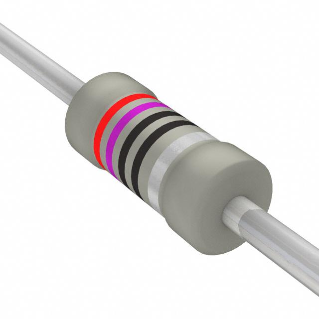


 工商网监
湘ICP备2023018690号
工商网监
湘ICP备2023018690号
