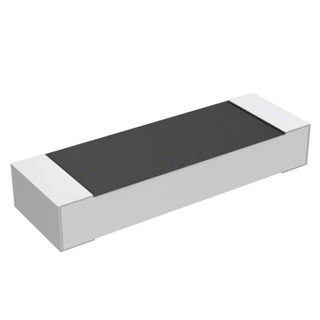
RCWPM Jumper (Military M32159)
Vishay Dale
Thick Film Chip Resistors, Zero Ohm Jumper, Military/Established
Reliability MIL-PRF-32159 Qualified, Type RCZ
FEATURES
• Fully conforms to the requirements of
MIL-PRF-32159
• Established reliability - verified failure rate; M level
• Operating temperature range is - 55 °C to + 150 °C
• 100 % group A screening per MIL-PRF-32159
• Termination style B - tin/lead wraparound over nickel
barrier
• For MIL-PRF-55342 chip resistors, see Vishay Dale’s
RCWPM (Military M/D55342) datasheet
• Halogen-free according to IEC 61249-2-21 definition
STANDARD ELECTRICAL SPECIFICATIONS
VISHAY DALE
MODEL
POWER RATING
P70 °C
W
CURRENT
RATING
A
MAXIMUM
RESISTANCE
MIL-PRF-32159
STYLE
MIL SPEC.
SHEET
TERM.
CASE
SIZE
RCWPM-0502-99
RCZ0502
01
B
0502
0.05
1.3
30m
RCWPM-550-99
RCZ0505
02
B
0505
0.100
2.2
20m
RCWPM-5100-99
RCZ1005
03
B
1005
0.20
2.8
25m
RCWPM-5150-99
RCZ1505
04
B
1505
0.15
2.1
35m
RCWPM-7225-99
RCZ2208
05
B
2208
0.225
2.5
35m
RCWPM-575-99
RCZ0705
06
B
0705 (1)
0.15
2.7
20m
RCWPM-1206-99
RCZ1206
07
B
1206
0.25
3.2
25m
RCWPM-2010-99
RCZ2010
08
B
2010
0.80
5.7
25m
RCWPM-2512-99
RCZ2512
09
B
2512
1.0
6.3
25m
RCWPM-1100-99
RCZ1010
10
B
1010
0.50
5.0
20m
RCWPM-0402-99
RCZ0402
11
B
0402
0.04
1.2
30m
RCWPM-0603-99
RCZ0603
12
B
0603
0.07
1.5
30m
RCWPM-0302-99
RCZ0302
13
B
0302
0.035
1.1
30m
Note
• DSCC has created a series of drawings to support the need for zero ohm jumper product. Vishay Dale is listed as a resource on these
drawings as follows:
VISHAY DALE
MODEL
TERM.
MAXIMUM
RESISTANCE
m
MAX. CURRENT
RATING
A
MAXIMUM WORKING
VOLTAGE
V
03011
RCWPM0201..99
B
50
0.5
30
03012
RCWPM0302..99
B
20
1.1
15
03014
RCWPM0402..99
B
25
1.2
30
88032
RCWPM0502..99
B
20
1.3
40
03013
RCWPM0603..99
B
25
1.5
50
03002
RCWPM0550..99
B
25
2.2
40
90048
RCWPM0575..99
B
20
2.7
50
90049
RCWPM5100..99
B
30
2.8
75
94011
RCWPM1206..99
B
20
3.2
100
90092
RCWPM5150..99
B
40
2.1
125
87011
RCWPM1100..99
B
20
5.0
75
90047
RCWPM7225..99
B
40
2.5
175
03015
RCWPM2010..99
B
40
5.7
150
03016
RCWPM2512..99
B
40
6.3
200
DSCC
DRAWING
NUMBER
These drawings can be viewed at: www.dscc.dla.mil/Programs/MilSpec/ListDwgs.asp?DocType=DSCCdwg.
Note
(1) MIL case size 0705 and EIA case size 0805 are dimensionally the same.
Document Number: 31028
Revision: 28-Oct-10
For technical questions, contact: ff2aresistors@vishay.com
www.vishay.com
1
�RCWPM Jumper (Military M32159)
Vishay Dale Thick Film Chip Resistors, Zero Ohm Jumper, Military/Established
Reliability MIL-PRF-32159 Qualified, Type RCZ
GLOBAL PART NUMBER INFORMATION
Part Number (MIL-PRF-32159): M32159B02MWB (preferred part number format)
M
3
2
1
5
9
B
0
2
M
W
B
MIL STYLE
TERMINATION
STYLE
SPEC SHEET
FAILURE RATE
PACKAGING
M32159
B = Pre-tinned
nickel barrier,
wraparound
(see Standard
Electrical
Specifications
table)
C = Non-ER
M = Military grade,
high reliability
TP = Tin/lead, T/R (full)
S3 = Tin/lead, T/R (1000 pieces)
UL = Tin/lead, T/R, single lot date code
WB = Tin/lead, tray
WL = Tin/lead, tray, single lot date code
S2 = Tin/lead, T/R (500 pieces)
S6 = Tin/lead, T/R (300 pieces)
Part Number (DSCC Drawings): RCWPM5100WB99
R
C
W
P
GLOBAL MODEL
RCWPM0201
RCWPM0302
RCWPM0402
RCWPM0502
RCWPM0550
RCWPM0575
RCWPM0603
RCWPM1100
RCWPM1206
RCWPM2010
RCWPM2512
RCWPM5100
RCWPM5150
RCWPM7225
M
5
1
0
0
W
B
9
9
PACKAGING
SPECIAL
TP = Tin/lead, T/R (full)
S3 = Tin/lead, T/R (1000 pieces)
UL = Tin/lead, T/R, single lot date code
WB = Tin/lead, tray
WL = Tin/lead, tray, single lot date code
S2 = Tin/lead, T/R (500 pieces)
S6 = Tin/lead, T/R (300 pieces)
99 = 0 Jumper
DIMENSIONS in inches (millimeters)
D
C
B
A
VISHAY DALE
MODEL
MIL.
MIL-PRF-32159 SPEC.
STYLE
SHEET
E
A
(LENGTH)
B
(WIDTH)
C
(HEIGHT)
D
(TOP TERM)
E
(BOTTOM TERM)
RCWPM-0502-99
RCZ0502
01
0.055 ± 0.005
(1.40 ± 0.13)
0.023 ± 0.003
(0.58 ± 0.08)
0.015 ± 0.003
(0.38 ± 0.08)
0.010 ± 0.005
(0.25 ± 0.13)
0.015 ± 0.005
(0.38 ± 0.13)
RCWPM-550-99
RCZ0505
02
0.055 ± 0.005
(1.40 ± 0.13)
0.050 ± 0.005
(1.27 ± 0.13)
0.020 ± 0.005
(0.51 ± 0.13)
0.010 ± 0.005
(0.25 ± 0.13)
0.015 ± 0.005
(0.38 ± 0.13)
RCWPM-5100-99
RCZ1005
03
0.105 ± 0.005
(2.67 ± 0.13)
0.050 ± 0.005
(1.27 ± 0.13)
0.020 ± 0.005
(0.51 ± 0.13)
0.015 ± 0.005
(0.38 ± 0.13)
0.015 ± 0.005
(0.38 ± 0.13)
RCWPM-5150-99
RCZ1505
04
0.155 ± 0.005
(3.94 ± 0.13)
0.050 ± 0.005
(1.27 ± 0.13)
0.020 ± 0.005
(0.51 ± 0.13)
0.015 ± 0.005
(0.38 ± 0.13)
0.015 ± 0.005
(0.38 ± 0.13)
RCWPM-7225-99
RCZ2208
05
0.230 ± 0.005
(5.84 ± 0.13)
0.075 ± 0.005
(1.91 ± 0.13)
0.020 ± 0.005
(0.51 ± 0.13)
0.020 ± 0.005
(0.51 ± 0.13)
0.020 ± 0.005
(0.51 ± 0.13)
RCWPM-575-99
RCZ0705
06
0.080 ± 0.005
(2.03 ± 0.13)
0.050 ± 0.005
(1.27 ± 0.13)
0.020 ± 0.005
(0.51 ± 0.13)
0.016 ± 0.008
(0.41 ± 0.20)
0.015 ± 0.005
(0.38 ± 0.13)
RCWPM-1206-99
RCZ1206
07
0.125 ± 0.005
(3.18 ± 0.13)
0.063 ± 0.005
(1.60 ± 0.13)
0.020 ± 0.005
(0.51 ± 0.13)
0.015 ± 0.005
(0.38 ± 0.13)
0.015 ± 0.005
(0.38 ± 0.13)
RCWPM-2010-99
RCZ2010
08
0.197 ± 0.006
(5.00 ± 0.15)
0.098 ± 0.005
(2.49 ± 0.13)
0.020 ± 0.005
(0.51 ± 0.13)
0.020 ± 0.005
(0.51 ± 0.13)
0.020 ± 0.005
(0.51 ± 0.13)
RCWPM-2512-99
RCZ2512
09
0.250 ± 0.006
(6.35 ± 0.15)
0.124 ± 0.005
(3.15 ± 0.13)
0.020 ± 0.005
(0.51 ± 0.13)
0.020 ± 0.005
(0.51 ± 0.13)
0.020 ± 0.005
(0.51 ± 0.13)
www.vishay.com
2
For technical questions, contact: ff2aresistors@vishay.com
Document Number: 31028
Revision: 28-Oct-10
�RCWPM Jumper (Military M32159)
Thick Film Chip Resistors, Zero Ohm Jumper, Military/Established Vishay Dale
Reliability MIL-PRF-32159 Qualified, Type RCZ
DIMENSIONS in inches (millimeters)
D
C
B
A
MIL.
MIL-PRF-32159 SPEC.
STYLE
SHEET
VISHAY DALE
MODEL
E
A
(LENGTH)
B
(WIDTH)
C
(HEIGHT)
D
(TOP TERM)
E
(BOTTOM TERM)
RCWPM-1100-99
RCZ1010
10
0.105 ± 0.005
(2.67 ± 0.13)
0.100 ± 0.005
(2.54 ± 0.13)
0.020 ± 0.005
(0.51 ± 0.13)
0.015 ± 0.005
(0.38 ± 0.13)
0.015 ± 0.005
(0.38 ± 0.13)
RCWPM-0402-99
RCZ0402
11
0.039 ± 0.003
(0.99 ± 0.08)
0.020 ± 0.003
(0.51 ± 0.08)
0.013 ± 0.003
(0.33 ± 0.08)
0.010 ± 0.005
(0.25 ± 0.13)
0.010 ± 0.005
(0.25 ± 0.13)
RCWPM-0603-99
RCZ0603
12
0.063 ± 0.005
(1.60 ± 0.13)
0.032 ± 0.005
(0.81 ± 0.13)
0.018 ± 0.005
(0.46 ± 0.13)
0.012 ± 0.005
(0.30 ± 0.13)
0.015 ± 0.005
(0.38 ± 0.13)
RCWPM-0302-99
RCZ0302
13
0.034 ± 0.004
(0.86 ± 0.10)
0.021 ± 0.003
(0.53 ± 0.08)
0.013 ± 0.003
(0.33 ± 0.08)
0.007 ± 0.005
(0.18 ± 0.13)
0.008 ± 0.005
(0.20 ± 0.13)
0.024 ± 0.002
(0.61 ± 0.05)
0.012 ± 0.002
(0.30 ± 0.05)
0.009 ± 0.002
(0.23 ± 0.05)
0.006 ± 0.003
(0.15 ± 0.08)
0.006 + 0.002 - 0.004
(0.15 + 0.05 - 0.10)
RCWPM-0201-99
Rated Power in %
DERATING CURVE
120
100
80
CAGE CODE: 91637 and SH903
60
40
20
0
- 55 - 25
0
25
50
75 100 125 150 175
70 Ambient Temperature in °C
MECHANICAL SPECIFICATIONS
Resistive element
Encapsulation
Substrate
Conductive metal
Epoxy
96 % alumina
Termination
Solder-coated nickel barrier
Solder finish
Tin/lead solder alloy
Document Number: 31028
Revision: 28-Oct-10
For technical questions, contact: ff2aresistors@vishay.com
www.vishay.com
3
�Legal Disclaimer Notice
Vishay
Disclaimer
ALL PRODUCT, PRODUCT SPECIFICATIONS AND DATA ARE SUBJECT TO CHANGE WITHOUT NOTICE TO IMPROVE
RELIABILITY, FUNCTION OR DESIGN OR OTHERWISE.
Vishay Intertechnology, Inc., its affiliates, agents, and employees, and all persons acting on its or their behalf (collectively,
“Vishay”), disclaim any and all liability for any errors, inaccuracies or incompleteness contained in any datasheet or in any other
disclosure relating to any product.
Vishay makes no warranty, representation or guarantee regarding the suitability of the products for any particular purpose or
the continuing production of any product. To the maximum extent permitted by applicable law, Vishay disclaims (i) any and all
liability arising out of the application or use of any product, (ii) any and all liability, including without limitation special,
consequential or incidental damages, and (iii) any and all implied warranties, including warranties of fitness for particular
purpose, non-infringement and merchantability.
Statements regarding the suitability of products for certain types of applications are based on Vishay’s knowledge of typical
requirements that are often placed on Vishay products in generic applications. Such statements are not binding statements
about the suitability of products for a particular application. It is the customer’s responsibility to validate that a particular
product with the properties described in the product specification is suitable for use in a particular application. Parameters
provided in datasheets and/or specifications may vary in different applications and performance may vary over time. All
operating parameters, including typical parameters, must be validated for each customer application by the customer’s
technical experts. Product specifications do not expand or otherwise modify Vishay’s terms and conditions of purchase,
including but not limited to the warranty expressed therein.
Except as expressly indicated in writing, Vishay products are not designed for use in medical, life-saving, or life-sustaining
applications or for any other application in which the failure of the Vishay product could result in personal injury or death.
Customers using or selling Vishay products not expressly indicated for use in such applications do so at their own risk and agree
to fully indemnify and hold Vishay and its distributors harmless from and against any and all claims, liabilities, expenses and
damages arising or resulting in connection with such use or sale, including attorneys fees, even if such claim alleges that Vishay
or its distributor was negligent regarding the design or manufacture of the part. Please contact authorized Vishay personnel to
obtain written terms and conditions regarding products designed for such applications.
No license, express or implied, by estoppel or otherwise, to any intellectual property rights is granted by this document or by
any conduct of Vishay. Product names and markings noted herein may be trademarks of their respective owners.
Document Number: 91000
Revision: 11-Mar-11
www.vishay.com
1
�